A whole chapter just for stairs, ramps, and railings? You bet! If you think about it, there could be hundreds of combinations of stair and railing systems. As a matter of fact, you very seldom see two sets of stairs that are exactly the same. Kind of like snowflakes, isn’t it? Okay, it’s nothing like snowflakes! But you get the point.
To start off, this chapter will address the makings of a staircase, from commercial stairs to those with a more residential feel with wood members, balusters, and spindles. During this procedure, you will see how Revit brings stairs together. After you create a common staircase, you will move on to winding stairs, custom railings, and of course, ramps.
Before you begin, I should mention that there are some features about stairs in Revit that you will love, and some (or lack of features) you will not. As you create the stairs, keep in mind that Revit cannot always provide enough functionality to re-create every type of stair you may encounter.
In this section, you will focus on creating a staircase by using the traditional Rise/Run method. Then we’ll discuss modifying the actual boundary of the stairs, which allows us to create a more unusual shape than out of the box.
To begin, open the file you have been following along with. If you did not complete Chapter 9, “Ceilings and Interiors,” go to the book’s web page at www.sybex.com/go/revit2012ner. From there you can browse to Chapter 10 and find the file called NER-21.rvt.
The objective of the following procedure is to create a staircase by using the Rise/Run method:
1. In the Project Browser, go to the Level 2 floor plan.
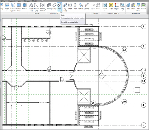
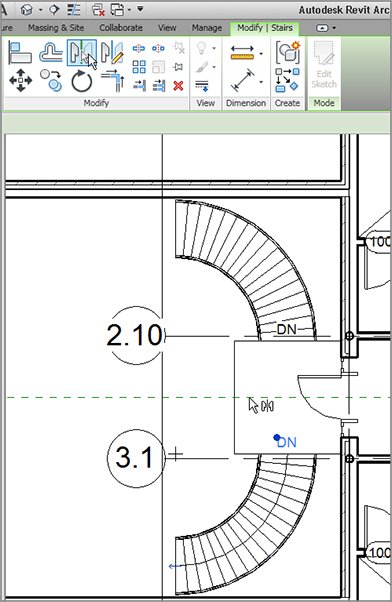
2. Zoom in on the radial entry in the east wing, as shown in Figure 10.1.
3. On the Circulation panel of the Home tab, click the Stairs button, as shown in Figure 10.1.
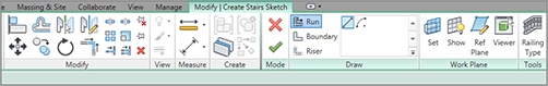
4. You will now be put into the Sketch Mode for the stairs you are about to design, as shown in Figure 10.2.
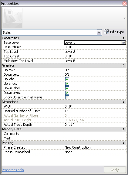
5. In the Properties dialog box, change Base Level to Level 1.
6. Change Top Level to Level 2.
7. Change Multistory Top Level to Level 5 (see Figure 10.3).
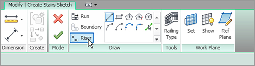
8. On the Draw panel of the Modify | Create Stairs Sketch tab, be sure that Run is selected.
FIGURE 10.1 Click the Stairs button on the Circulation panel of the Home tab.
FIGURE 10.2 The Modify | Create Stairs Sketch Mode
FIGURE 10.3 Changing the Element Properties of the stairs
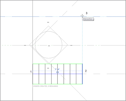
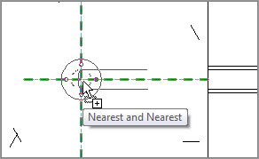
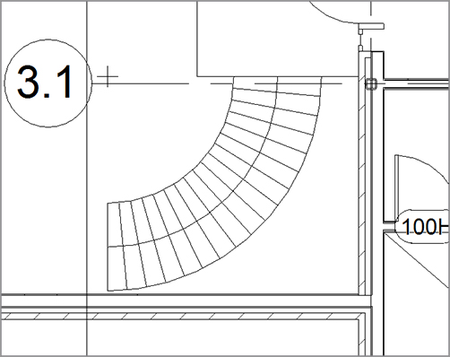
9. Pick the intersection of the floor edge and grid 3.1 for the first point of the stairs. This spot is labeled 1 in Figure 10.4.
10. Move your cursor to the right. You will be able to see a faint display indicating that you have a certain number of risers created and a certain number remaining.
11. When you see that nine risers have been created, with nine risers remaining, pick the spot labeled 2 in Figure 10.4.
12. Move your cursor straight up (north) until you get to the grid intersection labeled 3 in Figure 10.4. When you see this, pick the third point.
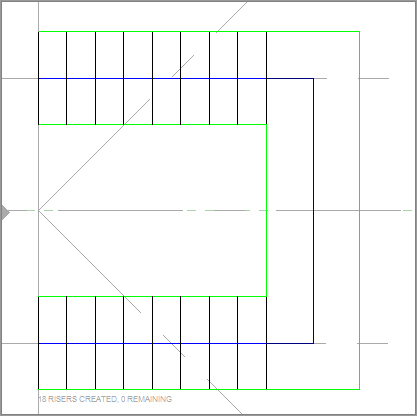
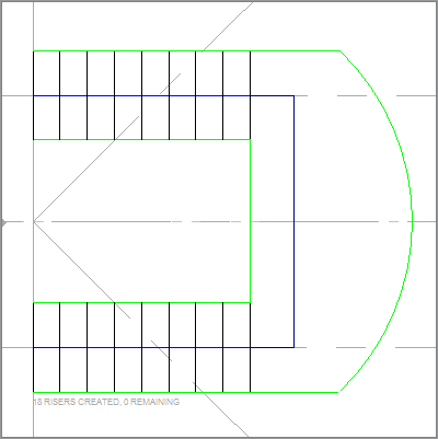
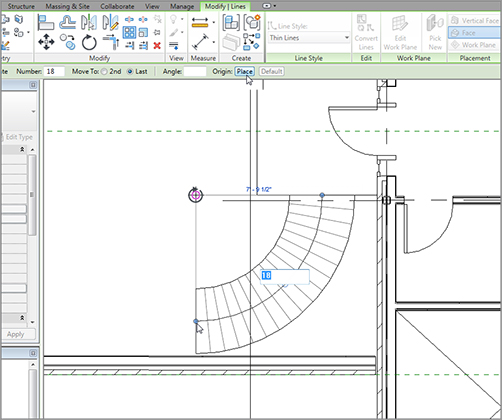
13. Move your cursor to the left, all the way past the floor landing. Revit reports that you have 18 created, 0 remaining (see Figure 10.5).
14. When you see the second flight completed, pick the last point. Revit draws both flights as well as the landing (see Figure 10.6).
With the basic layout completed, it is time to take a look at the perimeter of the stairs. If you are looking for any architectural design outside of the basic box that you get when you place a staircase, you’ll want to edit the boundary.
Modifying Boundaries
With the main stairs in place and laid out, you can now start modifying the profile. Given that this is a five-tiered, multilevel staircase, the boundary will be somewhat limited, but not to the point where you can’t make something pop out of your design.
To modify the boundary, follow along:
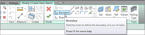
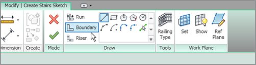
1. On the Modify | Create Stairs Sketch tab, click the Boundary button, as shown in Figure 10.7.
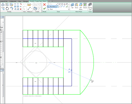
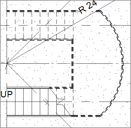
2. On the Draw panel, click the Start-End-Radius Arc button, as shown in Figure 10.8.
3. Draw an arc on the outside of the landing at an 8´–0˝ (2400mm) radius, as shown in Figure 10.8.
FIGURE 10.8 Add a radius to the outside of the landing.
With the radius drawn in, it is important to pause at this point. What you have here is an extra line. Similar to sketching a floor, if you have any overlapping line segments or gaps, Revit will not let you continue. Also, if you have any extra lines, Revit will not let you continue.
Let’s clean up the stairs:
1. Click Modify or press the Esc key twice and then select the straight green line at the outside of the landing.
2. Press the Delete key on your keyboard. The line is removed.
With the boundary in place, it is time to select the railing system you are going to use. Out of the box, Revit provides only four choices. You will select one of those choices for this staircase, but you will add to the list later in this chapter.
Revit provides only four railing systems as a default. You can choose one of these four railings to apply to the staircase during the Sketch Mode of the stairs.
Follow this procedure to apply a railing to the stairs:
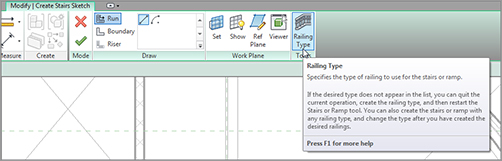
1. On the Modify | Create Stairs Sketch tab, click the Railing Type button, as shown in Figure 10.10.
Normally, when you are dealing with a large, multistory staircase, you should check it out in 3D to make sure all went off as planned. This case is no exception!
1. Click the Default 3D View button on the Quick Access toolbar.
2. In the 3D view, zoom in on the radial entry.
3. Select the radial wall and right-click.
4. From the context menu, choose Hide In View Elements.
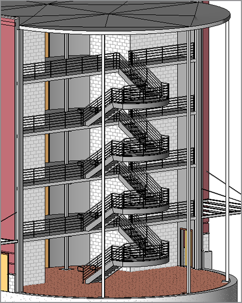
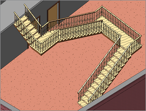
You should now examine your stairs (see Figure 10.13).
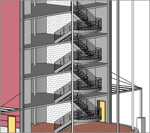
FIGURE 10.13 The stairs in 3D with the radial entry “peeled back”
Here’s a problem: the railing just stops dead at the stringer. This may have been acceptable practice around the time, say, when the wheel was still on the drawing boards. We need some kind of ADA (Americans with Disabilities Act) compliance here at the bottom of the stairs. To accomplish this, follow along with the next procedure.
To begin, go to the book’s web page at www.sybex.com/go/revit2012ner. From there you can browse to Chapter 10 and find the file called ADA-Pipe.rfa. You can then download it to your computer. Now perform the following steps:
1. On the Insert tab, click the Load Family button.
2. Browse to the directory where you stashed the family you just downloaded, and load ADA-Pipe.rfa into your model.
3. Go to the Level 1 floor plan.
4. Zoom in on the bottom of the stairs.
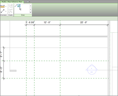
5. On the Work Plane panel of the Home tab, click the Reference Plane button.
6. On the Place Reference Plane tab, click the Pick Lines button, as shown in Figure 10.14.
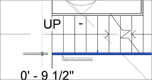
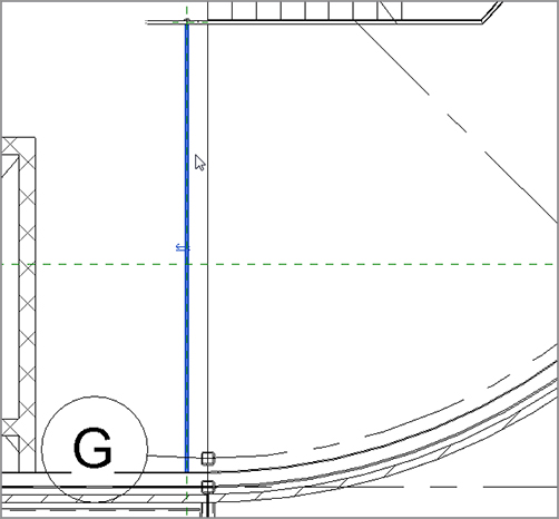
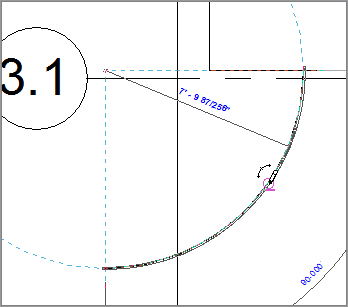
7. Offset a reference plane 9 1/2˝ (237mm) to the left of the bottom riser, as shown in Figure 10.14.
8. Draw another reference plane from the center line of the bottom railing to the left about 2´–0˝ (600mm), as shown in Figure 10.14.
9. On the Home tab, click the Place A Component button.
10. In the Properties dialog box, select ADA – Pipe.
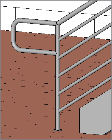
11. Press the spacebar once to rotate the family into place, so it is oriented as shown in Figure 10.15.
12. Place the family at the intersection of the two reference planes, as shown in Figure 10.15, and then press Esc twice or click Modify.
FIGURE 10.14 Add two reference planes as indicated here.
FIGURE 10.15 Placing the family in the intersection
Extending the Railings
You have just added a family to finish off the stairs at the bottom. The next step is to extend the railings on the stairs to meet the new family. There is one obstacle, though: the railing on the stairs already has an ending post. The trick is to remove the default ending post, and replace it with the custom ADA post you just loaded into your model.
The objective of the next procedure is to extend the railings on the stairs to the ADA posts you just added to the model:
1. In the plan, select the bottom railing, as shown in Figure 10.16. Make sure you are not selecting the stairs.
FIGURE 10.16 Selecting the railing, not the stairs
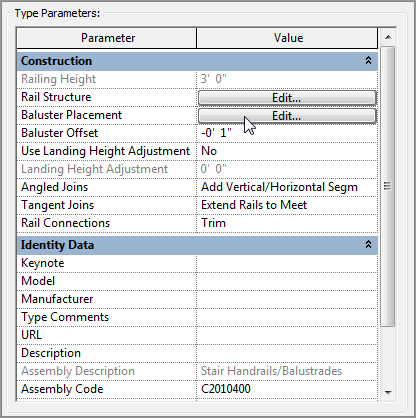
2. In the Properties dialog box, click the Edit Type button.
3. Click Duplicate.
4. Call the new railing Entry Stair Railing.
5. Click OK.
6. In the Baluster Placement row, click the Edit button, as shown in Figure 10.17.
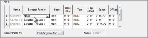
At the bottom of the Edit Baluster Placement dialog box, you’ll see a Posts category. Within the Posts category is a chance to place a post at the start, end, or corner of the railing:
1. For the Start setting, select None from the list, as shown in Figure 10.18.
FIGURE 10.17 Click Edit next to Baluster Placement
FIGURE 10.18 Setting the start of the railing to None removes the post that Revit provides only at this end of the railing.
2. Click OK twice.
3. Select the railing on the inside of the stairs.
4. In the Type Selector, change the type to Entry Stair Railing.
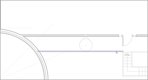
It’s time to stretch the railing on the stairs to meet up with the family. This procedure is best done in plan view, where you can see exactly how far you need to stretch the railing:
1. Select the bottom (south) railing.
2. On the Modify | Railings tab, click the Edit Path button.
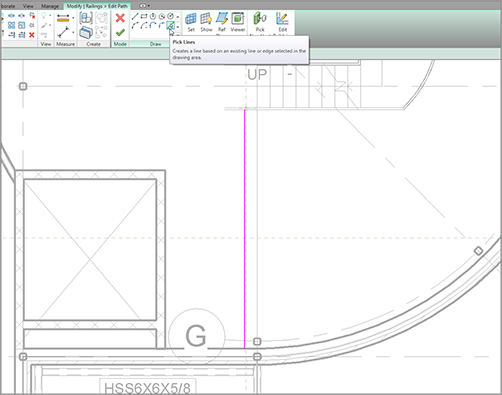
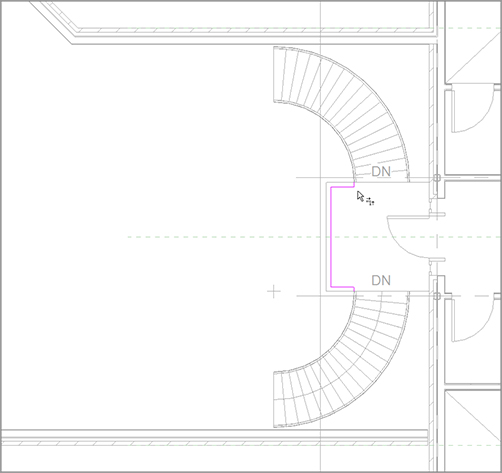
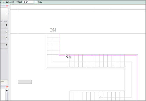
3. Click the Align button on the Modify | Railings Edit Path tab, as shown near the top left of Figure 10.19.
4. For the first alignment, pick the back edge of the family you loaded, as shown in Figure 10.19.
5. Now, pick the magenta railing line. (When you hover over the magenta line, you will see an endpoint icon. When you do, click it.)
The magenta line will extend to the family (see Figure 10.19).
FIGURE 10.19 Aligning the end of the railing to the new family
6. Click Finish Edit Mode.
7. Go to a 3D view to make sure the railings align (see Figure 10.20).
FIGURE 10.20 Check out the railing in 3D to ensure proper alignment.
It would be nice if this were the only place that this railing extension needed to go. The rest of the procedure will step you through the process of adding this extension to the inside railing and then copying it up to the other levels:
1. Copy the ADA – Pipe family up to the inside railing. Make sure you go straight up, as shown in Figure 10.21.
2. Select the inside railing.
3. On the Modify | Railings tab, click the Edit Path button.
4. Click the Align button.
5. Align the magenta line with the ADA – Pipe family, as shown in Figure 10.21.
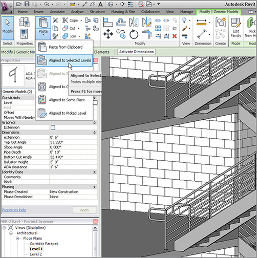
6. Press Esc twice and then select both families.
7. On the Modify | Generic Models tab, click the Copy To Clipboard button on the Clipboard panel (it is the third panel from the left).
8. Choose Paste Aligned To Selected Levels, as shown near the top left of Figure 10.22.
9. Pick Levels 2, 3, and 4, and then click OK. Does your staircase look like Figure 10.22?
FIGURE 10.21 Copying and aligning the inner railing to the ADA family
It’s getting close, but it seems as though there is nothing keeping people from falling off the second, third, fourth, and fifth levels! I don’t know about you, but I think this is the perfect place to put a separate railing and tie it into the existing stair railing.
Railings, of course, can be drawn independently from a stair. Tying the railing into the stair, however, requires a little more patience. That being said, it becomes obvious that Revit reflects the real world when it comes to railings. If you have a railing that is difficult to build, it will probably be difficult to model. Also, if you arrive at an intersection that cannot be physically accomplished in the field, then guess what? You will struggle trying to get it into Revit.
To add some railings at the landings and tie them into the stair railings, follow these steps:
1. In the Project Browser, go to the Level 2 floor plan.
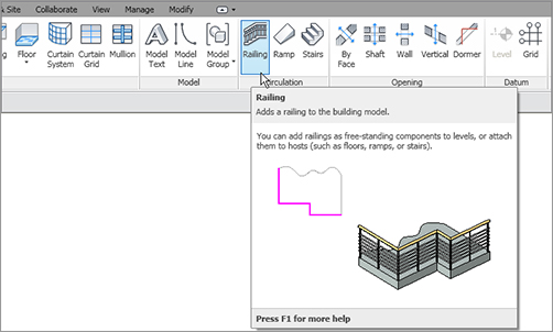
2. On the Home tab, click the Railing button, as shown in Figure 10.23.
FIGURE 10.23 Click the Railing button on the Circulation panel of the Home tab.
3. Make sure that Type is set to Handrail Pipe.
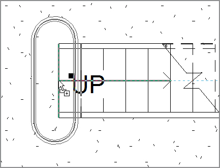
4. On the Draw panel, make sure the Pick Lines icon is selected.
5. Change the Offset to 10 1/2˝ (262mm) on the Options bar.
6. Pick the front edge of the floor, as shown in Figure 10.24. The sketch line should now be set back from the edge of the landing with a 10 1/2˝ (262mm) clearance.
7. The magenta line is going to be way too long. Select it and drag the grip down to the point shown in Figure 10.24.
8. At the bottom of the railing, select the grip and drag it out of the wall as well. When you are finished, click the Finish Edit Mode button (see Figure 10.24).
9. In the Properties dialog box, click the Edit Type button.
13. In the Baluster Placement row, click the Edit button.
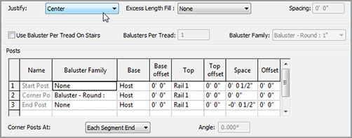
14. In the Posts field, change the Start and End Post to None (as shown in Figure 10.25).
15. Also, just above the Posts field, change the Justify option to Center (again, see Figure 10.25).
16. Click OK twice.
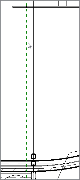
Your railing needs to be centered on the reference plane. It may or may not be. If it is not, select the railing. You will see a blue flip grip (double-arrow grip) in the middle of the railing. Pick it, and your railing will flip (see Figure 10.26).
FIGURE 10.25 Configuring the railing for the landing
FIGURE 10.26 The railing centered on the reference plane
The next step is to create a railing between the two stair sections. This process can be a tad tricky, but once you get the progression, you will see why it needs to be done in the following manner:
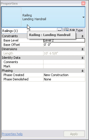
1. On the Home tab, click the Railing button.
2. In the Properties dialog box, make sure Type is set to Landing Handrail, and click OK.
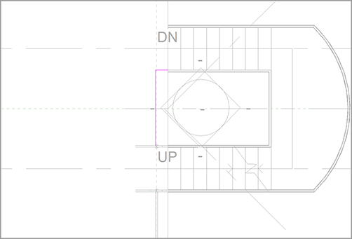
3. Using the same 10 1/2˝ (262mm) offset, draw the sketch of the railing as shown in Figure 10.27.
FIGURE 10.27 Adding the railing to the middle of the stair landing
Now that the two railings are in place, you can use basic editing commands to create an occurrence of the railing on the other side of the stairs. You can either mirror the railing on your own, or if you wish, you can follow along with these steps:
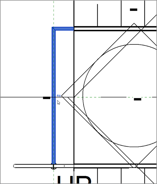
1. Select the south railing, as shown in Figure 10.29.
2. Click the Mirror – Pick Axis button on the Modify | Railings tab.
3. For the reference, pick the center reference plane.
4. Make sure the railing is abutting the north wall.
5. Select the north railing, as shown in Figure 10.30.
6. On the Modify | Railings tab, click the Edit Path button.
7. Draw a connecting piece, as shown in Figure 10.30.
8. After the railing is sketched in, click the Finish Edit Mode button on the Mode panel to the right.
FIGURE 10.29 Mirroring the railing to the north side of the stairs
FIGURE 10.30 Adding the connecting piece to the railing
At this point, it is a good idea to check out your railing in 3D because you are about to copy it to the levels above.
It’s copy time! The next objective is to copy these three railings up to the next three levels. You can proceed on your own and use Copy/Paste Aligned, or you can follow along with this procedure:
1. In the Project Browser, go to the Level 2 floor plan.
2. Select the three railings you added to Level 2. Because you just created this railing type, you can select one and use the right-click menu option Select All Instances to save time.
3. On the Modify | Railings tab, click the Copy To Clipboard button on the Clipboard panel.
4. Click Paste Aligned To Selected Levels.
5. Select Levels 3, 4, and 5, and then click OK.
6. In the Project Browser, go to the Level 5 floor plan.
7. Delete the bottom (south) railing.
8. Select the smaller, middle railing, as shown in Figure 10.31.
9. On the Modify | Railings tab, click the Edit Path button.
10. Extend the line down to the south wall, as shown in Figure 10.31.
Phew! You have built a set of stairs. The good thing is that it’s one sweet staircase. The bad thing is that you used all the default layouts and materials. It’s time to get into some more complicated shapes and styles.
Before you get started here, you should know that you will create this staircase by using the separate stair components. You can try to make a winding staircase by using the Run function, similar to the one you used earlier, but in many cases (especially when you run into an existing staircase in either a renovation project or an addition), you may just need to draft the stairs and then model over the top of the drafting lines. What? Drafting in Revit? Of course. How else can you expect to get anything done?
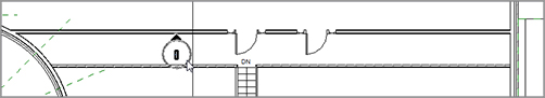
The first thing you will need to do is make modifications to the floor in a specific area to create a landing, as follows:
1. In the Project Browser, go to the Level 2 floor plan.
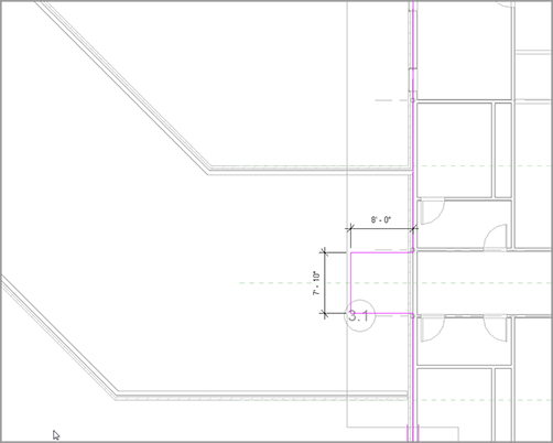
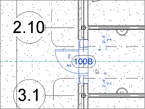
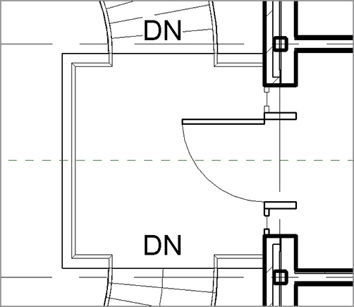
2. Zoom in on the area between the corridor and the east wing, as shown in Figure 10.33.
3. Select the Level 2 floor in the east wing.
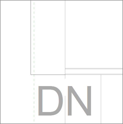
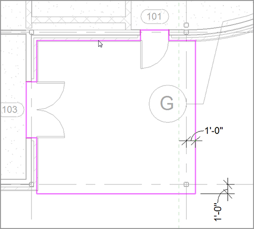
FIGURE 10.33 Creating a landing. You will add a door in a moment.
4. After the floor is selected, click the Edit Boundary button on the Mode panel of the Modify | Floors tab.
5. Sketch a landing that is 8´–0˝ (2400mm) long × 7´–10˝ (2350mm) wide, as shown in Figure 10.33. Center it on the reference plane.
6. After the landing is added in, click Finish Edit Mode on the Mode panel. If you are asked to attach the walls to the bottom of the floor, click Yes.
With the landing in place, you can now copy a door up to this level. To do this, you will go to the first floor and copy the door that resides there. You can do this on your own, or you can follow along with the procedure:
1. In the Project Browser, go to the Level 1 floor plan.
3. Copy the door to the Clipboard (click Copy To Clipboard on the Clipboard panel).
FIGURE 10.34 Copying the first-floor door to the Clipboard and pasting it to Level 2
4. Choose Paste Aligned To Selected Levels.
5. Select Level 2 and click OK.
6. In the Project Browser, go back to Level 2. The door and the landing are now in place.
With the landing and the door in place, you can now create a winding set of stairs. The first task is to simply lay out the shape in the plan, using simple drafting lines. The second step is to model over the lines you added by using various stair tools, as follows:
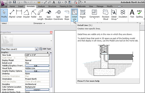
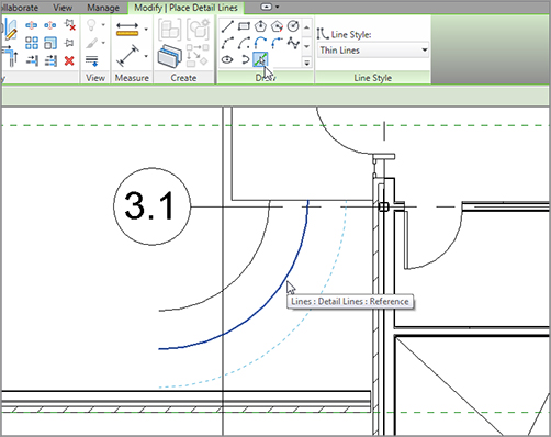
1. Select the Annotate tab.
2. Click the Detail Line button, as shown in Figure 10.35.
FIGURE 10.35 Click the Detail Line button on the Annotate tab.
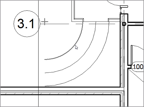
3. On the Draw panel, click the Start – End – Radius – Arc button, as shown near the top of Figure 10.36.
4. For the first point of the arc, pick the midpoint of the landing, as shown in Figure 10.36.
5. Move your cursor down and at 135 degrees from the first point picked.
6. Extend your cursor 11´–0˝ (3300mm), as shown in Figure 10.36, and then click to set the second point.
FIGURE 10.36 With the Start – End – Radius – Arc, first start at the midpoint of the landing, and then go southwest at an angle of 135 degrees and a distance of 11´–0˝ (3300mm).
7. To form the arc, move your cursor to the right until the radius snaps into place. When it does, pick the point, as shown in Figure 10.37.
8. Press Esc.
9. On the Draw panel, click the Pick Lines icon.
FIGURE 10.37 Picking the third point to form the arc. It will be tangent upon the first two points you picked.
10. On the Options bar, add an increment of 2´–0˝ (600mm) to the Offset field (see Figure 10.38).
11. Offset the center arc to the right, and then to the left, forming a 4´–0˝ (1200mm) overall winder, as shown in Figure 10.38.
12. Press Esc.
13. Click the Line tool, make sure Offset is set to 0, and then draw a straight line at each end of the arcs, as shown in Figure 10.39.
FIGURE 10.38 Adding two more arcs based on the centerline of the first
FIGURE 10.39 Adding two straight lines at each end of the arcs
Okay, take a breather. Compare the examples in the book to what you have. Are you close? If not, go back and investigate.
The next step is to make an array of the straight lines you just added. These lines will wind up being your guidelines for your risers.
1. Press Esc, and then select the smaller arc, as shown in Figure 10.40.
It’s time to start modeling the stairs. This procedure is nothing more than tracing the lines you have already added to the model. To do this, you are going to utilize the tools available that you have not touched in the previous staircase, as follows:
1. On the Home tab, click the Stairs button.
2. In the Properties dialog box, change Base Level to Level 1.
3. Change Top Level to Level 2.
4. Click Edit Type.
5. Click Duplicate.
6. Call the stairs Corridor Entry Stairs.
7. Click OK.
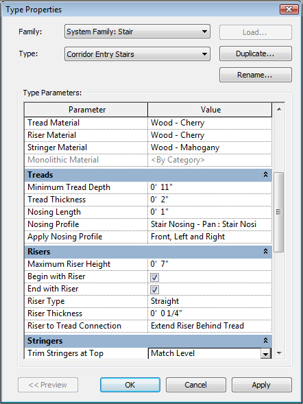
8. For Tread Material, click in the field that reads <By Category>.
9. You will see a […] button. Click it.
10. Choose Wood – Cherry for the Tread Material. Click OK.
11. For Riser Material, do the same.
12. For Stringer Material, select Wood – Mahogany (see Figure 10.43).
13. Under the Treads category, select Front, Left, and Right for Apply Nosing Profile.
14. In the Stringers category, select Match Level for Trim Stringers At Top (see Figure 10.43).
15. Change the Right and Left Stringers to Open.
16. Click OK to get back to the model.
It’s now time to add the stairs to the model. To do this, you will first sketch the boundary:
1. On the Modify | Create Stairs Sketch tab, click the Boundary button, as shown in Figure 10.44.
6. Pick all of the lines you arrayed. This includes the bottom and the top lines (see Figure 10.46).
7. Click Finish Edit Mode on the Mode panel.
FIGURE 10.46 Picking the detail lines to lay over the stair components
With the stairs roughed in, you need to get a better look at them. If you use the default 3D view, you need to turn off way too many items to see your stairs. Let’s add a perspective view just to see what’s going on here!
If you are confident in adding your own perspective view, go ahead and put one in, and name it East Entry from Corridor. If not, follow along with the procedure:
1. In the Project Browser, go to the Level 1 floor plan.
2. On the View tab, click the 3D View Camera button.
Now that you have a perspective on your stairs, you can see multiple issues with the railing. The first, more prominent issue is that the railings seem to be floating. This occurs when the stringers are switched from closed to open. Revit still thinks there is a stringer underneath the railings. You will need to move the railings in 2˝ (50mm) to fix this problem.
Making Railing Adjustments
Yes, you have been making railing adjustments this entire chapter. Get used to constantly having to do this for each unique situation. This staircase requires us to add some posts back into the railing so it can stop and end at the stringer. But first let’s move the railing back onto the actual treads:
1. Go to the Level 2 floor plan.
2. Select the top railing, as shown in Figure 10.48.
3. On the Modify | Railings tab, click Edit Path.
4. Click the Offset button on the Modify panel, as shown in Figure 10.48.
5. In the Offset field in the Options bar, type 2˝ (50mm).
6. Deselect the Copy option.
7. Offset the railing into the stairs 2˝ (50mm), as shown in Figure 10.48.
The next series of steps involves mirroring the stairs to the other side of the landing. Then, of course, you need to add a landing railing so people don’t just walk out the door and off the ledge.
1. Go to the Level 2 floor plan in the Project Browser.
2. Select the stairs and the railings.
3. On the Modify | Multi-Select tab, click the Mirror Pick Mirror Axis button, as shown in Figure 10.50.
4. Pick the center reference plane (I told you this thing would come in handy).
Your stairs are now mirrored to the other side of the landing, as shown in Figure 10.50.
It’s time to tie in the railings. If you are feeling up to the challenge, try it on your own by using the landing railing you used in the front entry stairs. If not, just follow along with these steps:
1. On the Home tab, click the Railing button.
2. In the Type Selector, change the type to Landing Handrail (if it is not already selected), as shown in Figure 10.51.
9. Trim the corners so your railings look like Figure 10.53.
10. On the Mode panel, click Finish Edit Mode.
11. You may have to flip the railing by selecting it and then clicking the Flip arrow. Your railing should look like Figure 10.54.
12. Add two more railings between the stairs and the brick wall. Your stairs should look like Figure 10.55.
Great! You are getting there. Now it is time to see how a staircase and the accompanying railings come together. For example, it sure would be nice to have a railing with spindles, or better yet, panels added to them. Also, a nice half-round bull nose would improve your staircase. The next section focuses on this concept.
FIGURE 10.53 Connecting the landing railing to the stair railing
FIGURE 10.54 The railing at the front of the landing
Similar to the model as a whole, stairs and railings compose separate families that come together to form the overall unit. Although stairs and railings are considered a system family (a family that resides only in the model), they still heavily rely on hosted families to create the entire element.
The next procedure involves loading separate families into the model, and then utilizing them in a new set of stairs and railings you will create in the west wing:
1. In the Project Browser, go to the Level 3 floor plan and change the Detail Level to Fine.
2. Zoom in on the west wing.
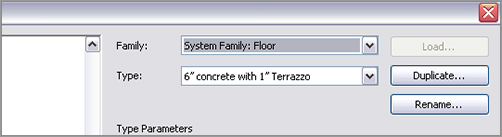
3. On the Home tab, click the Floor button.
4. Select the 6˝ concrete with 1˝ Terrazzo floor system from the Type Selector, as shown in Figure 10.56.
5. On the Draw panel, verify that Pick Walls is selected.
FIGURE 10.56 You must add a floor at the Level 3 floor plan for the stairs to have a landing.
6. Pick the walls, and make sure the lines are set to the core centerline, as shown in Figure 10.57.
7. When picking the south wall, set the offset to 5´– 0˝ (1500mm) in the Options bar in Figure 10.57.
FIGURE 10.57 Adding the floor outline to the walls. Be sure to offset the line 5´–0˝ (1500mm) from the south wall. This will be the stair landing.
8. After the sketch lines are in place, click Finish Edit Mode on the Mode panel.
9. Revit asks whether you want to attach the walls that go up to this floor’s bottom. Click No.
10. Next, Revit asks whether you want to cut the overlapping volume out of the walls. Click Yes.
Your floor is now in place. The next item you will tackle is creating a completely custom railing system.
It’s now time to load the components that will make up your stairs. Although Revit makes an attempt to supply you with some families, you will be downloading the families included with this book by going to the book’s web page at www.sybex.com/go/revit2012ner. From there you can browse to Chapter 10 and find the following files:
6210 (2-5_8).rfa
landing.rfa
post.rfa
raised panels.rfa
spindle.rfa
stair nosing.rfa
To get started, you need to load the families into your model so they are available when it comes time to assemble your new railing. If you remember how to do this, go ahead and load all the families that you just downloaded from the web page. If you need some assistance, follow along with the procedure:
1. On the Insert tab, click Load Family.
2. Find the files that you downloaded from the web page.
3. Select all of the files and click Open to load them.
4. Save the model.
The next step is to create a new railing and add some of these items to it:
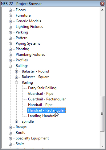
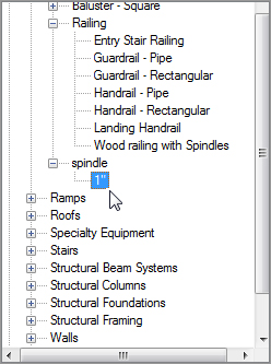
1. In the Project Browser, find the Families category and expand it, as shown in Figure 10.58.
2. Find the Railings category and expand it.
3. Find Handrail – Rectangular and double-click it (see Figure 10.58) to open its Type Properties.
FIGURE 10.58 The railing family called Handrail – Rectangular
4. Click Duplicate.
5. Call the new railing Wood Railing with Spindles.
6. Click OK.
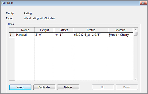
7. In the Rail Structure row, click the Edit button.
8. In the Rails chart, change Name to Handrail, as shown in Figure 10.59.
FIGURE 10.59 Changing the rail. Note that you can add as many rails as you wish. In this case, you are adding only one.
9. Change the profile to 6210 (2-5_8):2 5/8˝.
10. Change Material to Wood – Cherry by clicking the […] button and browsing for the material (see Figure 10.59).
11. Click OK.
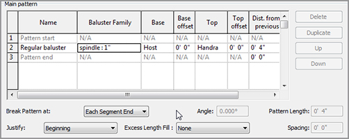
12. Click the Edit button in the Baluster Placement row.
13. In the Main Pattern area, change Baluster Family to spindle 1˝ (see Figure 10.60).
FIGURE 10.60 Adding the spindle to the Main Pattern
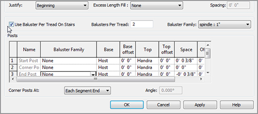
14. Just below the Main Pattern area is the Use Baluster Per Tread On Stairs option. Click it, as shown in Figure 10.61.
15. To the right, you will see the Balusters Per Tread field. Specify two balusters per tread (see Figure 10.61).
16. Change the Baluster Family to spindle 1˝, as shown in Figure 10.61.
17. In the bottommost field is the Posts category. Change each of the three posts to None. Your spindles are all you need (see Figure 10.61).
18. Click OK twice.
FIGURE 10.61 Specifying two balusters per tread and no actual posts
You may or may not have noticed that you did not get the opportunity to change the baluster’s material as you did with the railing. This action must be done in the family itself, as follows:
1. In the Project Browser, you will see a category called Spindle just below Railing, as shown in Figure 10.62. Expand Spindle to expose the 1˝ family.
FIGURE 10.62 Finding the Spindle : 1˝ family to access the material
2. Double-click the 1˝ family to open its Type Properties dialog box.
3. In the Type Properties dialog box, find the Material row and click the […] button. This appears when you click in the field that reads <By Category>.
4. Change Material to Wood – Cherry.
5. Click OK twice.
This completes the railing. After you add it to the stairs, however, there will certainly be some required tweaking. The next step is to customize the stairs themselves.
Because this is the third staircase you have created in the same chapter, you certainly have gained some experience regarding the placement of stairs and railings into the Revit model. You are also becoming familiar with the stair and railings dialog boxes. This last procedure ties all of that together.
Let’s create that staircase:
1. On the Home tab, click the Stairs button.
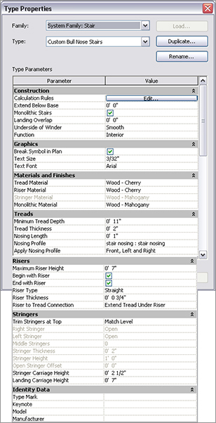
2. In the Properties dialog box, make sure a Stair type is currently in the Type Selector, and click the Edit Type button.
3. Click Duplicate.
4. Call the new staircase Custom Bull Nose Stairs.
5. Click OK.
6. In the Type Parameters, under Construction, turn on the toggle for Monolithic Stairs, as shown in Figure 10.63.
7. Moving down the list, change Monolithic Material to Wood – Mahogany.
8. Change Nosing Profile to Stair Nosing : Stair Nosing (see Figure 10.63).
9. Under the Risers category, change Riser Thickness to 0´–3/4˝ (19mm).
10. For Riser To Tread Connection, choose Extend Tread Under Riser (see Figure 10.63).
11. Click OK.
It is time to configure some of the layout properties. These will enable you to calculate the rise/run count as well as some basic offsets you will need.
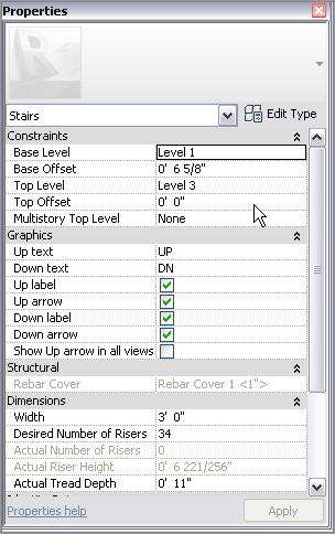
1. In the Properties dialog box, set Base Level to Level 1.
2. Set Base Offset to 6 5/8˝ (165mm), as shown in Figure 10.64.
3. Set Top Level to Level 3. (Yes, this is going to be one long staircase!)
The next step is to place this monster into the model. Although you did not specify a multistory staircase, you will need multiple landings to give your visitors a breather as they travel up the stairs. This layout will require a little more care in the initial planning stage.
1. On the Work Plane panel of the Modify | Create Stairs Sketch tab, click the Ref Plane button.
2. Click the Pick Lines button and then offset a grid, as shown in Figure 10.65. Start with the wall at the right and the new floor edge.
3. On the Modify | Create Stairs Sketch tab, click the Run button.
FIGURE 10.63 Configuring the stairs. As you can see, you have quite a few options.
4. Draw your stairs as shown in Figure 10.66. (Pick the points as the figure is sequenced.)
5. Click the Railing Type button, and change the railing to Wood Railing With Spindles.
6. Click Finish Edit Mode. Your plan should look like Figure 10.67.
FIGURE 10.64 The Base Offset value is set to 6 5/8˝ (165mm).
FIGURE 10.65 Using dimensions to lay out the centerlines of the stairs
FIGURE 10.66 Picking the intersections of the reference planes to determine where the stairs will be going
Remember how the railings seemed to be floating when you opened the stringers in the entry staircase? You are going to have the same issue here. The next procedure is to move the railings in 2˝ (50mm) in the plan so there is adequate bearing on the stairs:
1. In the plan, select the top railing, as shown in Figure 10.68.
2. On the Modify | Railings tab, click Edit Path.
3. On the Edit panel, click the Offset button, as shown in Figure 10.68.
4. On the Options bar, enter 2˝ (50mm) in the Offset field.
5. Deselect Copy.
6. Hover your cursor over one of the magenta sketch lines and press the Tab key. This selects the entire railing line.
7. Make sure the dotted alignment line is facing the inside so the sketch line moves as shown in Figure 10.68. (If it is not, press the spacebar to flip it.)
8. After the railing is offset in, click Finish Edit Mode.
9. Repeat the procedure on the other railing.
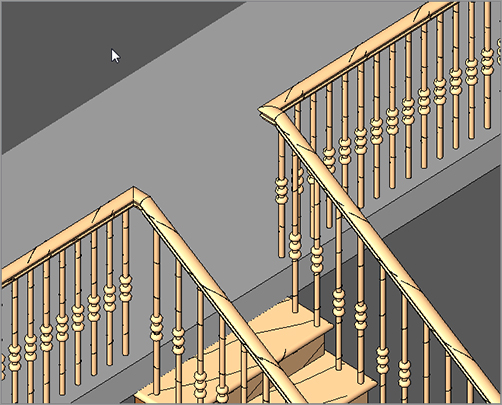
10. Go to (or make) a 3D view to check out the stairs. They should resemble Figure 10.69.
FIGURE 10.68 Offset the railing line down 2˝ (50mm) from the original location.
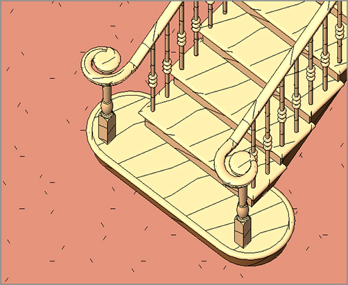
FIGURE 10.69 The stairs as shown in 3D. Notice the nice bull nose and the railings.
The next step (pun intended) is to add a landing to the bottom of the stairs. This requires creating a family. Although this topic is covered in Chapter 17, “Creating Families,” this family has been created, and you have downloaded the families needed to create this step in the stairs.
Adding a Custom Landing
The reason you left the 6 5/8˝ (165mm) offset for the bottom tread is because you need to introduce your own version of how that bottom tread should look. As mentioned earlier, this family has been loaded. If you have not already loaded the family, go to www.sybex.com/go/revit2012ner. From there you can browse to Chapter 10 and find the files called Landing.rfa and Post.rfa. After you have loaded these families, proceed with these steps:
1. In the Project Browser, go to the Level 1 floor plan.
2. On the Home tab, click the Place A Component button.
3. In the Properties dialog box, find and select the family called Landing.
4. As you are inserting the family, press the spacebar to rotate the landing into the correct position.
5. Place the landing under the last tread at the point shown in Figure 10.70.
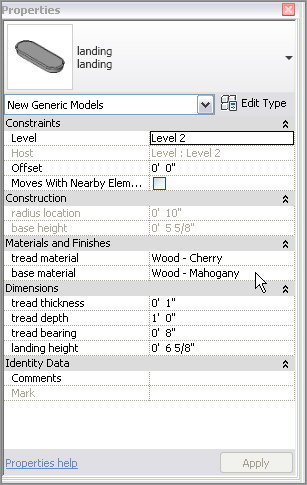
8. In the Properties dialog box, change Tread Material to Wood – Cherry.
9. Change Base Material to Wood – Mahogany and click OK (see Figure 10.71).
The next remaining task is to add a post.
FIGURE 10.71 Changing the landing material to match the theme of the staircase
Adding a Gooseneck
In this style of railing system, it would be nice to have a gooseneck that will catch the railing as it slopes downward and spiral it into the post. Of course, Revit does not have families for this already built, but this book sure does! You should have downloaded the post family earlier in this chapter, but if you did not, go to the book’s website at www.sybex.com/go/revit2012ner. From there you can browse to Chapter 10 and find the file called Post_up.rfa. After you download it and load it into the model, follow these steps:
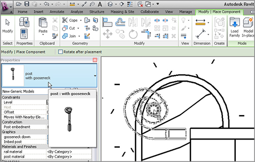
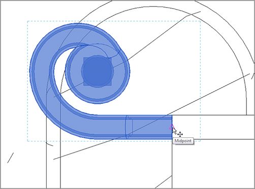
1. In the Project Browser, go to the Level 1 floor plan and zoom in on the landing area, as shown in Figure 10.72.
2. On the Home tab, click the Place A Component button.
3. In the Type Selector, select Post_Up With Gooseneck.
4. As you are placing the post, press the spacebar twice to flip the post into the correct orientation, as shown in Figure 10.72.
5. Place it on the landing slightly away from the stair railing, as shown in Figure 10.72.
6. When the post is placed, select it and change Offset to 6 5/8˝ (165mm) in the Properties dialog box.
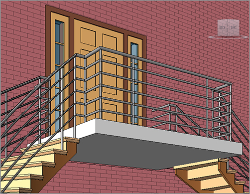
It’s now time to add the railing to the Level 3 balcony. Compared to that landing you just added, this is going to be a snap! If you feel as though you have the experience required to add your own landing railing, go ahead and take a shot. If not, just follow along with the procedure:
1. In the Project Browser, go to Level 3.
2. Zoom in on the stairs.
3. Right-click one of the railings on the stairs and click Create Similar.
4. Sketch a railing that is 4˝ (100mm) in from the face of the landing, as shown in Figure 10.75.
5. Make sure you have a “leg” tied into the stair railing, as shown in Figure 10.75.
6. On the Railing panel, click Finish Edit Mode.
7. Repeat the procedure on the other end (see Figure 10.76).
FIGURE 10.75 Adding the railing. This process is becoming old hat!
The last step is to add a raised-panel stile and rail system along the third-floor wall.
Adding a Raised-Panel Stile and Rail System
The first thing you need to do is to add an entrance to the large Level 3 training room. The corridor will then receive a custom line-based, raised-panel family.
1. In the Project Browser, go to the Level 3 floor plan.
2. On the Home tab, click the Door button.
3. In the Properties dialog box, select Single-Raised Panel With Sidelights : 36˝ × 84˝. On the Options bar, clear Tag On Placement.
4. Place the door in the corridor wall aligned with the stairs, as shown in Figure 10.77.
5. Copy the door 10´–0˝ (3000mm) to the right, as shown in Figure 10.77.
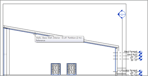
6. On the View tab, click the Elevation button.
7. In the Type Selector, select Interior Elevation.
8. Pick a point, as shown in Figure 10.77; then press Esc.
9. In the Project Browser, right-click on the new elevation and rename it West Wing Balcony Elevation.
10. Open the West Wing Balcony elevation.
11. Stretch the crop region so you can see the entire west wing.
12. On the View Control bar, change Visual Style to Wireframe.
13. On the Home tab’s Work Plane panel, pick Set.
14. In the Work Plane dialog box, make sure Pick A Plane is selected and then click OK.
15. On the Home tab, click the Place A Component button.
FIGURE 10.77 Pick the point as shown for the elevation.
FIGURE 10.78 Picking the far wall to establish a work plane
17. In the Change Element Type menu in the Properties dialog box, select the Raised Panels family.
If you do not have the raised-panel family, you can download it at www.sybex.com/go/revit2012ner. From there you can browse to Chapter 10 and find the file called Raised Panel.rfa. After it is downloaded and loaded in to the model, proceed with the next step.
18. Pick the base point, labeled 1 in Figure 10.79.
19. Pick the second point, labeled 2 in Figure 10.79.
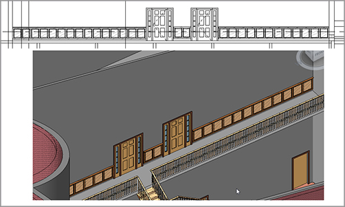
FIGURE 10.79 Adding the line-based, raised-panel family
20. Start the Place A Component command again, and add the raised-panel family between the two doors and to the right. This completes the raised panels for this level.
21. Select all of the raised-panel families on this floor (remember to hold the Ctrl key to add to the selection).
22. In the Material And Finishes category of the Properties dialog box, change the panel material to Wood – Cherry.
23. Change frame material to Wood – Mahogany. See Figure 10.80.
Wow! That was quite a bit on stairs. If you take anything away from this chapter, take away the knowledge that stairs are not going to come easy, but you can create any staircase if you know you will need to create families.
The last section of this chapter focuses on adding ramps to the model. As far as Revit procedures go, ramps are the kid sister to stairs.
FIGURE 10.80 The finished raised-panel, line-based family
When you think of ramps in Revit, think of a one-tread, one-rise staircase at a 1/12 pitch. Ramps are placed in the model exactly in the same way as a stair. You still have the run method, and you can still sketch the ramp by using a boundary.
That being said, let’s start placing a ramp in your model:
1. In the Project Browser, go to the Level 1 floor plan.
2. Zoom in on the radial entry of the east wing at grid intersection F-5 (see Figure 10.81).
3. You need to create a flat landing, so on the Home tab, click the Floor button.
4. Click Edit Type in the Properties dialog box.
5. Select Generic – 12˝ Filled.
6. Click Duplicate.
7. Call the new floor Exterior Concrete Slab.
8. Click OK.
9. Click the Edit button in the Structure row.
10. Change Structure [1] Material to Concrete – Cast-in-Place Concrete.
11. Change Thickness to 6˝ (150mm).
12. Click OK twice to get back to the model.
13. Place the concrete at the points shown in Figure 10.81.
14. When the slab is in place, click the Finish Edit Mode button.
15. Click No in the next dialog box.
Now it is time for the ramp. You will set the ramp’s properties for the top to Level 1, and the bottom is also going to be at Level 1 but with an offset.
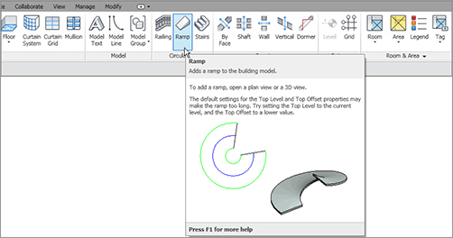
1. On the Home tab, click the Ramp button, as shown in Figure 10.82.
FIGURE 10.82 Click the Ramp button on the Home tab.
2. In the Properties dialog box, click Edit Type.
3. Click Duplicate.
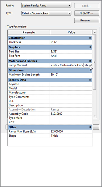
4. Call the new ramp Exterior Concrete Ramp.
5. Click OK.
6. Give it a 6˝ (150mm) thickness.
7. For ramp material, click the […] button and specify Concrete – Cast-In-Place Concrete, as shown in Figure 10.83.
8. Notice that the Maximum Incline Length is set to the ADA standard of 30´–0˝ (10000mm).
9. In the Other category, notice the Ramp Max Slope is set to 1/12.
10. Click OK.
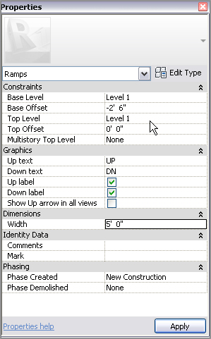
11. In the Properties dialog box, set Base Level to Level 1.
12. Set Base Offset to -2´–6˝ (-750mm), as shown in Figure 10.84.
14. Set Width to 5´–0˝ (1500mm), as shown in Figure 10.84.
15. On the Draw panel, click the Run button.
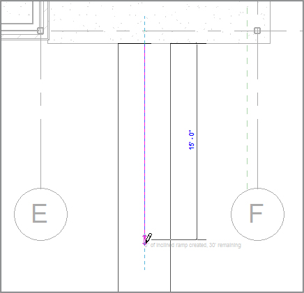
16. In the model, click the first point for the ramp similar to the point shown in Figure 10.85. (You will have to just place the point near the midpoint. Revit does not allow you to snap while in this Sketch Mode for some reason.)
17. Move your cursor down the view (in a southernly direction) 15´–0˝ (4500mm), as shown in Figure 10.85. (You will see the temporary dimension.)
FIGURE 10.85 Pick the first point on the landing and then move your cursor down 15´–0˝ (4500mm).
18. Pick a point about 6´–0˝(1800mm) below the end of the ramp, in alignment with the right boundary, as shown in Figure 10.86. After you pick the second point, the view should read “30´ of inclined ramp created, 0 remaining.”
19. Move your cursor to the right until the ramp stops (see Figure 10.86).
20. On the Modify | Create Ramp Sketch tab, click the Railing Type button.
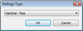
21. Select Handrail – Pipe in the Railings Type dialog box that opens.
22. Click OK.
23. Click Finish Edit Mode.
24. Select the entire ramp (including the railing).
25. Move the ramp so the midpoint of the top of the ramp meets the midpoint of the landing slab.
You may notice immediately that the ramp is sloping in the wrong direction. Also, you need to tie the railings into the slab. If you would like to pick around and see how to do these things on your own, go right ahead. If you would rather go through the procedure, follow along:
1. Select the ramp.
2. Notice a small blue arrow. Pick it—this will flip the direction of the ramp.
3. On the Home tab, click the Railing button.
4. In the Properties dialog box, click Edit Type, change the type to Handrail – Pipe, and click OK.
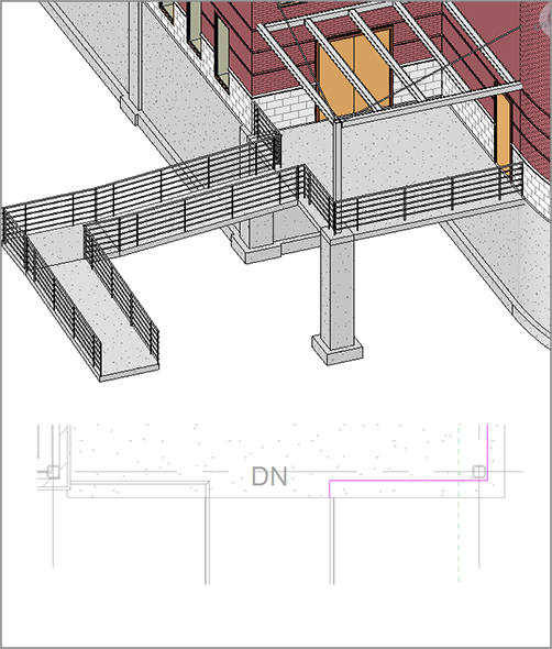
5. Draw a railing in 8˝ (200mm) from the slab edge, as shown in Figure 10.87.
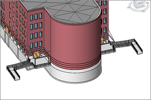
6. Mirror the slab, the ramp, and the railing to the other side of the building, as shown in Figure 10.88.
7. Save the model.
Creating ramps will be a necessary evil in almost every project. Some will be easier than others, and at times they may try your patience. Keep at it, and before long you will have the experience you need to feel confident.
FIGURE 10.87 Adding the railing just as you have been doing this entire chapter