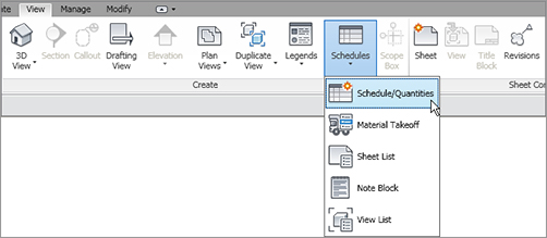
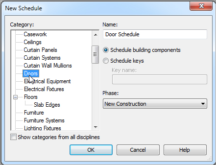
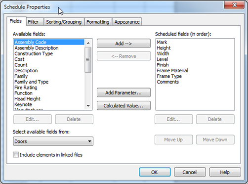
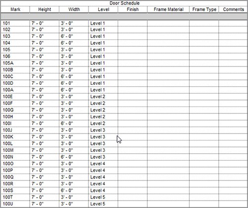
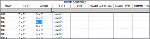
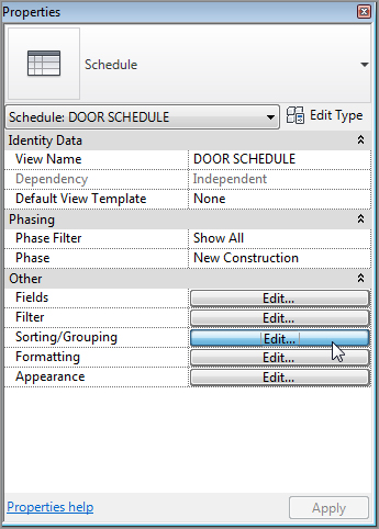
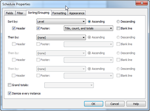
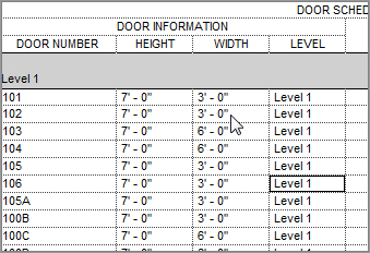
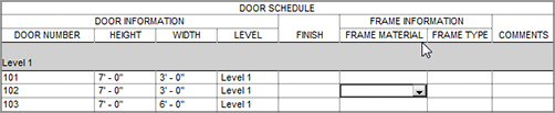
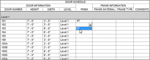
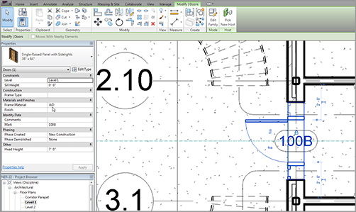
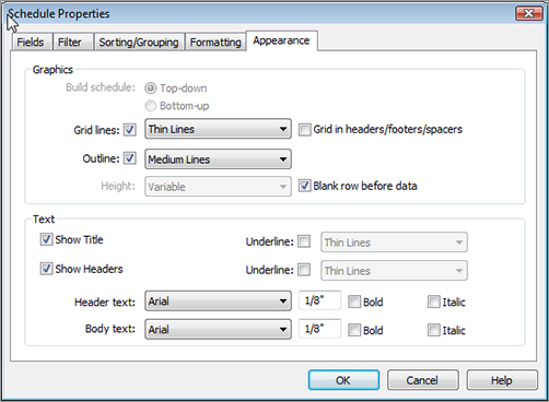
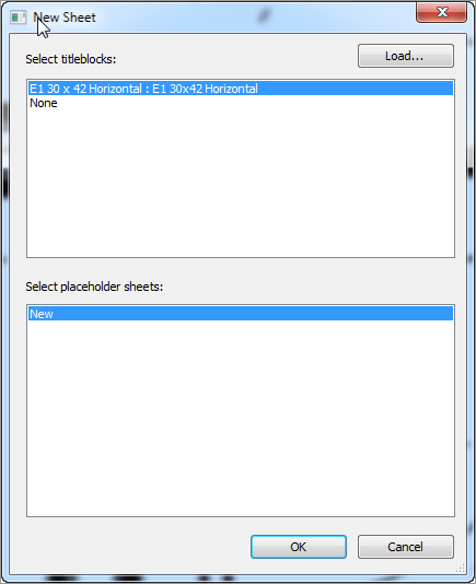
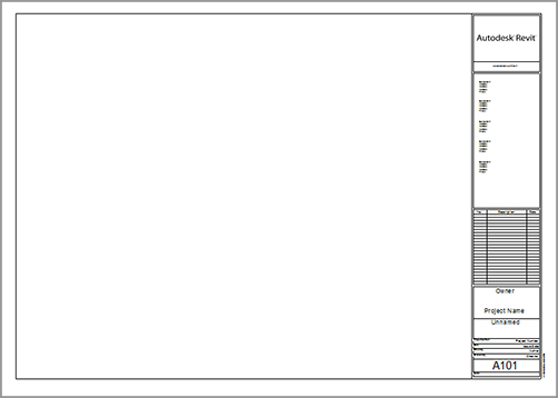
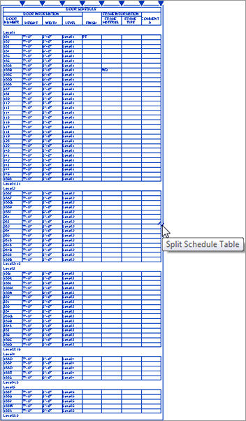
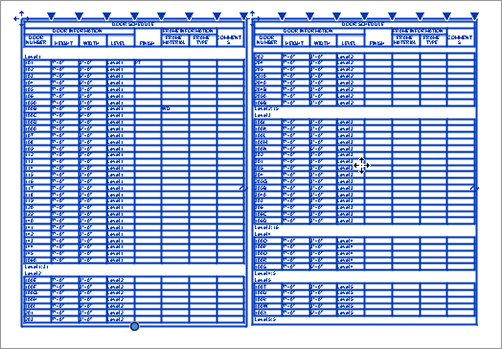
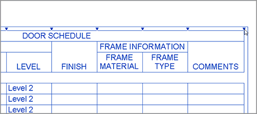
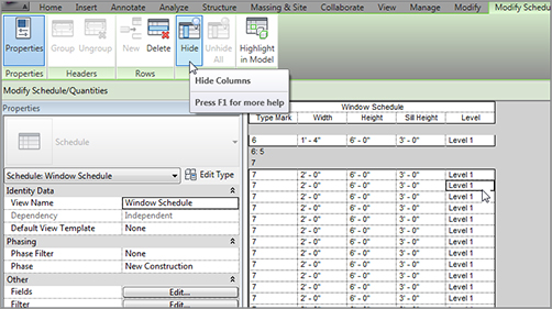
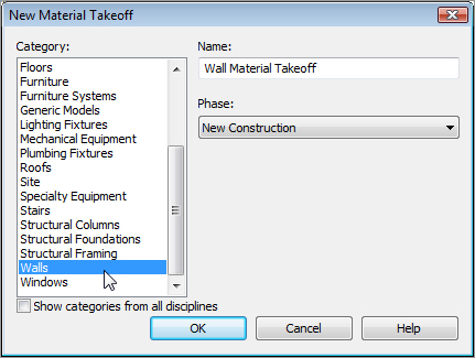
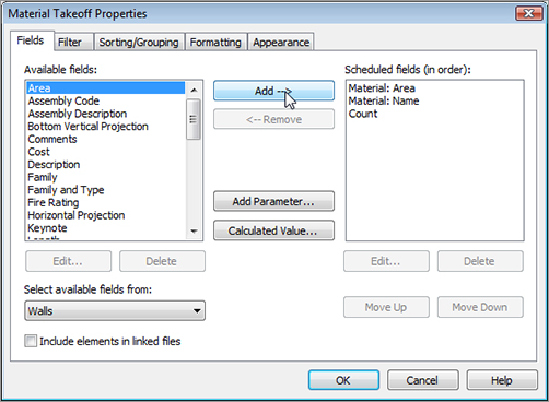
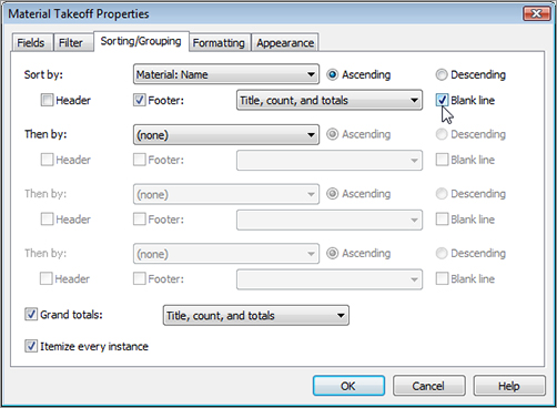
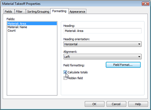
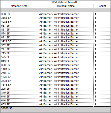
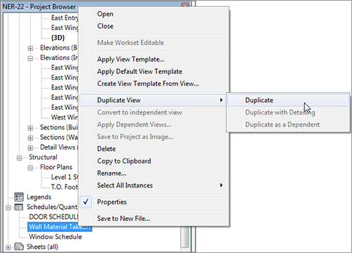
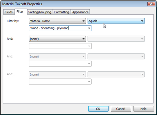
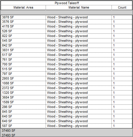
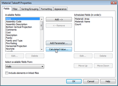
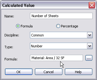
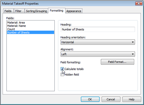
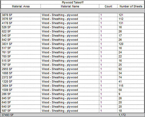
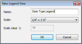
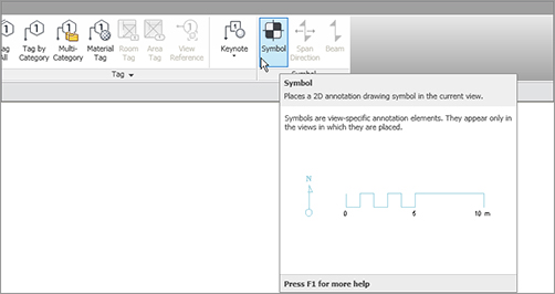
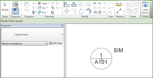
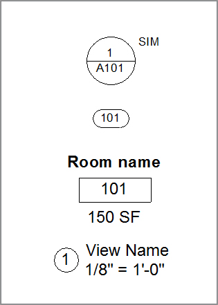
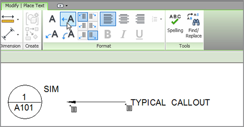
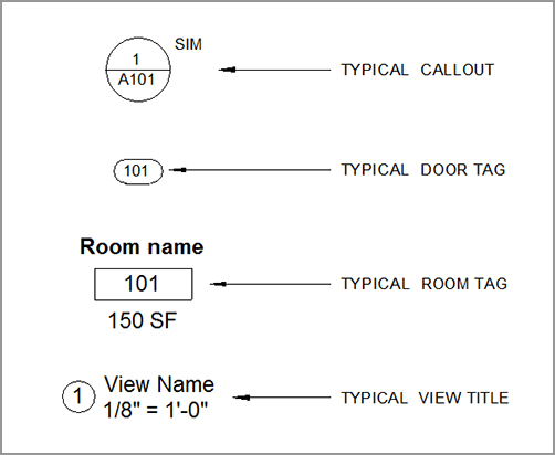
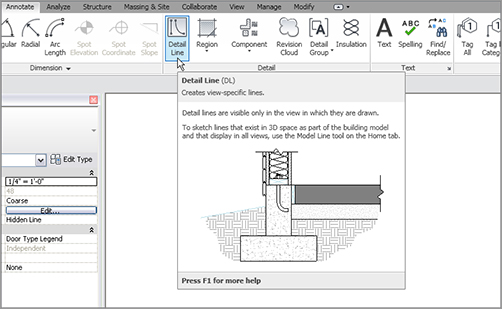
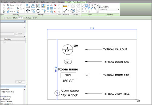
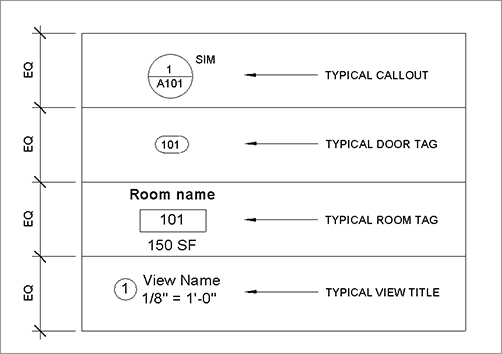
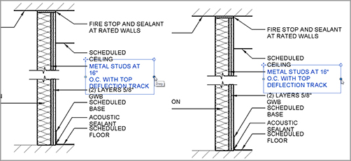
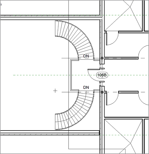
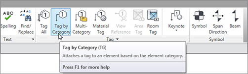
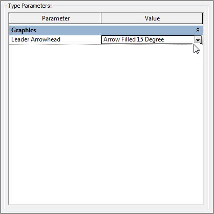
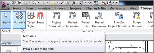
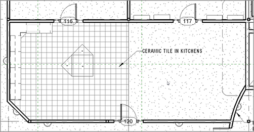
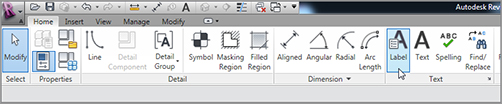
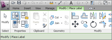
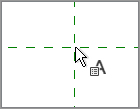
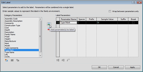
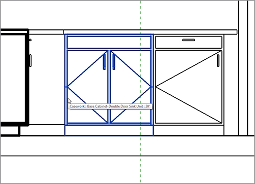
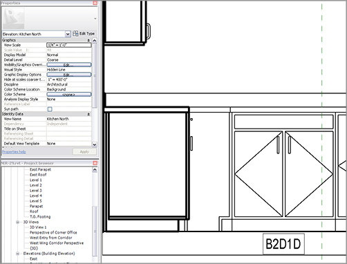
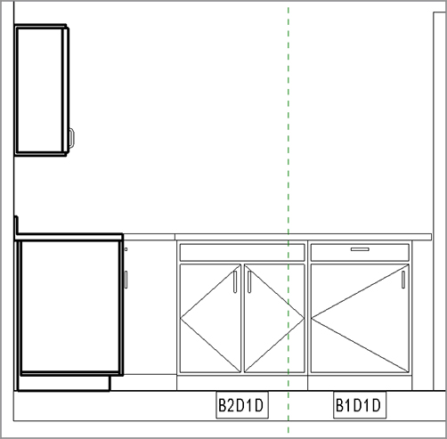
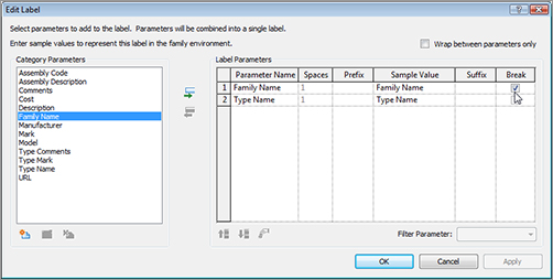
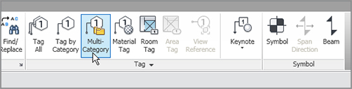
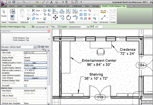
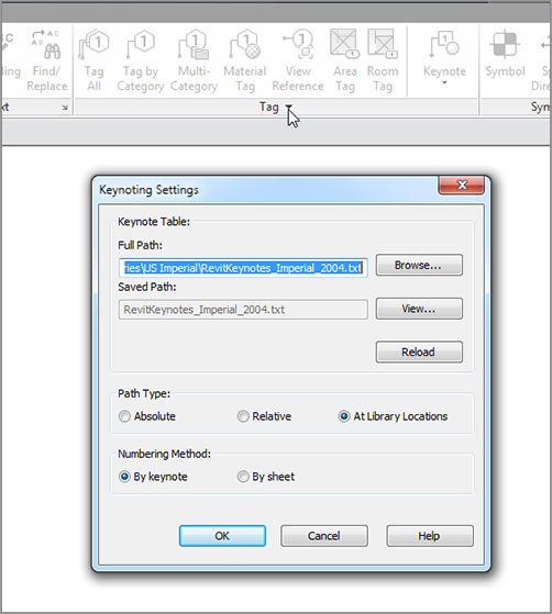
To begin, I want to clarify something specific for the people who have been using AutoCAD Architecture: you don’t need to tag an item in order for it to appear in a schedule in Revit Architecture. You can’t really just draft a schedule either. But this isn’t a bad situation to be in. Say, for example, that you have a typical door schedule. Wouldn’t it be nice to add a door to the model and have that door automatically show up in the schedule? Revit allows you to instantly schedule an item based on a database. A door, for example, already has most of the information you need built into it. Didn’t it seem funny that when you placed a door in the model, it was automatically tagged with a sequential door number? This is the power of BIM. We’re now going beyond 3D. Schedules don’t stop at doors and windows in Revit. You can schedule almost any item that goes into the model. Along with schedules comes the ability to quantify materials and areas. You can even create a schedule for the sole purpose of changing items in the model. In Revit, it’s always a two-way street. The first topic we’ll tackle is creating the most common of the schedules in architecture: the door schedule. When you get this procedure down, you’ll be off and running. The good news is, you have most of the information you need to create a multitude of schedules. The bad news is, the Revit-produced schedules aren’t going to look like your company’s schedules at all. Before we go further, it’s important to note that some of you will be able to get a perfect duplication of your companies’ standard schedules; some of you won’t. Those of you who don’t will have to get as close as possible to your standards and at that point know that sometimes the cost of doing BIM isn’t in the pocket but at the plotter. Given that, let’s get started. I think you’ll find that creating and using schedules is a wonderful experience. You’re about to learn how to save hours upon hours of work, all the while maintaining 100 percent accuracy. To begin, open the file you’ve been following along with. If you didn’t complete the previous chapter, go to the book’s web page at FIGURE 11.1 Click the Schedule/Quantities button on the View tab. FIGURE 11.2 Select Doors, and click OK. FIGURE 11.3 Adding the fields to produce a door schedule FIGURE 11.4 The door schedule up to this point The next step is to start organizing your data in your preferred display format. You have a long way to go, but when you’re finished, you can use this schedule over and over again. Because Revit is a database, let’s think of building a schedule as creating a query in a database, because that’s exactly what you’re doing. By creating a sort, you can start to see your doors in groups and have a tangible understating of where you are. Let’s get started: FIGURE 11.5 Edit all the field names. FIGURE 11.6 Click the Edit button in the Sorting/Grouping row. FIGURE 11.7 Sorting the schedule by level The next step is to group the header information the way you would like it. Most schedules include groups such as Frame Material and Frame Type. You’ll create similar groupings. Although this step isn’t crucial to producing an accurate, readable schedule, it’s important in the attempt to get this Revit-produced schedule to look like the schedule you’ve been using for years in CAD. The objective of this procedure is to combine the header content into smaller groups under their own header, similar to what you can do in a spreadsheet. To begin controlling the schedule headers, follow these steps: At the top of the schedule are the title (DOOR SCHEDULE) and the headers (which include MARK, HEIGHT, WIDTH, and LEVEL, among others), as shown in Figure 11.8. Focus your attention here. FIGURE 11.8 Click and drag across the four cells to activate the Group button. It would be nice if the defaults in Revit were all caps, but they aren’t. The next procedure will rename some of the headers, but it won’t change any values: FIGURE 11.9 Adding the new header and changing the descriptions FIGURE 11.10 The groups are complete. Now it’s time to begin filling out some of the blank fields. This is where you can increase productivity by using schedules. Instead of going door by door in the model, you have a list of every door right in front of you! In Revit, data flows in multiple directions. When you created a schedule, the data from the doors flowed into the schedule to populate it. Now, you’ll ask Revit to collect data that you input into the schedule to flow into the doors. To learn how to populate the schedule, follow along with the procedure: FIGURE 11.11 When you start filling out the fields in a schedule, the items become available in the list for future use. Let’s see how this affected the actual doors in the model, and perhaps find a door that needs to be tagged with a WD (wood) finish: FIGURE 11.12 Changing the property of an element in the model does the same thing as changing the element in the schedule. In the interest of not getting carried away with the mundane process of filling out the entire schedule, note that this process is applicable for every field within this type of schedule. The main takeaway is that you can populate a schedule by either changing the data in the schedule itself or finding the scheduled component and changing it there. The next step is to further modify the appearance of the schedule you’re working on. You can then begin using this schedule to focus in on a specific group of doors to change them based on a filter. As it stands, not everyone uses the same fonts, headers, and linework around the border of the schedule. Although the usefulness of this next procedure won’t be evident until Chapter 14, “Creating Sheets and Printing,” it’s applicable at this point in the book. The objective of this procedure is to examine what font this schedule is using as well as the line weights and spacing applied to the schedule. To learn how to adjust the appearance of a schedule, follow along: FIGURE 11.13 Configuring the schedule’s appearance Your schedule doesn’t change one bit! You’ve simply created a situation where the appearance of the schedule won’t be apparent until you literally drag it onto a drawing sheet. Although adding a schedule to a sheet is a topic for Chapter 14, the process is so easy that you’ll go ahead and do it right now. Not to let the cat out of the bag or anything, but you’ll enjoy how sheets come together in Revit. Perform the following steps: FIGURE 11.14 Creating a new sheet FIGURE 11.15 Using a sample title block FIGURE 11.16 A new sheet, ready to be populated The next objective is to click and drag the schedule onto the sheet. If the schedule fits, this is literally the easiest thing to do in Revit: FIGURE 11.17 Clicking and dragging the schedule onto the sheet FIGURE 11.18 You can split the schedule into two (or more) sections. FIGURE 11.19 You can make further adjustments to the schedule by picking the round blue grip. FIGURE 11.20 Pick the triangle grip to give the COMMENTS field some more room. You can make two more adjustments to the schedule after you place it onto a sheet. This involves rotating and joining the two columns back together: On the Modify | Schedule Graphics tab, there is a Rotation On Sheet menu on the Options bar, as shown at the upper left in Figure 11.21. You don’t need to change the rotation—just note that it’s there. To nail down the concept, let’s create a window schedule. If you like, go ahead on your own and make one. You can then compare it to the one in the book when you’ve finished, to see if you got it right. If you would rather go step by step, that’s fine too! Just follow along: FIGURE 11.21 You can rotate the schedule on the sheet, and you can also join the columns back together if you need to. FIGURE 11.22 Adding fields to the schedule FIGURE 11.23 Specifying the settings for your window schedule Sometimes, you may want to sort items based on a field but not actually display that field. You can do this as follows: FIGURE 11.24 You can hide a column but still have Revit sort the schedule based on the hidden information. Phew! I think you get the picture. If you like, feel free to create a bunch of schedules on your own. Practice does make perfect. Let’s venture now into creating a material takeoff. It would be a shame to have all these computations go unused! Creating a material takeoff is similar to creating a schedule. The only difference is that you’re breaking components down and scheduling the smaller pieces. For example, as you know, you can make a schedule of all the doors in the model—you just did that. But with a material takeoff, you can quantify the square footage of door panels or glass within the doors. To take it a step further, you can do material takeoffs of walls, floors, and any other building components you want to quantify. The objective of this procedure is to create three different material takeoffs: one for the walls, one for the floors, and one for the roofs. Let’s get started: FIGURE 11.25 To add a new material takeoff, you can go to the View tab. FIGURE 11.26 Select Walls in the New Material Takeoff dialog. FIGURE 11.27 Adding the materials The next step is to begin taking some totals on your own. The first thing you can do is have Revit automatically format a column to produce an independent total; then, you can break out this takeoff and drill in to more specific line-item totals: FIGURE 11.28 Configuring the parameters for the schedule FIGURE 11.29 On the Formatting tab, you can specify Calculate Totals for the Material: Area option. You now have a total area at the bottom of your takeoff groups, as shown in Figure 11.30. The next step is to break this takeoff into smaller, more specific takeoffs. When you do this, you can provide your own calculations based on almost any formula you need. FIGURE 11.30 The total area is being calculated. The objective here is to create separate schedules for Plywood and Gypsum by adding a new variable to the schedule that contains a formula you create. Yes, it’s as hard as it sounds; but after you get used to this procedure, it won’t be so bad! Perform the following steps: Your takeoff should look like Figure 11.33. FIGURE 11.31 Duplicating the schedule FIGURE 11.32 Filtering based on material The next step is to break down the plywood into 4×8 sheets. You’ll need to add a formula based on the square footage given by Revit divided by 32 square feet to come up with the plywood totals: FIGURE 11.33 The takeoff is filtered based only on plywood. FIGURE 11.34 Click the Calculated Value button in the middle of the dialog. FIGURE 11.35 Changing the calculated values FIGURE 11.36 Selecting the Calculate Totals option FIGURE 11.37 Overriding the units to allow this field to round Your material takeoff should resemble Figure 11.38. FIGURE 11.38 The finished Plywood material takeoff Wow! Not too bad for only drawing a bunch of walls. As you can see, using the scheduling/material takeoff feature of Revit adds value to this application. Well, the value doesn’t stop there. You can use the same functionality to create legends and drawing keys as well. Here’s the problem with Revit. At some point, you’ll need to add a component to the model that isn’t associated with anything. Say, for example, you have a door that you would like to elevate on a sheet with the door schedule. You sure don’t want that door included in the schedule, and you sure don’t want to have to draw a wall just to display it. This is where creating a key legend comes into play. The objective of the following procedure is to create a key legend, adding elevations of doors that are used in the model. As it stands, a legend can mean any number of things. It can be a list of abbreviations, it can be a comprehensive numbering system keyed off the model itself, or it can be a graphical representation of items that have already been placed into the model for further detailing and coordinating. Another special aspect of legends is that a single legend may need to be duplicated on multiple sheets within a drawing set. You don’t know it yet, but this is a problem for Revit. By creating a legend, however, you can get around this issue. Follow these steps to create a door-type legend: FIGURE 11.39 Click the Legends FIGURE 11.40 Choose 1/4˝ = 1´–0˝. Congratulations! You now have a blank view. This is actually a good thing. Think of it as a clean slate where you can draft, add components, and throw together a legend. The next step is to begin adding components. You’ll need to go to the Annotate tab for this: FIGURE 11.41 Clicking the Legend Component button FIGURE 11.42 Changing the options for the legend FIGURE 11.43 Placing two instances of the same door for the legend FIGURE 11.44 The two doors (two views each) in the legend The next step is to add some text in an attempt to label the doors. These items can’t be labeled, which can be a disadvantage to breaking away from the model. This is basically a dumb sheet. It’s nice to have accurate blocks available based on what you’ve added to your model up to this point. By using the Revit method of building a legend like this, you’re removed from the horror of stealing old legends from other jobs. I think we all know what a nightmare this turns into when they aren’t accurate. Plus, in Revit, you have a library of the doors you’re using right at your fingertips. They don’t have to be managed or updated constantly. They will always be there, and they will always be accurate. FIGURE 11.45 Placing text underneath the doors Next, you’ll create a symbol legend—that is, you need to make a sheet that contains all your typical symbols. This task will be carried out in a similar manner. As mentioned earlier, adding symbols to a legend is similar to creating a door legend. The only difference is that you’ll add your typical symbols as they appear on the sheets. Every company has a sheet like this. I’m sure yours does, too. The first objective is to create this legend from scratch using the Revit tools. The second objective is to import your legend from CAD (which I’m sure you have). After you complete the two procedures, you can decide which approach is best for your firm. To use the Revit-provided symbols, you’ll create a new legend view, and you’ll use the Annotate tab to insert the typical components. If you’re feeling brave, go ahead and make a Symbol key on your own. You can follow the figures to make sure you’re adding the expected components. If you would rather follow along with the procedure, let’s get started: FIGURE 11.46 Clicking the Symbol button on the Annotate tab FIGURE 11.47 Placing the callout head FIGURE 11.48 Populating the legend The next step is to add some notes to indicate what you just added to the legend. Again, you won’t be tagging the items—you’re merely placing text and leaders: FIGURE 11.49 Adding the text to the legend FIGURE 11.50 Adding descriptive text Now you’ll place a box around the items and draw three equal lines to make a grid. You do this by strictly drafting lines, as the following procedure shows: FIGURE 11.51 Click the Detail Line button on the Annotate tab. FIGURE 11.52 Adding the linework around the symbols and text FIGURE 11.53 Draw the horizontal lines, and then equally constrain them using the Dimension command. Now that you have experience with creating legends using strictly Revit components and lines, it’s time to investigate how you can use premade AutoCAD legends as an import. Just because you’ve switched to Revit doesn’t mean that you must throw away over a decade of work regarding typical details and legends. Revit accepts AutoCAD and MicroStation The objective of the following procedure is to create a new legend view and then import an existing AutoCAD legend into the view. To get started, go to the book’s web page at FIGURE 11.54 Importing CAD formats FIGURE 11.55 The Import CAD Formats dialog. Be deliberate when importing a CAD file, by choosing the options at the bottom of the dialog. After you import the CAD file, it may be zoomed off the view so you can’t see it. Follow this procedure to zoom the CAD import into view and manipulate the data: FIGURE 11.56 Clicking the Query button in the Import Instance panel FIGURE 11.57 You can query items in the CAD import. You can also delete items. The next step is to fix some of the text that didn’t quite wrap correctly. You need to explode the import so that it’s broken down into Revit lines and objects: FIGURE 11.58 Click the Full Explode button on the Modify | Interior Partition Legend.dwg tab. FIGURE 11.59 Fixing the improperly wrapped text Now that you have experience with keys, it’s time to move on to learn how tags work in Revit and why we address them along with schedules. You’re halfway through the book, and you’ve probably noticed that some subjects, such as tags, were brushed over in earlier chapters. Tags simply can’t be avoided because they come in automatically with many items. But a mystery surrounds them. Where do they come from, how does Revit know what tag to associate with what element, and how the heck do you make Revit’s tags look like your tags? You can almost see a tag as a “window” looking into the item itself. A tag allows you to pull a parameter out of an item and put that parameter onto the drawing in a physical sense. Given that, tags are how you label things. To start, let’s concentrate on the simple and then move to the more complex. First, you’ll learn how to add a tag that didn’t get added automatically. As you may have noticed, not everything you placed in the model received a tag—especially many of the doors and windows that you copied to different floors. The objective of the following procedures is to add tags to individual objects. The first type of tag will be By Category. Tagging an item by category means that when you start the Tag command, it looks for an entire object to tag with the loaded tag that was created specifically for that object: FIGURE 11.60 The area where the corridor meets the east wing FIGURE 11.61 Click Tag By Category on the Annotate tab. FIGURE 11.62 Tagging the door. Be sure you deselect Leader on the Options bar. Adding tags to doors is a straightforward concept. Keep in mind, however, that doors and windows are certainly not the only taggable items in Revit. Tagging walls is almost as automatic as tagging doors and windows. The only difference is that when you tag a wall, the tag is initially blank. To learn how to tag a wall, follow along with the procedure: FIGURE 11.63 Picking one of the corridor partitions to tag FIGURE 11.64 When you try to tag an item without a specific tag type loaded, this dialog prompts you to load the tag. FIGURE 11.65 Click Loaded Tags. FIGURE 11.66 Changing the default tag for walls to Wall Tag: 1/2˝ FIGURE 11.67 Adding the wall tag data Suppose you would like to tag a number of the same items in one shot. Revit lets you do this by using the Tag All command. The Tag All command is a favorite among Revit users. One of the most common examples of using this command is when you Copy/Paste Aligned multiple items to higher-level floors. You’ll almost always miss a few tags, or even all of the tags. This is where Tag All comes into play. The objective of this next procedure is to find the Tag All feature and tag many items in one shot: FIGURE 11.68 The Tag All button on the Annotate tab It almost goes without saying that Tag All is quite a valuable tool. Another valuable tool is the ability to reach into a component and tag specific material within the component itself. FIGURE 11.69 Selecting door and window tags Tagging By Material may be one of the most underused commands in all of Revit. The reason is that most people think of a tag as, well, a tag—a drawn box with some abbreviations or letters in it. That’s too bad, because you can also use tags as a means to place notes. Tagging an item’s material is one way of doing just that. The objective of the following procedure is to create a material description and then place a tag pursuant to that note: FIGURE 11.70 The Material Tag button on the Tag panel FIGURE 11.71 Placing the Interior finish note FIGURE 11.72 Changing the leader arrowhead is one of the first things you’ll probably have to do. The next objective is to change what the tag says. Because you added that tag by specifying material, it’s time to check out the materials to see exactly where this note came from: FIGURE 11.73 Click the Materials button on the Manage tab. FIGURE 11.74 Changing the description of the material can result in automatic notation of your model. Any time you use this material, it can be annotated with the same text. This procedure also works in sections, elevations, and enlarged plans. If you decide to change the note in the materials, it will update every occurrence in the entire model. The next topic we’ll explore is where these tags come from and how you can create your own. Notations and symbols are the basis for maintaining CAD standards. If you simply use the examples given to you by Revit, you’ll have a set of drawings that look very generic and will immediately turn off your design team. FIGURE 11.75 The material is now tagged with a leadered note. As mentioned before, templates very much drive how Revit works. Creating families is a prime example of this. To create a custom tag, you must first create a family and then load it into your drawing. The tag you’ll create is a casework tag. Revit does provide one, but yours needs to be smaller (based on scale), and it needs a box surrounding it. To learn how to create a custom tag from scratch, follow along: Welcome to the Family Editor! The first thing you may notice is the large block of text in the middle of the view that says, “Note: Use Settings | Family Categories to set the tag’s category. Insertion point is at intersection of ref planes. Delete this note before using.” This is a great note, and you need to start by taking its advice: FIGURE 11.76 The Family Category And Parameters button FIGURE 11.77 Selecting Casework Tags Notice that the Ribbon has changed. The only items available are designed to aid you in the creation of a family. There are many buttons that we’ll get to in Chapter 17, “Creating Families,” but for now, you’re interested in the Label button: FIGURE 11.78 The Label button on the Home tab FIGURE 11.79 The Type Properties button FIGURE 11.80 Placing the tag onto the reference plane intersection FIGURE 11.81 Adding the Type Mark parameter The label has been added. It’s small, but it’s there. The next step is to draw a rectangle around this text. The following procedure describes how: FIGURE 11.82 Click the Line button to start sketching the box. FIGURE 11.83 Offsetting the horizontal reference plane up and down FIGURE 11.84 Creating the box FIGURE 11.85 Loading the family into your project With the new tag loaded into the project, you can now use it. Because it’s a casework tag, you need to find some casework to label, as follows: FIGURE 11.86 Picking the base cabinet with two doors and one drawer Because this is an annotation family, the size will change with the fluctuation of the scale. If you change the scale from 1/8˝ (1:100) to 1/4˝ (1:50), the tag will shrink by half. To do this, follow along: FIGURE 11.87 Renaming the tag As you can see, this is a huge step above inserting a block in a 2D drafting application and filling out an attribute that has nothing to do with the actual element it’s labeling. In addition, the scaling feature works wonders when it comes time to create elevations and enlarged views. The next topic to explore is creating a tag that will work in any situation you need—sort of a multipurpose tag. If you think about it, you used a door tag for the doors, a window tag for the windows, and a wall tag for the walls. Jeepers! How many different tags do you need to complete a set of construction documents? Well, in Revit, you can create a multi-category tag. This will be the same tag (aesthetically) that identifies a common property in any element. FIGURE 11.88 Changing the scale and adding a second tag to the base cabinets Unfortunately, Revit doesn’t provide a sample multi-category tag, so you’ll have to make one. The objective of the next set of procedures is to create a new multi-category tag and then use it on various furniture items. As mentioned earlier, you should create any new family by using a template. Doing so will ensure that you’re using the correct data, so the family will behave as expected. This is what you’re doing right now: FIGURE 11.89 This time you’re actually adding two parameters. By selecting the Break check box, you tell Revit to stack the parameters. FIGURE 11.90 The Multi-Category button on the Tag panel FIGURE 11.91 Adding the multi-category tag to the entertainment unit. Make sure you adjust the tag to show the information unobscured. Using multi-category tags is a great way to label a model. It’s nice because you don’t need specific tags for the various elements. These items could have been different types of furniture and casework. As long as they have a family name and a type name, the label tag will work. Another way to record items in a model is by adding keynoting. This procedure is done in conjunction with a schedule. The last section of this chapter will focus on this procedure. Keynoting has been used in construction documents dating back to the Pharaohs. Okay, maybe not that far back, but you get the point. Revit does a nice job in terms of tracking keynotes. The only issue is that nothing comes pre-keynoted in Revit. That is, a keynote value needs to be assigned to each item. If your company uses keynoting, you’ll have to assign a keynote to every item in Revit in your template. That being said, let’s break down keynoting and start learning how to add keynotes to your model. You can add three different types of keynotes to a model: keynote by element, by material, and by user. The first type of keynote is keynoting by element, which we’ll jump right to. Keynoting by element means you select an object and place the keynoted text. This procedure is the same as when you tagged an object, except this time the information you’re reporting is actually a Construction Specifiers Institute (CSI) formatted keynote or a standard for your installation location. Before you get started on this exercise, make sure there is a To use the keynoting by element function, follow this procedure: FIGURE 11.92 Mapping the FIGURE 11.93 Select Keynote FIGURE 11.94 Choosing Keynote Tag FIGURE 11.95 Placing the leadered keynote Because no keynote has been assigned to this family, it’s time to specify one now. Revit lets you specify keynoting information by either assigning the information through the Properties dialog or placing a keynote tag, after which Revit will prompt you to specify the missing information. After you pick the third point, Revit will display the Keynotes menu shown in Figure 11.96. Follow these steps to place the keynote value into the sconce family: FIGURE 11.96 Selecting the proper keynote value for the sconce Now that you have experience keynoting by element, let’s reach into the materials and see how you can apply a keynote value in this capacity. Similar to keynoting by element, you can tag material with a keynote as well. It’s good practice to use the Material dialog to assign keynotes. To assign keynotes to a material, follow these steps: FIGURE 11.97 Browsing for a new keynote FIGURE 11.98 Finding 06 40 00.A2 Wood Laminate You have experience adding a keynote value to material, so it’s time to buckle down and assign keynotes to all of your materials. It’s also important to note that, as your firm develops more materials, you need to be diligent in adding keynotes to the new materials as they’re created. The next style of keynoting allows you to specify an alternate keynote to an element. To begin, you’ll physically open the keynote text file and add some custom notes. FIGURE 11.99 Placing the material keynote Sometimes you’ll need a completely custom keynote. Although you should try to stick to the CSI formatting, there will always be reasons to add your own. The first thing we need to look at is how to customize the Keynote list: Note that your path may be different, especially on a company network. FIGURE 11.100 Adding the row 06 43 00.B2 Custom Hardwood Stairs 06 43 00 FIGURE 11.101 Picking the stairs to place the keynote FIGURE 11.102 The new keynote The stairs have a custom keynote. Now that you have every kind of tag imaginable placed in your model, you need to create one more legend to close the chapter: a keynote legend. Creating keynote legends is similar to creating schedules. Sometimes there is a fine line between what a schedule is and what a legend is. Keynotes seem to almost fall between these two concepts. Either way, follow this procedure to create a keynote legend: FIGURE 11.103 The new keynote legend Well, that was easy! As mentioned before, if the data is there, it isn’t hard to create a query such as this to display the information. One more item to address is where Revit looks for information regarding keynotes: in the Settings listings. To find the keynote settings, on the Annotate tab, click the drop-down arrow on the bottom of the Tag panel. This will allow you to click the Keynoting Settings button, as shown in Figure 11.104. FIGURE 11.104 Keynoting Settings displays where the keynotes are configured. Although you aren’t going to change anything, it’s noteworthy that the default path is by library location. This is good, because when you upgrade Revit and you have a custom keynote file, you can move it to the same directory, and Revit will read it into the model. By specifying by project, you’ll have only one keynote legend. If you specify by sheet, you can then drag the legend onto multiple sheets, and only the keynotes that are visible on that specific sheet will be included in the legend. We’ll cover this process in further detail in Chapter 14. As you can see, many items can be tagged, keynoted, and scheduled. If you feel that you could use more practice, go ahead and create some more schedules, tags, and keynotes.
CHAPTER 11
Schedules and Tags
Creating Schedules
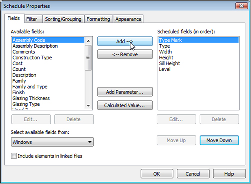
Adding Fields to a Schedule
www.sybex.com/go/revit2012ner. From there, you can browse to Chapter 11 and find the file called NER-22.rvt. The following procedure focuses on creating a door schedule. Grab a cup of coffee or a power drink, and follow along:
![]() Schedule/Quantities button, as shown in Figure 11.1.
Schedule/Quantities button, as shown in Figure 11.1.
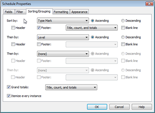
Sorting and Grouping
Controlling Headers
Modifying Elements in a Schedule
Modifying the Schedule’s Appearance
Adding a Schedule to a Sheet
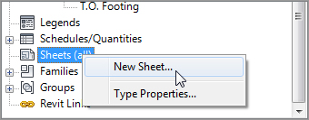
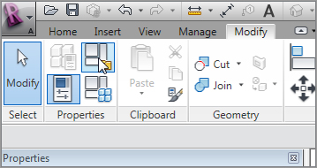
![]() Schedule/Quantities button. Note that you can also right-click Schedules in the Project Browser to create a new schedule.
Schedule/Quantities button. Note that you can also right-click Schedules in the Project Browser to create a new schedule. 
Creating Material Takeoffs
![]() Material Takeoff, as shown in Figure 11.25.
Material Takeoff, as shown in Figure 11.25. 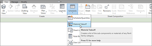
Creating a Calculated Value Field
![]() Duplicate, as shown in Figure 11.31.
Duplicate, as shown in Figure 11.31.

Creating Key Legends and Importing CAD Legends
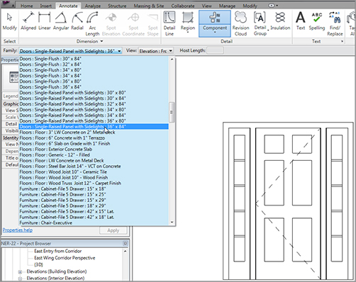
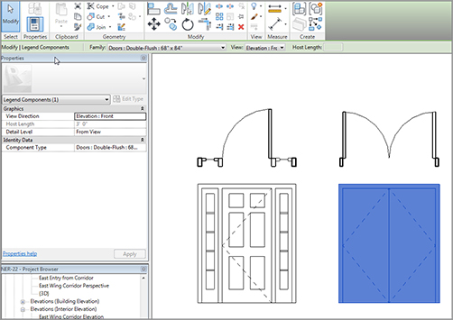
Adding Legend Components
![]() Legend button, as shown in Figure 11.39. You can also right-click Legends in the Project Browser and pick New Legend.
Legend button, as shown in Figure 11.39. You can also right-click Legends in the Project Browser and pick New Legend. 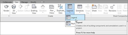
![]() Legend button on the View tab.
Legend button on the View tab.
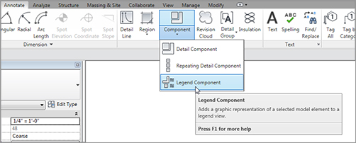
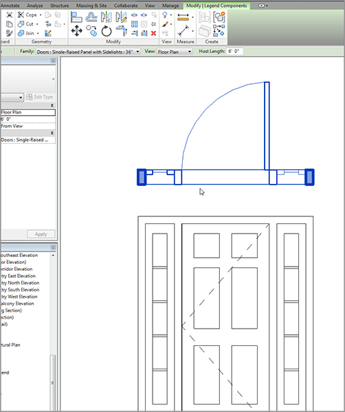
![]() Legend Component button, as shown in Figure 11.41.
Legend Component button, as shown in Figure 11.41.
Adding Symbols to a Legend
Using the Revit Symbols
![]() Legend button.
Legend button.
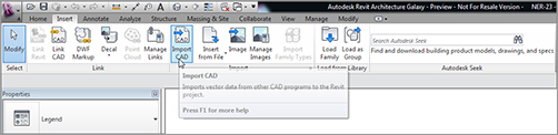
Importing AutoCAD Legends
.dwg and .dgn files just fine. Of course, there will be some tweaking, but when you get the process down, I think you’ll rely heavily on this functionality.
www.sybex.com/go/revit2012ner. From there, you can browse to Chapter 11 and find the file called Interior Partition Legend.dwg. Place the drawing file on your system in a place where you can retrieve it later. Now, perform the following steps:
![]() Legend button.
Legend button.
.dwg file called Interior Partition Legend.dwg.
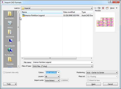
.dwg file into Revit.
![]() Full Explode, as shown in Figure 11.58.
Full Explode, as shown in Figure 11.58. 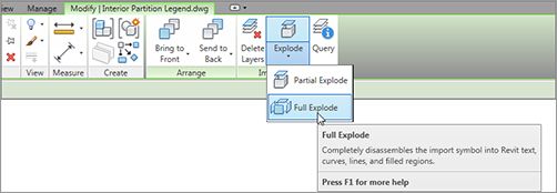
Adding Tags
Adding Tags Individually
Tagging by Category
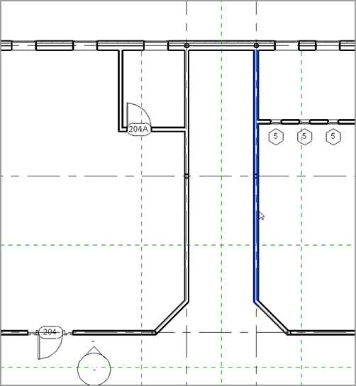
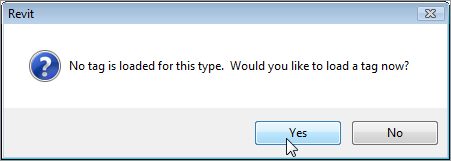
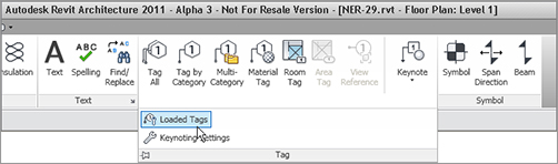
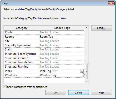
Tagging Walls
![]() Architectural
Architectural ![]() Wall Tag.rfa.
Wall Tag.rfa.
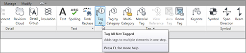
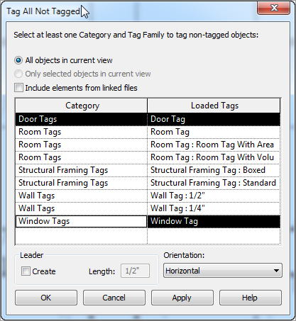
Using the Tag All Command
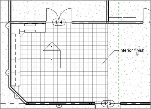
Tagging by Material
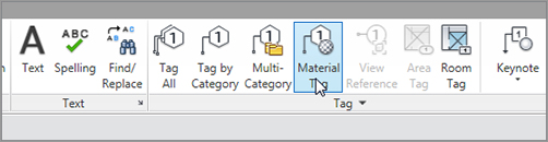
![]() Architectural
Architectural ![]() Material Tag.rfa.
Material Tag.rfa.
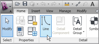
Creating Custom Tags
![]() Family.
Family.
Annotations folder.
Generic Tag.rft.
Casework Tag.rfa. Make sure you save the file in a location where you can locate it later.
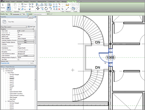
Using Multi-category Tags
![]() Family.
Family.
Annotations folder, locate the file called Multi-Category Tag.rft.
Multi-Category Tag.rft template.
![]() Family. Place the file somewhere you can find it later.
Family. Place the file somewhere you can find it later.
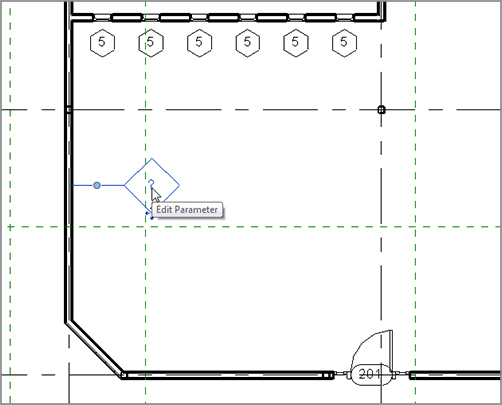
Keynoting
Keynoting by Element
keynote.txt file that Revit is pointing to. Then follow along:
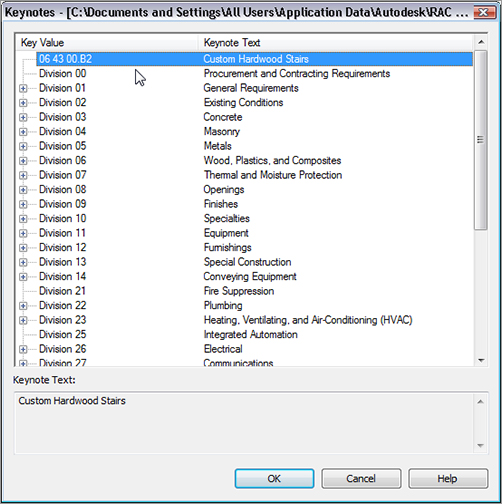
C:\ProgramData\Autodesk\RAC 2012\Libraries\US Imperial\RevitKeynotes_Imperial_2004.txt.
Keynote.txt file
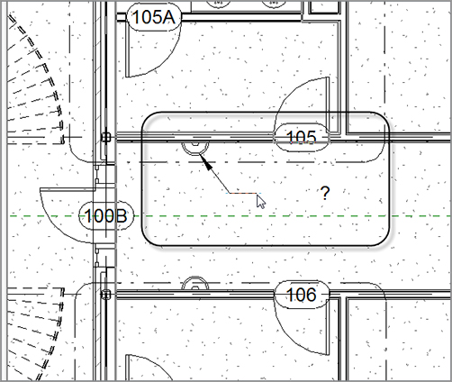
![]() Element Keynote, as shown in Figure 11.93.
Element Keynote, as shown in Figure 11.93. 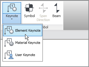
![]() Element Keynote.
Element Keynote.
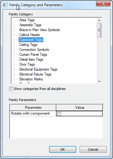
![]() Keynote Text, as shown in Figure 11.94.
Keynote Text, as shown in Figure 11.94. 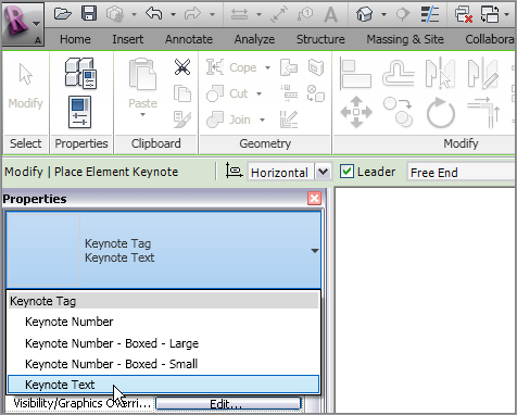
![]() Keynote Text
Keynote Text
![]() Element Keynote again.
Element Keynote again.
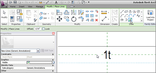
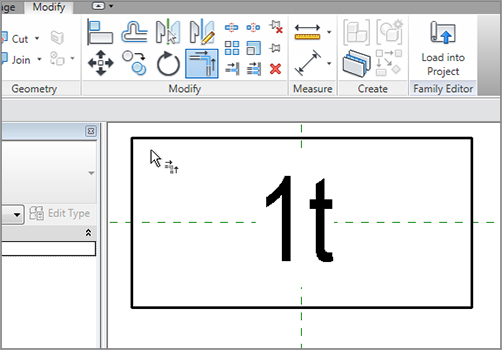
Keynoting by Material
![]() Material Keynote.
Material Keynote.
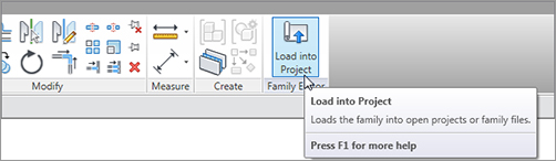
Keynoting by User
C:\ProgramData\Autodesk\RAC 2012\Libraries\US Imperial\RevitKeynotes_Imperial_2004.txt(RevitKeynotes_Metric.txt).
![]() User Keynote.
User Keynote.
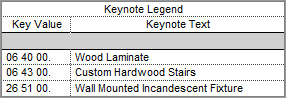
Creating Keynote Legends
![]() Keynote Legend.
Keynote Legend.
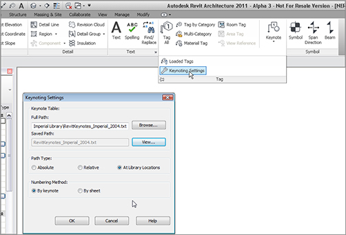
Keynote Settings
Are You Experienced?
Now you can…