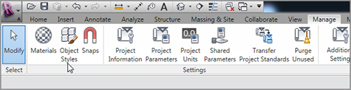
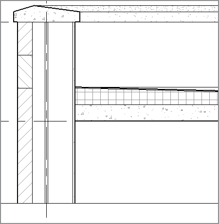
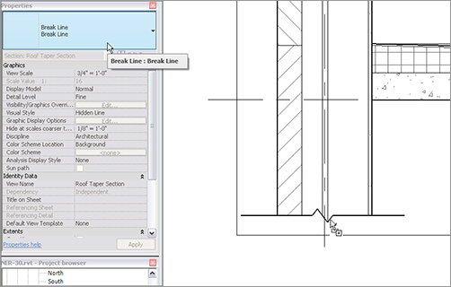
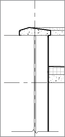
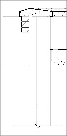
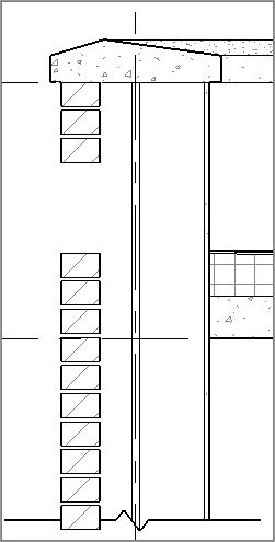
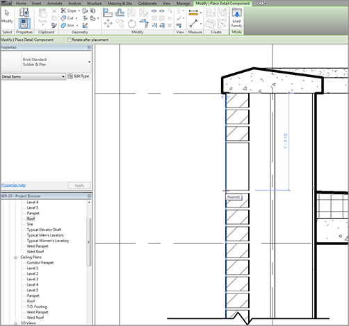
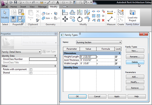
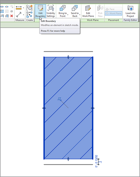
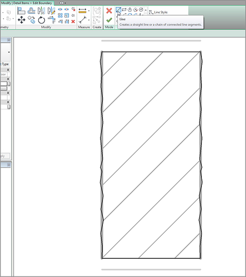
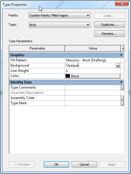
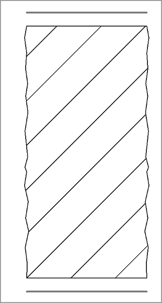
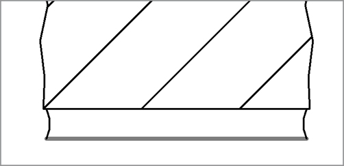
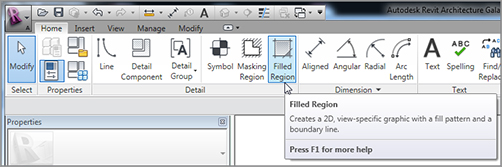
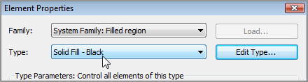
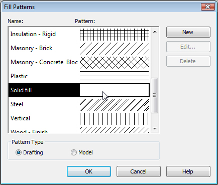
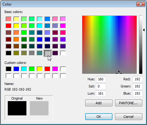
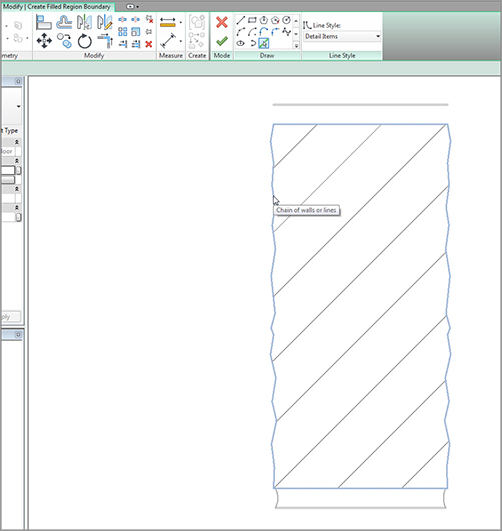
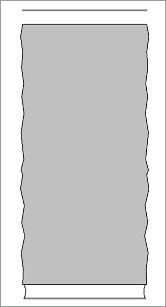
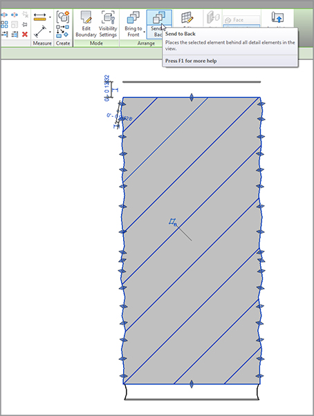
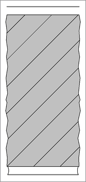
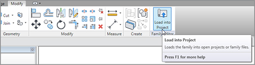
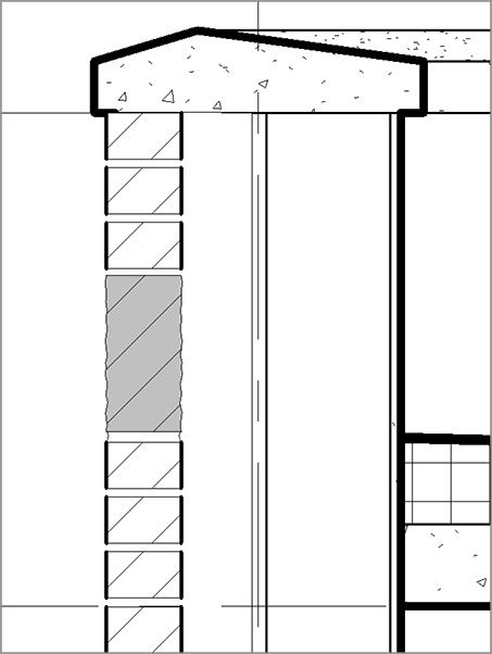
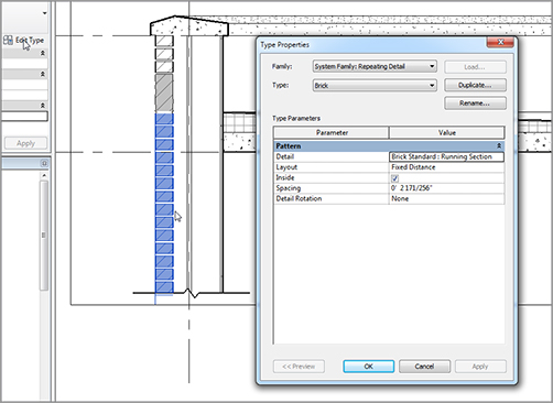
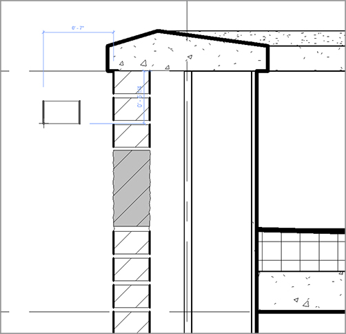
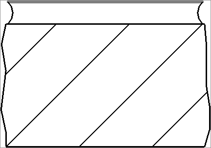
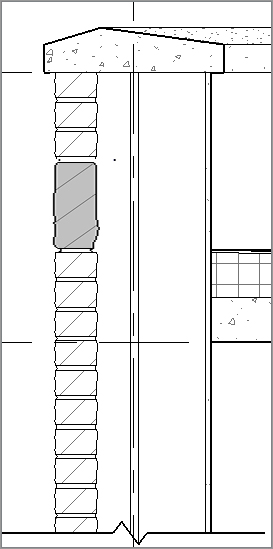
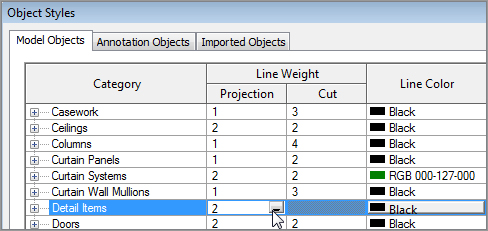
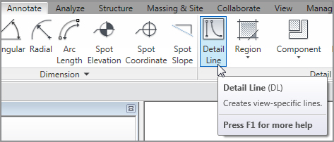
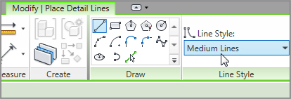
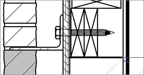
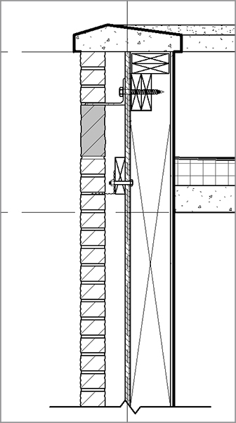
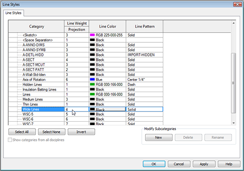
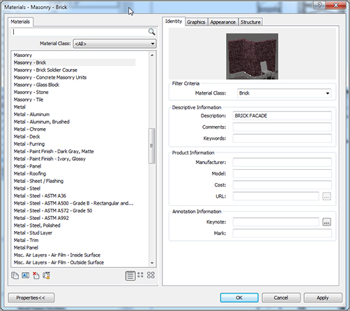
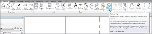
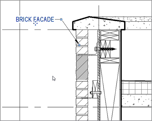
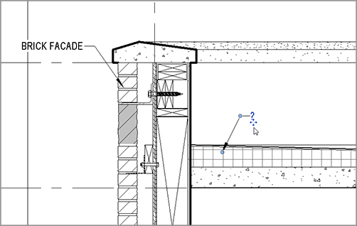
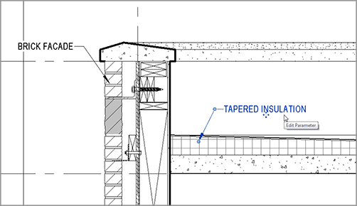
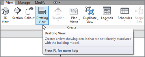
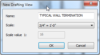
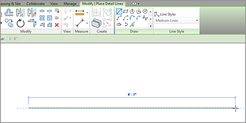
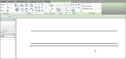
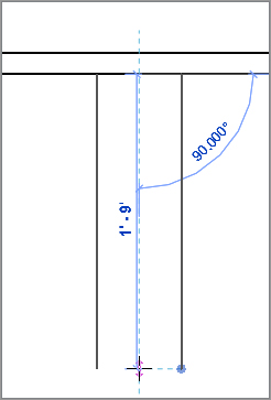
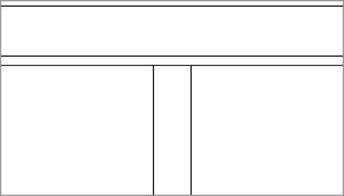
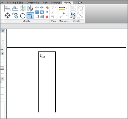
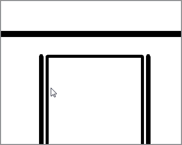
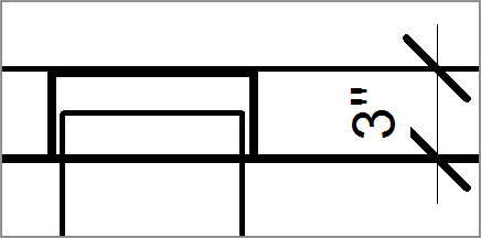
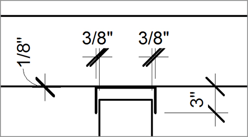
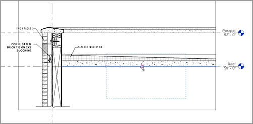
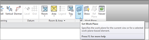
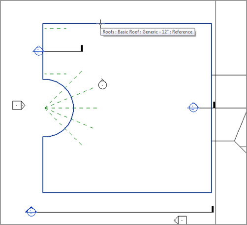
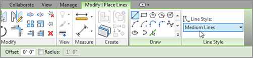
Simply put, if detailing doesn’t work, then you’ll use Revit only as a schematic design application. It’s imperative that you can detail in Revit efficiently. When firms fail in the attempt to use Revit, it’s because of detailing. In fact, many of you who have bought this book may jump straight to this chapter. And why is that? It’s because many people (including me) buy into the concept of really cool 3D perspectives and one-button modeling. So, here’s what we are going to tackle in this chapter: When you understand Revit, you find out immediately that the real hurdle in getting it to work lies in the detailing. Sure, you can cut sections and create callouts, but how do you add that fine level of detailing needed to produce a set of documents that you’re willing to stamp and sign? This chapter addresses the issues surrounding detailing. The first thing that comes to mind when dealing with CAD standards is line weights, right? In AutoCAD it’s layers, in MicroStation it’s levels, but on paper it’s line weights that control 75 percent of a company’s standards. As you’ll learn in this chapter, Revit can be a good 2D drafting application as well. As you learn how to control line weights in the 3D elements, you can also control line weights, well, line by line. To begin, open the file you’ve been following along with. If you didn’t complete the previous chapter, go to the book’s web page at The objective of this procedure is to format the line weights and to see where, and how, they’re read by Revit: FIGURE 12.1 Object Styles is located at left on the Manage tab. FIGURE 12.2 Changing the object line weights Glancing up at the headers that describe the columns, you see the Line Weight column. This column is divided into two sections: Projection and Cut. The Projection column controls the line weights of objects as they’re viewed in plan or elevation. The Cut column controls the line weights as they’re shown in section. So, to reiterate, projection means plan and elevation, and cut means section. Your objective is to modify the line weight for both the cut and the projection of the roof. FIGURE 12.3 Your section’s outline should begin looking a lot better. Now you can start adding your own items to the section. The next group of procedures focuses on inserting and creating detail components to use in the sections. As mentioned before, Revit provides a good number of 2D details that you can insert at any time. When Revit doesn’t have the component you need, you can always create one. It isn’t that hard to do. In this section, you’ll physically create a detail. The procedures you’ll apply consist of adding detail components, linework, and filled regions, and doing some good old-fashioned drafting! The first procedure focuses on inserting predefined detail components. The great thing about this is that you do nothing that you haven’t done repeatedly throughout this book—it’s just a matter of finding the right button to get started: FIGURE 12.4 The Load Family button on the Mode panel of the Modify | Place Detail Component tab The next step is to simply start drafting. As mentioned earlier, you’re only going to get so far with 3D modeling before you have to take matters into your own hands and draft. The way you can approach this in Revit is to take the parts of the detail you want to keep and hide the rest. After you hide portions of the detail, it’s time to begin adding your own ingredients such as detail components and lines. FIGURE 12.5 Placing the break line, and flipping the component To let you hide portions of the detail, Revit has added a nice feature called a masking region. Instead of wrestling around with items you ultimately have little or no control over, you can hide these items to make way for your detailing. To learn how to apply a masking region, follow these steps: FIGURE 12.6 Region The area is now masked. The problem is, though, that some areas such as the break may be a little too masked. The next procedure steps through changing the display order of a detail’s objects: FIGURE 12.7 Click the Rectangle button on the Draw panel, and place a masking region as shown. Your detail should now look like Figure 12.9. The next step is to add a brick face. Yes, Revit showed the brick before you masked it, but you need to show coursing, as well as how the façade is tied back to the wall. To do this, you’ll use a function called a repeating detail. FIGURE 12.8 Click the Bring To Front button on the Modify | Detail Items tab after selecting the break line. FIGURE 12.9 The detail with the completed masking region Revit has a technique that allows you to add a detail component as a group. You do this by basically drawing a line; Revit then adds the detail in an array based on the points you pick. To learn how to add a repeating detail, follow this procedure: FIGURE 12.10 Select Component FIGURE 12.11 Adding the repeating detail based on the points shown Your detail should look like Figure 12.12. FIGURE 12.12 The first repeating detail Next, you’ll keep going with the repeating detail. The problem you’re faced with is that you need to deal with the soldier course in the exterior wall. You can add that in a moment. Right now, complete the brick down past the break line. If you feel like you’re getting the hang of adding the repeating brick detail, go ahead and add the second repeating detail. If you would like some instruction, follow along: FIGURE 12.13 Picking two points FIGURE 12.14 The bricks are being placed. The next step is to add the soldier course. You’ll do this the same way you added the break line. In this respect, Revit offers a good library broken down into the CSI format. To add the soldier course, follow along with the procedure: FIGURE 12.15 Placing the new detail component Well, the soldier course is in place, but that fat line weight is horrendous. It would be nice if everything that came out of the Revit box looked nice and met your specifications; but alas, that isn’t the case. It’s time to modify this component to make it look presentable. Right about now is when every CAD/BIM manager around the globe raises an eyebrow—for good reason. Revit allows you to modify a component by actually opening the file! But don’t worry; you have to issue a Save As to save the detail. The objective of the following procedure is to create a texture on the brick detail and to use a line weight that the user can control in the model: FIGURE 12.16 Open the family for editing after selecting the detail component. The detail component family is now open. It’s time to operate, Doctor. The next set of procedures will focus on modifying the linework of the brick and adding what is called a filled region. A filled region is similar in nature to a masking region in that you apply both in the same manner. A filled region, however, contains a hatch pattern that is visible when the region is completed. This is how you hatch in Revit. It takes the place of the conventional hatch command found in AutoCAD and MicroStation. The objective of the next procedure is to modify the filled region that makes up the brick. You’ll also use the region’s outline to define the perimeter and the texture of the brick itself: FIGURE 12.17 Cleaning out the extra types FIGURE 12.18 Editing the boundary of the filled region FIGURE 12.19 Adding a texture to the brick family FIGURE 12.20 Changing the background to Transparent FIGURE 12.21 The finished soldier Now it’s time to add a mortar joint to the bottom of the brick. You simply add drafting lines: FIGURE 12.22 Adding the mortar joint The next step is to add shading underneath the brick pattern. To do this, you’ll create an entirely new filled region and add it to the brick by tracing over the existing filled region: FIGURE 12.23 Click the Filled Region button on the Detail panel. FIGURE 12.24 Changing the region to Solid Fill – Black FIGURE 12.25 Select the Solid Fill pattern, and click OK. FIGURE 12.26 Selecting the gray color (RGB 192-192-192) FIGURE 12.27 Press Tab to select the chain of lines, as shown here. FIGURE 12.28 The solid pattern covers the previous pattern. You’ll fix this in a moment. FIGURE 12.29 Sending the light shade to the back FIGURE 12.30 The finished brick FIGURE 12.31 The Load Into Project button FIGURE 12.32 The new soldier brick in the model The next group of procedures focuses on editing the bricks used in the repeating detail. You certainly want the same face texture, and it would be nice if there was a mortar joint between them. Before you modify the bricks, let’s explore how a repeating detail is created. The objective of the next procedure is to discover how a repeating detail works and how you can create a new one: FIGURE 12.33 Click the Edit Type button after selecting one of the brick repeating details. You can change the spacing and the patterns of how the repeating detail will perform. The next objective is to modify the specific detail component that the repeating detail is using. To do so, you must add an instance of the detail component (in this case, it’s Brick Standard : Running Section) and then edit the family. After you load it back into the model, the repeating detail will be up to date. If you would like to give it a shot and do it on your own, go ahead. If you would rather have some guidance, follow along: FIGURE 12.34 Place the Brick Standard : Running Section detail component off to the side. You’ll delete this occurrence of the component later. FIGURE 12.35 Draw the textured face while you’re in the Edit mode for the filled region. Draw the arcs for the mortar joint using lines. Compare your detail to the detail in Figure 12.36. FIGURE 12.36 The brick actually looks like brick! Next, you’ll anchor this façade back to the wall. Two things need to be added: a structural relief angle above the soldier course, and a brick tieback to a lower course. Follow along: FIGURE 12.37 Placing the L6X4X5/16 angle Of course, the line weight is basically a blob, so you must modify the family in order for it to look accurate. The next procedure is almost a review of what you had to do to the bricks: FIGURE 12.38 The angle in place and looking like an angle The next step is to find a fastener to anchor the angle back to the wall’s substrate. There is a problem, however. The type of bolt you need is a lag bolt that is power-driven from the exterior into the wall. Revit doesn’t provide one out of the box. Luckily, the book you bought does! To find the lag bolt provided with the book, go to the book’s web page, browse to Chapter 12, and find the file FIGURE 12.39 Inserting the lag bolt Next, you’ll add a corrugated wall tie to the brick below the soldier course. Because the brick is a pretty good distance away from the wall, you first need to add some wood blocking to the model: FIGURE 12.40 Adding the wood blocking The next step is to add the corrugated wall tie. You’ll do this in the same manner, except that it’s located in a different directory: FIGURE 12.41 Placing the corrugated wall tie Now you’ll add some blocking along the concrete parapet cap. You also need additional blocking along the lag bolts. If you would like, go ahead and copy the 2×6 blocking around the model to mimic the figure at the end of this series of steps. Or you can follow along: FIGURE 12.42 Rotating the blocking after copying it When you’re drafting over a true section of your model, it’s always good to try to use as much of the graphical information from the actual model as possible. For example, the 3/4˝ void you see the bolt going through is actually 3/4˝ plywood sheathing. For some reason, the default plywood material has its cut pattern set to None. Let’s fix this: FIGURE 12.43 Copy the blocking as shown. Now that you have a good grasp of adding detail components, you need to learn how to control the line weight so the outlines of the bricks look a little bolder. FIGURE 12.44 Show us your plywood! If you remember, some of the detail components were modified based on the line weight of the filled region perimeter. This thickness was changed from Heavy Lines to Detail Items. You need to set Detail Items to a thickness you can live with: FIGURE 12.45 Changing the Detail Items Projection line weight to 2 Another item left to explore in terms of adding detail to a view is the simple concept of drawing lines. As mentioned before, in Revit you can simply draw lines. You can only get so far with detail components, and then you need to pick up the pencil and add your lines. The next set of procedures will focus on adding lines to your model. Then, we’ll look deeper into how these lines are created and modified: FIGURE 12.46 Click the Detail Line button on the Annotate tab. FIGURE 12.47 Select the Medium Lines choice in the Lines Style menu. FIGURE 12.48 Drawing a medium line FIGURE 12.49 Offsetting the line down 1 1/2˝ to create a second line So, what makes a Medium Line medium and a Thin Line thin? This is a part of Revit that you need to have full control over. After all, your biggest challenge will be getting your plotted sheets to match your old CAD plotted sheets. Specifying line weights is crucial. Just as in CAD, you wouldn’t dare to draw even a single line if you didn’t know the proper layer it was being drafted on, right? Why should Revit be any different? The objective of the next procedure is to investigate where the line weights are stored and how they relate to the lines you’re drawing: Some of the line styles were generated in AutoCAD. These line styles were imported when you brought in the legend back in Chapter 11, “Schedules and Tags.” FIGURE 12.50 Adding the detail to indicate studs and plates by using detail lines The next item to tackle is the fact that this detail looks naked without any text or dimensions added to it. Although you’ve applied both of these items in past chapters, you need to use them as they’re relevant to detailing. FIGURE 12.51 Changing Wide Lines from 5 to 4 In Revit, adding notes to a section can take on a whole different meaning than in CAD. You may remember back in Chapter 11 when you were able to specify materials and then tag them in a plan. Well, you can do the same thing in Revit. Or, if you wish, adding notes to a detail can be exactly as it was back in CAD. Sometimes, sticking to the tried-and-true isn’t such a bad thing. The objective of the next set of procedures is to add notes by tagging materials, and to add notes by simply leadering in some text. Because you have some experience adding information to materials, let’s use that experience here. The next procedure will involve going to the material settings and adding a description to the brick that reads BRICK FACADE. Then, you’ll add that tag in the section. If you’re confident, you can do this on your own. Your finished detail should look like the Figure 12.54. If you would like some instruction, follow along: FIGURE 12.52 Changing the Description to BRICK FACADE in the Identity tab FIGURE 12.53 On the Annotate tab, click the Material tag button on the Tag panel. FIGURE 12.54 Placing the material tag Another method of applying a description to a material is to tag the item first and then fill out the tag. If you do so, the material will automatically be identified, and the tag will be filled out the next time you tag the same material: FIGURE 12.55 Adding a material tag to the insulation Now it’s time to add some freeform notes. The great thing is, you’ve already done this, and you’ve gone as far as setting up your own leaders for that text. FIGURE 12.56 Add the note TAPERED INSULATION. We’re duplicating efforts with text to drive home the fact that Revit lets you add text indiscriminately of the view, and also indiscriminately of the scale. Text in a plan is the same as text in a detail. And we’ll prove it in the next procedure: FIGURE 12.57 Adding the leadered text These steps are the most common procedure for adding detail to a model. In other words, take what you can from the model, and then add linework and detail components to the view. But eventually you’ll find yourself in a situation where you would rather draft your detail from scratch. You can do this as well, as you’ll see in the next section. FIGURE 12.58 Wrapping the text Over the years, Revit has been labeled as a “poor drafting application.” This is unfortunate, because it can be a very good drafting application when given the chance. The only challenge is to figure out where to start! The objective of the next procedure is to create a blank view and then learn how to simply draw lines: FIGURE 12.59 Click the Drafting View button on the View tab. FIGURE 12.60 Changing the view name and scale You’re now in a completely blank canvas. Anything you draw here is truly drafting and isn’t tied back to the model whatsoever. The objective of the next procedure is to start adding lines and more detail components. The item you’ll draft is a detail showing a flexible top track of a metal stud partition: FIGURE 12.61 Drawing a detail line approximately 4´–7˝ FIGURE 12.62 Using Pick Lines and adding an offset of 1 1/2˝ FIGURE 12.63 By setting an offset of 3˝, you can draw two lines using a common centerline. FIGURE 12.64 The detail up to this point FIGURE 12.65 Trimming the corners The next step is to add the track to the bottom of the floor. You’ll do this by creating three wide lines. The trick is to do a good amount of offsetting. If you want to explore and try the procedure on your own, try to match Figure 12.68 dimensionally. Remember, you’re using wide lines for the track. If you would rather have guidelines, follow these steps: FIGURE 12.66 Offsetting the heavy lines 3/8˝ to the right and to the left FIGURE 12.67 Offsetting the thick lines FIGURE 12.68 The top track is now in place. It’s time to add the gypsum to both sides of the wall. By using the same method as before, you’ll use thin lines to denote two layers of 5/8˝ gypsum on both sides of the stud. If you’re ready to complete this task on your own, go ahead. (Remember, you’re adding two layers of 5/8˝ gypsum to both sides of the wall, and you’re using thin lines to denote this.) If you would rather have some guidelines to practice with, let’s step through the procedure: FIGURE 12.69 Adding the lines for the gypsum Look at this: the steps are getting shorter. You used only the Detail Line command but have successfully offset every line you needed without leaving the command you were running at the time. Who says you can’t draft in Revit? The next procedure will involve adding a filled region to the “floor.” Although you don’t want to be too specific about what you’re calling out, you still need some contrasting hatch. If you would like to venture out on your own, try to duplicate Figure 12.71. You’ll need to add a filled region using diagonal lines. If you would rather follow the procedure, let’s get started: FIGURE 12.70 Draw the filled region with Invisible Lines. FIGURE 12.71 The detail with the hatching included This detail is looking good—so good that it would be nice to never have to draw it again. Let’s proceed with creating a special group that you can drag onto another view. Groups can be extremely advantageous to the drafting process. Although I mentioned earlier that details and drafting views aren’t linked to the model, you can still provide some global control within the details themselves by creating a group. This will give you further control over every instance of this specific detail within the entire model. The objective of the following procedure is to create a new group and add it to another view: FIGURE 12.72 The Create Group button on the Create tab FIGURE 12.73 Move the origin to the location shown here. With the group created, it’s time to add it to another view. Because not every view shows exactly the same thing, you can alter the group’s instance to conform to the detail into which it’s being placed. The objective of this next procedure is to physically add the new detail group to the Roof Taper Section: FIGURE 12.74 Choose Place Detail Group. FIGURE 12.75 Picking a point along the bottom of the roof to place the group The next step is to remove some of the extraneous hatch and lines. You can do this within a group, but you must be careful not to edit the group in a way that affects all other instances. The objective of the next procedure is to remove the extra lines and hatch from the group: FIGURE 12.76 Excluding an element from the group FIGURE 12.77 The slip track without the extra lines Now you’ll make modifications to the original group to see how each insertion of a group is influenced. This is where the advantage of using groups in a model comes into play. The objective of the next procedure is to open the original group and modify it. When the modifications are completed, the other groups will be updated: FIGURE 12.78 The Insulation button on the Detail panel of the Annotate tab You’re starting to get detailing pretty well. There are two issues left to discuss. First, it would be nice to reference these details from the plan, even knowing that they aren’t physically tied into the model. Second, you need to know how to import CAD into a detail. FIGURE 12.79 Drawing the insulation FIGURE 12.80 The Finish button on the Edit Group toolbar You already know how to add a section marker in plan. What you may not know is how to tell Revit that you would rather specify the reference. The objective of the next procedure is to go to the Level 1 ceiling plan and add a section pointing to your drafting view: FIGURE 12.81 Choosing the correct options while placing the section With creating a drafting view behind us, it’s time to look at our old friend CAD. (Some may say the new acronym is Ctrl Alt Delete.) Regardless of the existing sentiment toward CAD, it did get us this far. And we still need it—more so in the drafting capacity. Yes, you can import CAD into a detail. I’ll go out on a limb and venture to guess that you have a handful of CAD details that you use on a daily basis. The question always is, “What do I do with this pile of details I spent years, and thousands of dollars, to create?” Well, you can still use them. The objective of the next procedure is to create a new drafting view and import an AutoCAD detail. If you would like, you can attempt to import your own detail, or you can use the file provided. Just go to the book’s web page at The objective of this procedure is to import a CAD detail into a drafting view: Up to this point, you’ve been using detail lines for your drafting. The one issue is that detail lines are visible only in the specific view you’re working in. Suppose you wanted linework to show up both in plan/elevation as well as a 3D view. In this situation, you should use the actual Lines tool. Just because you’re drafting, that doesn’t mean you can’t create lines in all views such as in a 3D view in a 3D function. Revit has a tool that is simply called Lines, and you use it to project lines into multiple views. You apply the Lines tool just like a detail line, only it behaves the same as a Revit 3D family in that you can see it in every view (unless you turn it off). The objective of the next procedure is to add detail lines to the west sloping roof. They’re nothing fancy, but you’ll quickly get the picture of how to use this feature: FIGURE 12.82 The Set button on the Work Plane panel of the Home tab FIGURE 12.83 Picking the roof. Your work plane is now set to slope with the roof. Anything you draw will be on this sloping plane. FIGURE 12.84 Click the Medium Lines button under Line Style. It’s a good idea to keep this feature in mind. This drafting tool will become useful when it comes to sketching in 3D. There will be many situations in which you’ll use this little nugget. FIGURE 12.85 Drawing an 80´–0˝ radius arc
CHAPTER 12
Detailing
Working with Line Weights
www.sybex.com/go/revit2012ner. From there you can browse to Chapter 12 and find the file called NER-23.rvt.
Drafting on Top of the Detail
Using Predefined Detail Components
![]() Detail Component, and then click the Load Family button as shown in Figure 12.4.
Detail Component, and then click the Load Family button as shown in Figure 12.4. 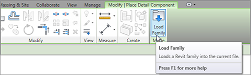
Detail Components directory. (It’s located in the US Imperial Library directory.)
Div 01-General folder.
Break Line.rfa.
Masking Regions
![]() Masking Region, as shown in Figure 12.6.
Masking Region, as shown in Figure 12.6. 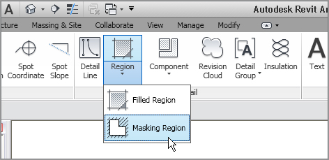
![]() Masking Region on the Annotate tab
Masking Region on the Annotate tab
Repeating Details
![]() Repeating Detail Component, as shown in Figure 12.10.
Repeating Detail Component, as shown in Figure 12.10. 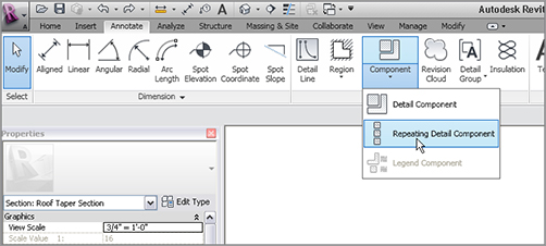
![]() Repeating Detail Component.
Repeating Detail Component.
![]() Repeating Detail Component button on the Detail panel on the Annotate tab.
Repeating Detail Component button on the Detail panel on the Annotate tab.
![]() Detail Component button.
Detail Component button.
Modifying a Detail Component
Modifying Filled Regions
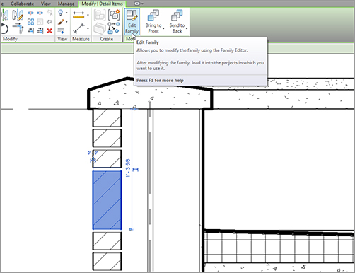
![]() Family.
Family.
Light Shade.
![]() Detail Component button.
Detail Component button.
Brick Standard.rfa.
![]() Detail Component button.
Detail Component button.
Detail Components folder.
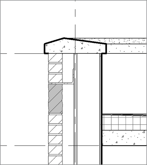
Div 05-Metals.
051200-Structural Steel Framing.
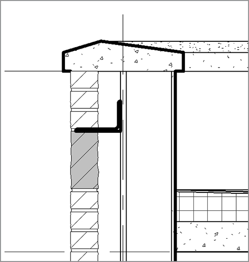
AISC Angle Shapes-Section.rfa.
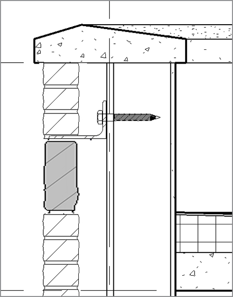
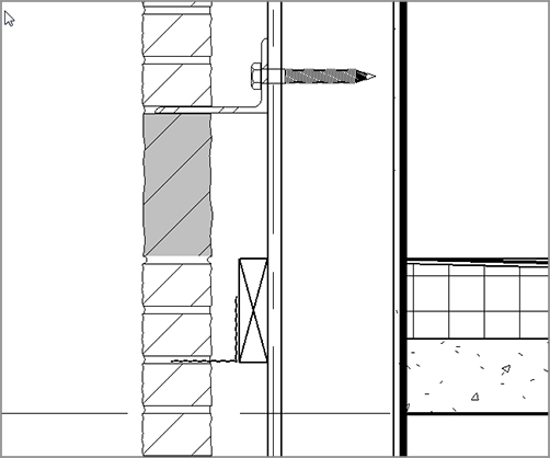
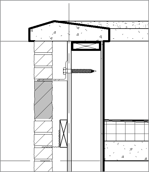
A307 Lag_Bolt-Side.rfa. Then, follow along:
A307 Lag_Bolt-Side.rfa file. Find the file and click Open.
![]() Detail Component button on the Annotate tab.
Detail Component button on the Annotate tab.
Detail Components folder.
Div 06-Wood And Plastic.
061100-Wood Framing.
Nominal Cut Lumber-Section.rfa.
![]() Detail Component button, and place the 2×6 into the wall, as shown in Figure 12.40.
Detail Component button, and place the 2×6 into the wall, as shown in Figure 12.40. 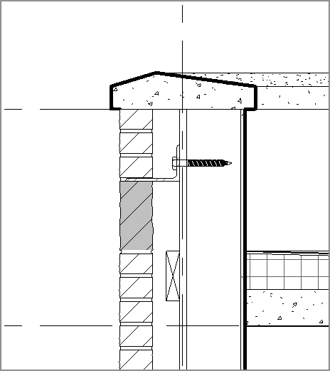
![]() By Element.
By Element.
Detail Components folder.
Div 04-Masonry.
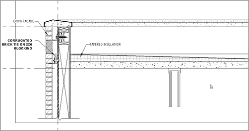
040500-Common Work Results For Masonry.
040519-Masonry Anchorage And Reinforcing.
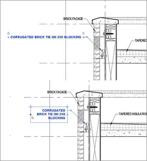
Corrugated Wall Tie-Section.rfa.
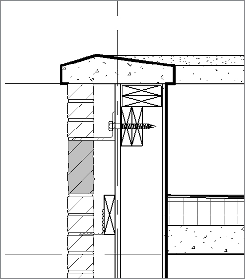
![]() By Element. Change the projection line weight to 2.
By Element. Change the projection line weight to 2.
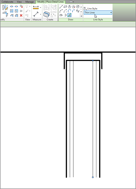
Drawing Detail Lines
Specifying Drafting Line Weights
![]() Line Styles.
Line Styles.
Adding Notes
Adding Notes by Material
Adding Textual Notation
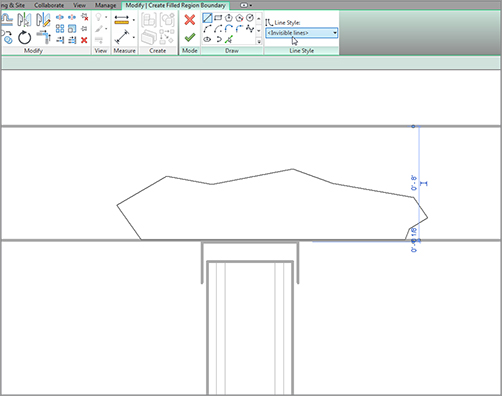
Creating Blank Drafting Views
![]() Filled Region button.
Filled Region button.
Creating a Detail Group
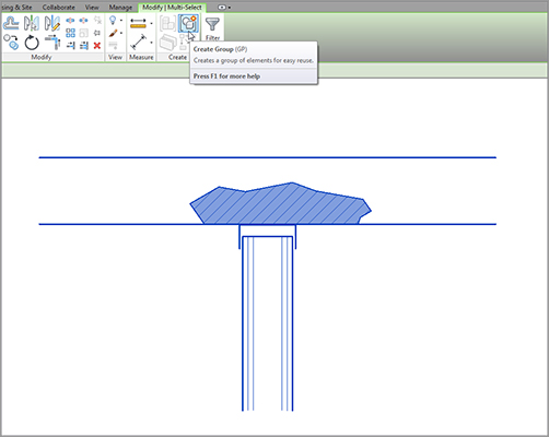
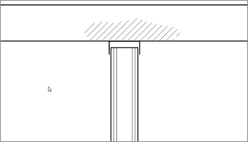
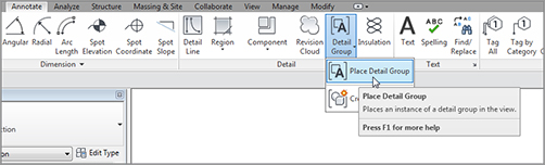
![]() Place Detail Group, as shown in Figure 12.74.
Place Detail Group, as shown in Figure 12.74.
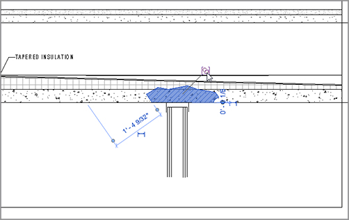
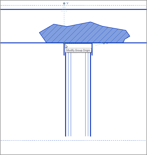
Adding a Section to Another View
Importing AutoCAD into a Drafting View
www.sybex.com/go/revit2012ner. From there, you can browse to Chapter 12 and find the file called base cabinet.dwg. You can then place it on your system for later retrieval.
![]() Full Explode.
Full Explode.
Adding 2D and 3D Lines to the Model
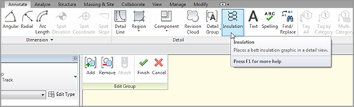
Are You Experienced?
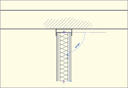
Now you can…