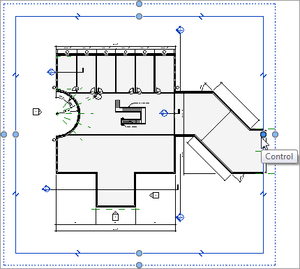
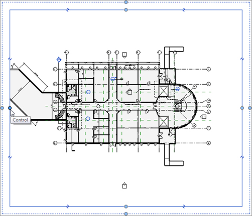
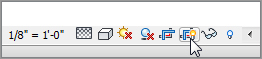
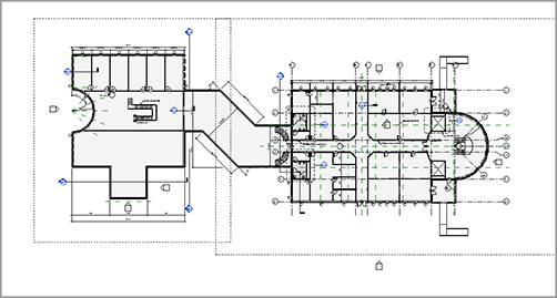
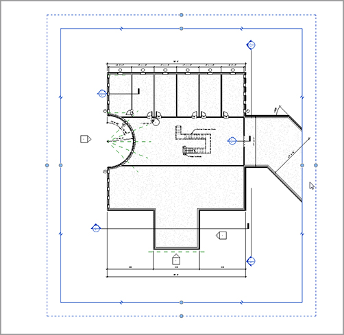
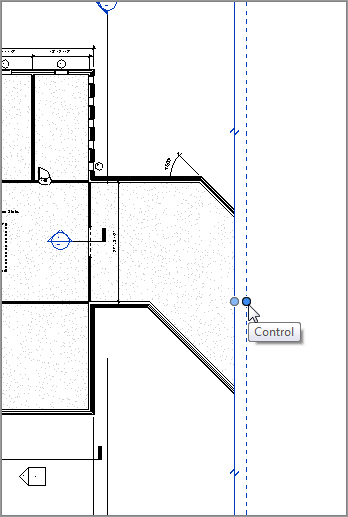
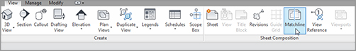
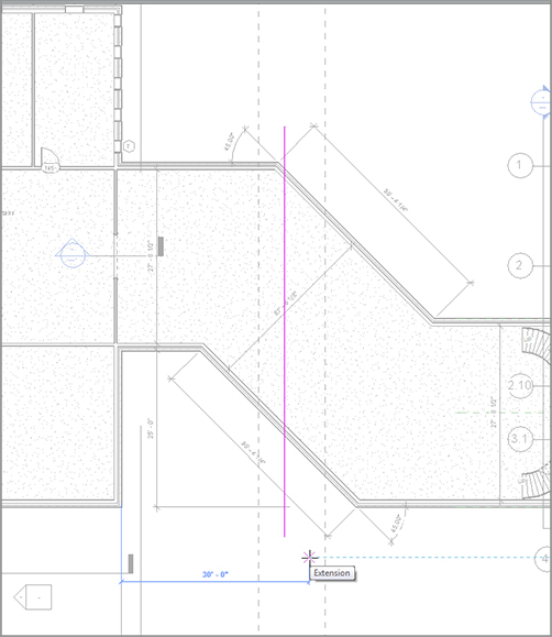
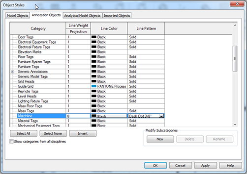
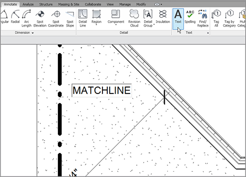
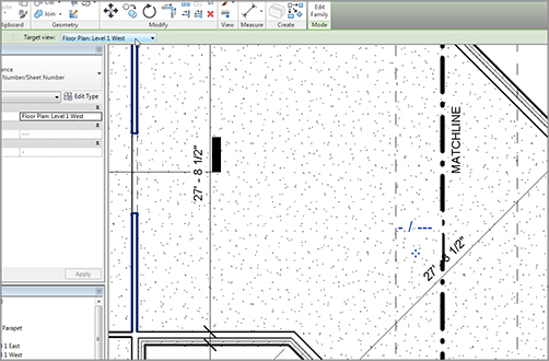
As you can see, Revit is all about the views. In fact, by using Revit, not only are you replacing the application you use for drafting, but you’re also replacing your existing file storage system. This is largely because you’re now using one model, and you are using views of that model for your project navigation. I wanted to dedicate an entire chapter to project navigation. Although you’ve steadily gained experience in this area, we can expand on much more to round out your Revit expertise. The first item we’ll tackle in this chapter is the process of duplicating a view to create another. Although it’s a straightforward procedure, a lot is riding on the hope that you proceed with this function correctly. As you’re about to find out, this command isn’t a simple copy-and-paste operation. Revit will change how you organize a project. You’ll no longer open a file and save it as another file so you can make changes without affecting the original. As you know, Revit is all-inclusive in terms of files. Well, there is only one. From that one file, there are views that reside within the Project Browser. Of course, I’m not telling you anything you haven’t learned. If you’ve gone through the book from page 1, you’ve already gained experience in creating views (especially in Chapter 3, “Creating Views”). If you’re just jumping to this chapter, you most certainly have had some exposure to view creation. The reason this topic is broken into two chapters is to help you gain a more in-depth understanding of how you can manipulate and organize views. Now, let’s duplicate some views! To begin, open the file you’ve been following along with. If you didn’t complete the previous chapter, go to the book’s web page at The objective of the following procedure is to create a furniture plan of Level 1 and then turn off the furniture on the original Level 1: FIGURE 13.1 Right-clicking the Level 1 floor plan in the Project Browser Now, any time you add furniture or casework, it will only show up in the furniture plan. You don’t need to deal with a layer or display configuration. The ability to create a copy of a view and then modify its visibility graphics to display certain items is a critical function in Revit. Another similar task is also available: creating coordinated match-line divisions in a model by creating dependent views. You create a dependent view in much the same way you duplicate a view. In fact, you are duplicating a view. The function of a dependent view is to “nest” a duplicate of a view within the host view (or the view you’re making the duplicate of). This nested view is dependent on the host view in terms of visibility graphics and View Properties. You can have multiple dependent views categorized under the host view. The reason you create dependent views is to add match lines. Yes, you could simply duplicate a view and move its crop region, but when you have dependent views—as you’ll see in Chapter 14, “Creating Sheets and Printing”—you can tag those views in a specific way for Revit to keep track of the sheets they’re on. Dependent views also give the advantage of making your Project Browser much less cluttered, without unnecessary floor plans. The objective of the next procedure is to make a dependent view of the Level 1 floor plan: FIGURE 13.2 Creating the two views dependent on Level 1 Now that the views are duplicated and nested within the host view, it’s time to divide the Level 1 floor plan. You’ll do this by adjusting the crop region. Every view in Revit has a crop region. Crop regions play an important role when your plan is too large to fit on a sheet. All you need to do at this point is to slide the east and west crop regions to display the correct views. The objective of the next procedure is to adjust the crop regions to display the appropriate parts of the plan based on the name of the views: FIGURE 13.3 Dragging the crop region in the Level 1 West view FIGURE 13.4 Dragging the crop region to the right in the Level 1 East view Now you can see the area where you need to draw the match line. The crop region should overlap in the corridor. If not, drag the crop regions so that they match Figure 13.6. FIGURE 13.5 Turning on the crop region from the View Control toolbar FIGURE 13.6 Adjusting the crop regions to overlap in the corridor Unfortunately, if you have a match-line situation in your project, you must follow this procedure with each floor plan separately. For multifloor projects, doing so can become time-consuming. Or you can right-click a view that has dependencies, and select Apply Dependent Views. From there, you can select which views the dependent views will be added to. As you can see, adjusting the crop region is how you specify which part of the plan will appear on your sheet. This poses one issue: if you have text that you would like to lie outside of the crop region—that is, if you have a leadered note pointing to an item within the cropped boundary—you may not see the note. To fix this, you can adjust the annotation crop region. Because the crop region cuts off the model at a specified perimeter, what is to become of text that needs to lie outside of this boundary? This is where the annotation crop region comes in handy. You’ll always have the situation where leadered text must be outside of the geometry it’s labeling. You can make adjustments to ensure that this can happen. The objective of the next procedure is to adjust an annotation crop region to clean up a plan. Follow along: FIGURE 13.7 Selecting the plan’s crop region. Notice the additional region on a dashed line type—this is the annotation crop region. FIGURE 13.8 Stretching the annotation crop region to the left Now that you understand how to add crop regions and display them appropriately, let’s add the match line. In CAD, adding a match line is nothing more than the simple practice of drawing a line. The same is true in Revit—only in Revit, you draw that line in Sketch Mode, and you can propagate the line to other views. Also, in Revit, after you place the line, it registers as having two sides of a model. In Chapter 14, when you drag your views onto sheets, Revit will know where each side of the model is in terms of being placed on a sheet. The objective of the next procedure is to place a match line into the model. Follow these steps: FIGURE 13.9 The Matchline button on the View tab Your match line appears as a bold dashed line. Because the physical appearance of a match line never seems to be the same from firm to firm, you can adjust the line’s appearance. A match line isn’t an actual line by definition; it’s an object. Therefore, you can control its appearance by using the Object Styles dialog. FIGURE 13.10 Placing the match line The next procedure focuses on changing the appearance of the match line: FIGURE 13.11 Changing the Matchline line pattern to Dash Dot 3/8˝ With the match line in place and the plan split into two halves, it’s time to add an annotation to label the match line. For the match-line annotation, you’ll place a piece of text that says MATCHLINE. But when you’re referencing each side of the plan, you’ll need to add view references. After the plan is split and the match line is in place, you can tag each side of the match line. When you drag the view onto a drawing sheet, the tag will be filled out with the correct page name. It’s important to note, however, that although this process is automatic, it isn’t fully automatic. You do need to specify the correct view name as you’re placing the tag. The objective of the next procedure is to place a piece of text that says MATCHLINE along the match line and to add a view reference to each side of the match line. Follow along: FIGURE 13.12 Typing the text MATCHLINE FIGURE 13.13 Adding a view reference includes choosing the correct target view from the Options bar. One last item to discuss before we close this chapter is how to create and use settings from a single view after you determine that you want to repeat the view settings. When you created the furniture plan in the beginning of the chapter, you manipulated the data in the Visibility/Graphics Overrides options to hide furniture in a specific plan. It would be nice to build settings like these into a template so you could simply apply that template to a view the next time the situation arose. The objective of the next procedure is to create a view template and apply it to another view. Follow these steps: FIGURE 13.14 Selecting the Without Furniture or Casework template As you can see, using view templates will help you immensely with maintaining company-wide standards. Use templates as often as possible.
CHAPTER 13
Creating Specific Views and Match Lines
Duplicating Views
www.sybex.com/go/revit2012ner. From there, you can browse to Chapter 13 and find the file called NER-24.rvt.
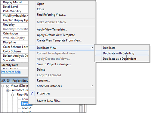
![]() Duplicate With Detailing, as shown in Figure 13.1.
Duplicate With Detailing, as shown in Figure 13.1.
Creating Dependent Views
![]() Duplicate As A Dependent. You now have a view that is nested under Level 1. As you can see, Level 1 is expanded to show its dependencies.
Duplicate As A Dependent. You now have a view that is nested under Level 1. As you can see, Level 1 is expanded to show its dependencies.
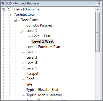
![]() Duplicate As A Dependent. You now have two views nested under Level 1 (see Figure 13.2).
Duplicate As A Dependent. You now have two views nested under Level 1 (see Figure 13.2).
Adjusting the Crop Regions
Adjusting the Annotation Crop Region
Adding Match Lines
Match-Line Appearance
Adding View References to a Match Line
Using View Templates

Are You Experienced?
Now you can…