Your deliverable product is a set of construction documents and specifications. So it stands to reason that the application you use to produce these construction documents is at its strongest in this arena. Unfortunately, when you see marketing campaigns related to Revit, all they show are huge skyscrapers and realistic renderings. And of course you see the slide of the architect handing a model to the contractor, and then the contractor handing it to the owner. Don’t get me wrong—all that stuff is good, but the most powerful feature of Revit Architecture is its ability to create sheets. You wouldn’t think this is the standout feature; but when it’s 4:30 in the afternoon and the job is going out the door at 5:00, you’ll never go back to a drafting application after you’ve used Revit at the eleventh hour.
The first part of the chapter will focus on creating a sheet and how to populate it with views. Although you completed this task back in Chapter 11, “Schedules and Tags,” it’s time to drill into the ins and outs of sheet creation.
Luckily, when you create and populate sheets, Revit holds true to form—that is, you don’t have to start setting up different drawings or models to simply reference them together. You create sheets much as you create most other views, because that is all a sheet is: a view. But a sheet goes one step further. Look at a sheet as a view that collects other views for the purpose of printing.
The objective of the following procedure is to create a new sheet. To get started, open the model you’ve been working on. If you missed the previous chapter, go to the book’s web page at www.sybex.com/go/revit2012ner. From there, you can browse to Chapter 14 and find the file called NER-25.rvt. Now, follow along:
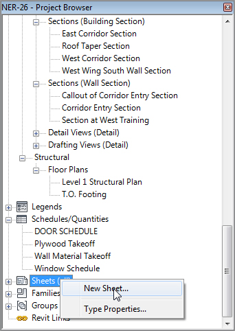
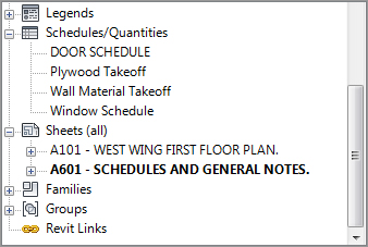
1. In the Project Browser, scroll down until you see a category called Sheets, as shown in Figure 14.1.
2. Right-click Sheets, and select New Sheet (see Figure 14.1).
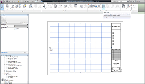
8. When the view is centered in the sheet, let go of the pick button. The view follows your cursor. Try to align the lower-left corner of the viewport with a guide grid, and then click. Doing so places the view onto the sheet.
This is how you populate a sheet using Revit—quite the departure from CAD. One nice detail is that the title is filled out, and the scale will never be incorrect. The next step is to begin renumbering sheets so you can create a logical order.
Sheet Organization
If you’ve been following along with the book, you already have a sheet numbered A101. It would be nice if you could give this sheet a new number and start your sequence over. Revit lets you do just that.
The objective of the next procedure is to change the sheet numbering and to add more sheets, allowing Revit to sequentially number the sheets as they’re created. Follow these steps:
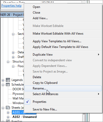
1. In the Project Browser, find the sheet A101 – Unnamed, and right-click.
With the sheets organized, you can now proceed to create more. As you do, you’ll see that not only do the sheets number themselves, but all of the sections, elevations, and callouts begin reading the appropriate sheet designations.
The objective of the next procedure is to create more sheets and to add views to them:
1. Right-click Sheets (All) in the Project Browser.
2. Select New Sheet.
3. Click OK to add the title block.
4. At the bottom of the Properties dialog, select 30 × 42 as the guide grid, as shown in Figure 14.6.
5. In the Project Browser, find the dependent view called Level 1 East, and drag it onto the new sheet.
6. Pick a point on the sheet to place the view aligned with the guide grid (see Figure 14.6).
7. In the Project Browser, double-click the A101 sheet, opening the view. Notice that the view reference next to the match line is filled out with the appropriate designation.
8. Double-click A102 to open the view again.
In the Project Browser, sheet A102 is still unnamed. The next procedure describes a different way to rename and renumber a sheet:
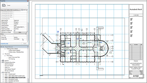
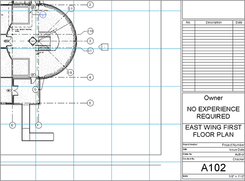
1. With Sheet A102 open, zoom into the right side of the view, as shown in Figure 14.7.
2. Select the title block. Notice that a few items turn blue. If you remember, any item that turns blue can be modified.
3. Click into the text that says Project Name, and type NO EXPERIENCE REQUIRED.
4. Click into the text that says Unnamed, and type EAST WING FIRST FLOOR PLAN (see Figure 14.7).
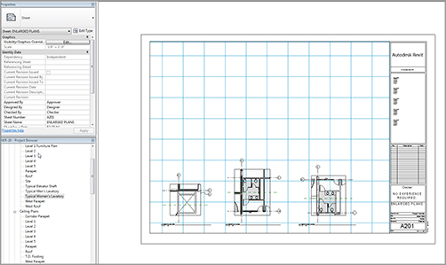
5. Create another sheet using the 30 × 42 Horizontal title block.
6. Number it A201.
7. Name it ENLARGED PLANS.
8. Add the 30 × 42 grid guide.
9. Drag the following views onto the sheet:
Typical Elevator Shaft
Typical Men’s Lavatory
Typical Women’s Lavatory
10. Arrange them so they’re in a row, as shown in Figure 14.8.
FIGURE 14.8 Creating a sheet and adding views in a row across the bottom of the page
Now that the first floor plans and typical enlarged plans are placed on a sheet, let’s move on to adding the details you’ve created.
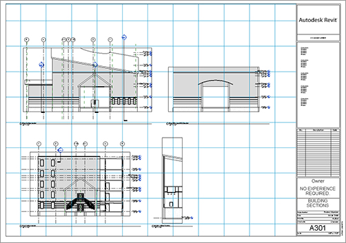
If you feel as though you have enough experience creating a sheet and adding views, go ahead and proceed on your own. Your new sheet will be numbered A301 and be called Building Sections, and you’ll add the views East Corridor Section, West Corridor Section, Section at West Training, and West Wing South Wall Section. Your sheet should look like Figure 14.9.
If you’d like some assistance in putting the section sheet together, follow along with this procedure:
1. In the Project Browser, right-click the Sheets category.
2. Select New Sheet.
3. Select the E1 30 × 42 Horizontal title block, and click OK.
4.In the Project Browser, right-click the new sheet, and select Rename.
5. Give the new sheet the number A301 and the name BUILDING SECTIONS.
6. In the Properties dialog, add the 30×42 grid guide.
7. In the Project Browser, find the Sections (Building Sections) category.
8. Drag the section called East Corridor Section onto the lower-left corner of the sheet.
9. Drag the section called Section at West Training onto the sheet to the right of the East Corridor Section.
10. Drag the section called West Corridor Section onto the sheet, and place it into the upper-left corner. Be sure you align it directly above the East Corridor Section.
11. Drag the section called West Wing South Wall Section to the right of the West Corridor Section and directly above the Section at West Training. The alignment lines allow you to accurately place the section. After you have these four sections in place, your sheet A301 should look like Figure 14.9.
You’ve created a few sheets, and you may want to make some adjustments to the view without leaving the sheet. The next section of this chapter will focus on the properties of a viewport and how to make it live on the sheet so you can make modifications.
Wait a second. Isn’t a viewport AutoCAD vernacular? Yes, it is. But a viewport in AutoCAD and a viewport in Revit are two completely different things.
In Revit, when you drag a view onto a sheet, a linked copy of that view becomes a viewport. This is what you see on the sheet. Any modification you make to the original view will immediately be reflected in the viewport, and vice versa. See Figure 14.10 for a graphical representation.
FIGURE 14.10 The relationship between the original view and the viewport
The objective of the next procedure is to activate a viewport to make modifications on the sheet, and also to explore the Element Properties of the viewport. Follow along:
1. Open sheet A301 (if it isn’t open already).
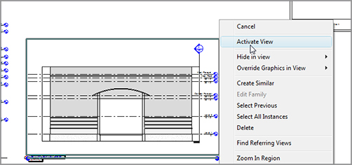
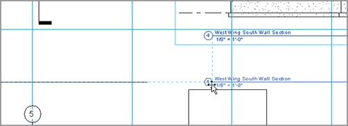
2. Zoom in on the viewport West Wing South Wall Section, as shown in Figure 14.11.
3. Select the view.
4. Right-click, and select Activate View (see Figure 14.11).
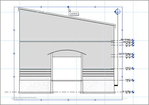
5. With the view activated, you can work on it just as if you had opened it from the Project Browser. Select the crop region, as shown in Figure 14.12.
FIGURE 14.12 Stretching the crop region so you can see the entire view
6. Stretch the top of the crop region up so you can see the entire view.
7. Stretch the bottom of the crop region down to expose the bottom of the section.
8. In the View Control toolbar, select Hide Crop Region.
9. Right-click, and select Deactivate View.
10. Right-click the view to the left of the West Wing South Wall Section (it’s the view called West Corridor Section), and select Activate View.
11. Stretch the crop region down so you can see the entire foundation.
12. Hide the crop region.
13. Right-click, and deactivate the view.
With the view widened, it’s coming close to the actual title. You can move the viewport and the title independently of one another. The following procedure involves moving the viewport up and then moving the view title down to provide some more room:
1. Select the West Wing South Wall Section viewport.
2. Hold down the pick button, and move the entire viewport up. As you do so, an alignment line appears. This means the views are physically aligned. When you see the alignment line, release the pick button.
3. Press Esc.
4. Select the view title, as shown in Figure 14.13.
5. Move it down. As you move the view title, it snaps in alignment to the view title to the left (see Figure 14.13).
FIGURE 14.13You can select the view title independently of the actual viewport.
Now that you have some experience creating sheets and making adjustments to the views and viewports, you can easily create one more sheet that contains sections.
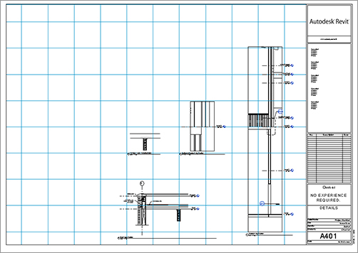
The following procedure focuses on creating a detail sheet. If you feel as though you can create this sheet on your own, go ahead. The sheet will be number A401, it will be named DETAILS, and the views to be added are Corridor Entry Section, Callout of Corridor Entry Section, Roof Taper Section, and TYPICAL WALL TERMINATION. Your finished sheet should look like Figure 14.14.
If you’d rather have some assistance, follow along with this procedure:
1. In the Sheets category in the Project Browser, right-click the Sheets title.
2. Select New Sheet.
3. Number it A401, and name it DETAILS.
4. In the Project Browser, drag the Sections (Wall Section) item Corridor Entry Section and place it in the sheet all the way to the right.
5. In the Project Browser, drag the Sections (Building Section) item Callout Of Corridor Entry Section onto the sheet to the top left of the previous section (see Figure 14.14).
6. Drag the section called Roof Taper Section to the bottom left of the first view you added.
7. Drag the view called TYPICAL WALL TERMINATION to the sheet directly to the left of Callout Of Corridor Entry Section (see Figure 14.14).
8. Zoom in on the view title for the Corridor Entry Section, as shown in Figure 14.15.
9. Select the Corridor Entry Section viewport. Notice the blue grips on the view title.
10. Extend the line by stretching the grip on the right to the right (see Figure 14.15).
11. Save the model.
FIGURE 14.15 Stretching the view title line to the right using the blue grip
Pan and zoom around to investigate all the reference markers. They’re starting to fill themselves out based on the sheets where you placed the referring views.
Now that you know how to manipulate a viewport, it’s time to look at the viewport’s properties. I think you’ll be glad to see how familiar these properties are.
Viewport Properties
Just like anything else in Revit, viewports have associated properties. You can just select the viewport and click the Properties button on the Ribbon if the Properties dialog isn’t already open.
The objective of the following procedure is to look through the viewport’s properties and to make some minor modifications. Follow along:
1. Open the view A401 – DETAILS (if it isn’t already open).
2. Select the Corridor Entry Section view (the tall section to the right of the sheet).
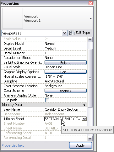
3. In the Properties dialog, scroll down the list until you arrive at Title On Sheet, as shown in Figure 14.16.
4. Change Title On Sheet to SECTION AT ENTRY CORRIDOR.
5. Click Edit Type.
6. In the Type Parameters, you can choose which view title you’ll be using, or whether you want any view title at all. For now, click OK.
7. Zoom in on the detail, and notice that the name has changed.
You’ve pretty much exhausted creating and manipulating sheets. It’s time to explore another sheet function: adding revisions.
FIGURE 14.16You can make the title on the sheet different from the view name.
An unfortunate reality in producing construction documents is that you must eventually make revisions. In CAD, you normally create a duplicate of the file, save that file into your project directory, and then create the revisions. The only way to keep track of them is to add a revision cloud and change the attribute information in the title block. In Revit, however, you’re given a revision schedule and the means to keep track of your revisions.
The objective of the next procedure is to add a revision cloud and to populate a schedule that is already built into the sheet. Follow these steps:
1. In the Project Browser, open Sheet A101.
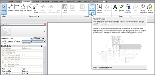
2. On the Annotate tab, click the Revision Cloud button, as shown in Figure 14.17. Notice that you’re now in Sketch Mode.
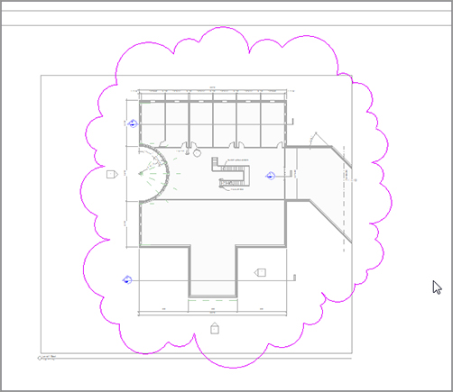
3. Place a revision cloud around the plan, as shown in Figure 14.18.
FIGURE 14.17The Revision Cloud button on the Annotate tab
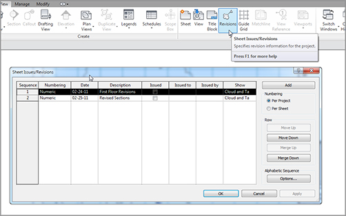
7. For Numbering, click the Per Project radio button.
8. Click OK.
9. In the Project Browser, open the sheet A301 – BUILDING SECTIONS.
10. On the Annotate tab, click the Revision Cloud button.
11. Place a cloud around the upper-right detail.
12. On the Mode panel, click Finish Edit Mode.
13. Select the cloud you just added.
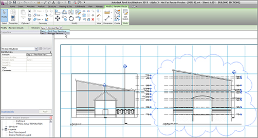
14. On the Options bar, make sure you have Seq. 2 – Revised Sections selected, as shown in Figure 14.21.
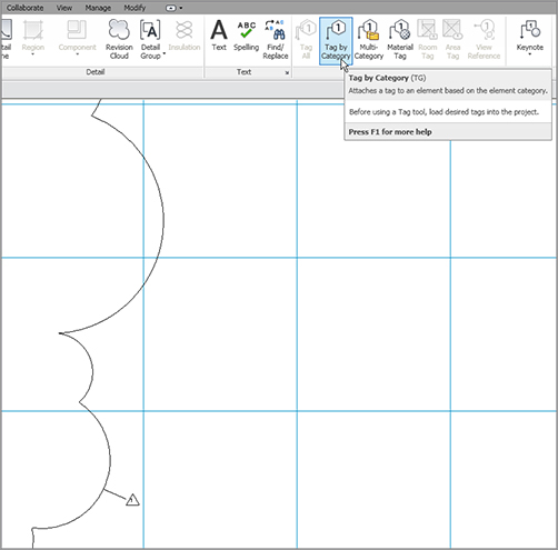
15. On the Annotate tab, select Tag By Category.
16. Place the revision tag on the cloud. You may also notice that the schedule in the title block is filled with only the appropriate revision relevant to this sheet.
FIGURE 14.21By selecting the revision cloud, you can specify the sequence from the Options bar.
Now that you have experience with the concept of how sheets and revisions come together, we need to explore one more avenue with populating sheet information. You may have noticed that the title blocks aren’t yet complete. The empty fields relate to project information that needs to be included on each sheet. This is where project parameters come in.
Because Revit is built upon a database, it makes sense that items like Project Name and Project Number are added to the design in a different manner than in CAD. In CAD, you fill out attributes sheet by sheet, or you externally reference a title block with the sheet information. In Revit, you fill out the project information in one place. The information you add to the database propagates down to the sheets. When, or if, this information changes, it’s done quickly and accurately.
The objective of the next procedure is to locate the project parameters and populate the model with the job information. Follow along:
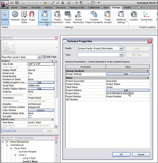
1. On the Manage tab, click Project Information, as shown in Figure 14.22.
2. In the Instance Properties dialog, click the Edit button next to Energy Settings, as shown to the right in Figure 14.22. The resulting dialog allows you to add the project’s geographical information as well as energy data. This lets you export the information to GBXML as well as provide information so your architectural model can be imported into Revit MEP.
3. Click OK.
4. You can fill out the rest of the information as follows (see Figure 14.22):
Project Issue Date: 5/10/11
Project Status: 100%
Project Name: NO EXPERIENCE REQUIRED
Project Number: 20090342
5. Click OK.
6. Open any sheet, and examine the title block. All of the information should be filled out.
You can now populate the information in a sheet. Before we jump into printing, we need to cover one more item quickly: adding a drawing list.
It goes without saying that this ingenious method of creating and managing sheets wouldn’t be quite perfect unless you could generate a sheet list and put it on a cover sheet. Well, this is Revit. Of course you can do this! The best part is that you already have the experience necessary to carry out this procedure.
The objective here is to create a sheet list and add it to a cover sheet. Follow these steps:
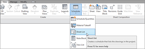
1. On the View tab, click Schedules Sheet List, as shown in Figure 14.23.
FIGURE 14.23Selecting Schedules Sheet List on the View tab
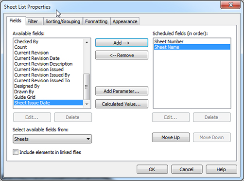
2. In the Sheet List Properties dialog, add Sheet Number and Sheet Name, as shown in Figure 14.24.
FIGURE 14.24 Adding Sheet Number and Sheet Name (in that order)
3. Click the Sorting/Grouping tab.
4. Sort by Sheet Number.
5. Select Ascending.
6. Click OK.
Wow! Creating a schedule is so easy, you’ll probably be doing this on your lunch break instead of playing Internet games.
While you’re still in the schedule, you can add a new row. This row will constitute a filler sheet that you can add to the Project Browser at a later date. To add a filler sheet, follow along:
1. Make sure you’re in the Sheet List schedule.
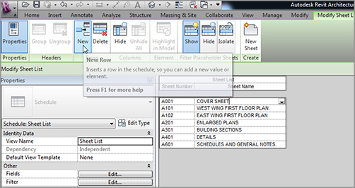
2. On the Rows panel, click the New button, as shown in Figure 14.25.
3. Call the new row COVER SHEET A001 (see Figure 14.25).
For now, let’s keep this schedule in the Project Browser and create a cover sheet that you can drag it onto. The objective of the next procedure is to create a new title-block family, add it to the project, and then drag the drawing list onto the cover. Follow these steps:
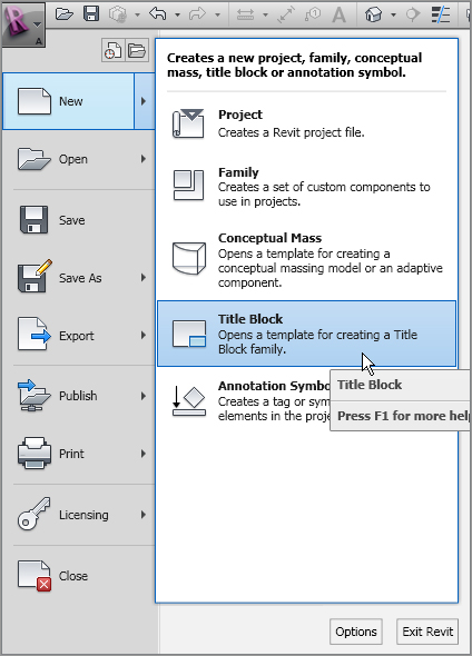
1. Click the Application button, and choose New Title Block, as shown in Figure 14.26.
2. Select E1 – 42 x 30.rft.
3. Click Open.
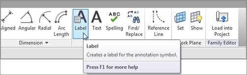
4. On the Text panel of the Home tab, click Label, as shown in Figure 14.27.
12. On the Format panel, click the Center Middle button.
13. Pick a point in the upper center of the sheet.
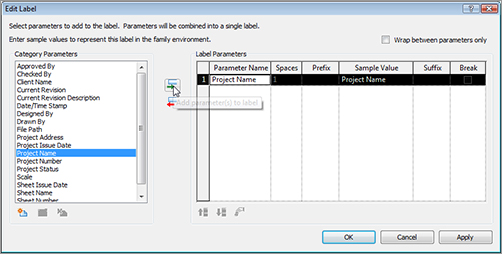
After you place the tag, you immediately see the Edit Label dialog. This dialog lets you add the label you wish. When you load this cover sheet into the project and add it to a new sheet, the project information will populate automatically.
The objective of the next procedure is to add the correct tags to the sheet. Follow along:
1. Select Project Name, and click the Add Parameter(s) to Label button, as shown in Figure 14.28.
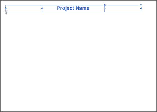
3. Click the label, and widen the grips. You may have to adjust the label so it’s centered in the sheet, as shown in Figure 14.29.
FIGURE 14.29 Adjusting the label so it’s centered in the sheet
4. Click the Application button, and then click Save As Family.
5. Save the file somewhere that makes sense to you. Call it Title Sheet.
6. Click Load Into Project.
If you have more than one project open, you’ll see a dialog in which you can choose which project to load the sheet into. If this is the case, choose the No Experience Required project you’re working on. If the sheet appears under your cursor in a sheet view, press Esc.
7. In the Project Browser, right-click Sheets, and select New Sheet.
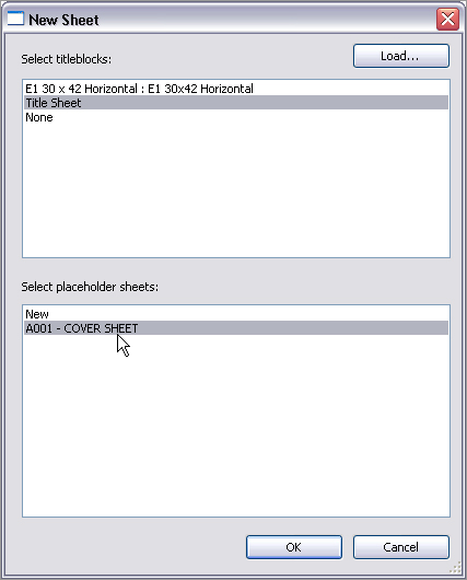
8. In the New Sheet dialog, select Title Sheet.
9. Also in the New Sheet dialog, you see the placeholder sheet you added to the schedule. Select it, as shown in Figure 14.30.
10. Click OK. Your tag is populated with the project information.
11. In the Project Browser, find Sheet List (it’s in the Schedules/Quantities category), and drag it onto the sheet.
12. Select the schedule, and adjust it so the text is readable. Your title sheet, although not very glorious, should look like Figure 14.31.
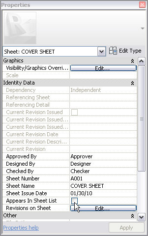
In most cases, you don’t want the actual cover sheet to be an item in the schedule. You can fix this. While still in the cover sheet, deselect Appears In Sheet List in the Properties dialog, as shown in Figure 14.32.
FIGURE 14.32 Deselect the Appears In Sheet List option.
Perfect! You have a handful of sheets. The beauty is that you don’t have to leave the model to see how these sheets are shaping up. In Revit, they’re always just a click away.
You have these sheets, so let’s explore how you send them to the plotter. After all, it’s paper construction documents that you’re producing.
Luckily, printing is one of the easiest things you’ll be confronted with in Revit. However, you must consider some dangerous defaults when printing. I can go out on a limb and say that printing from Revit is too easy in some cases.
The objective of the next procedure is to print a set of drawings. Pay special attention to the warnings—they will steer you clear of danger. Follow along:
1. Click the Application button, and select Print.
2. For the printer name, select the printer you wish to print to.
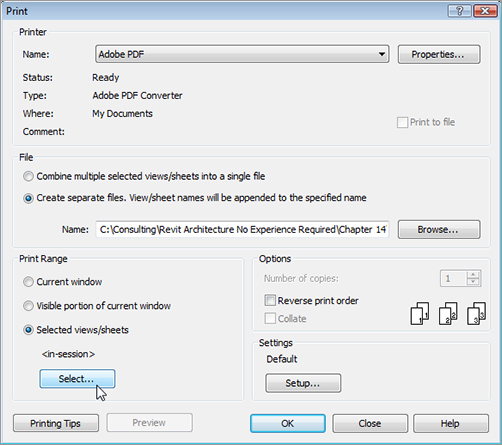
3. If you’re printing to a file, you can choose to combine all files into one or create separate files. Choose to combine into one file. If you aren’t printing to a file, ignore this choice.
4. For Print Range, you can print the current window or the visible portion of the current window, or you can choose Selected Views/Sheets. In this case, choose Selected Views/Sheets.
5. Click the Select button, as shown at lower left in Figure 14.33.
6. At the bottom of the View/Sheet Set dialog, deselect Views.
FIGURE 14.33 Choosing the options to print the drawings
7.Only the sheets are listed. Click all the sheets.
8. Click OK.
9. Revit asks if you want to save the settings for a future print. Click No.
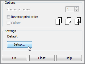
10. In the lower-right corner, in the Settings area, click the Setup button, as shown in Figure 14.34.
11. For Paper, choose the correct paper size you wish to print to.
12. For Paper Placement, choose Center.
13. For Zoom, select Zoom: 100% Of Size.
14. For the options, select Hide Ref/Work Planes.
15. Select Hide Unreferenced View Tags.
16.Hide Scope Boxes.
17. Hide Crop Boundaries.
18. Click OK.
19. Click OK again, and your plot is off.
20. Save the file.
There you have it.
The book doesn’t create a sheet for every single view. If you feel as though you’re still lacking experience regarding creating sheets and printing, go ahead and create more sheets, and keep printing away until you feel confident to move on to Chapter 15, “Creating Rooms and Area Plans.”