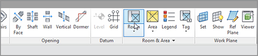
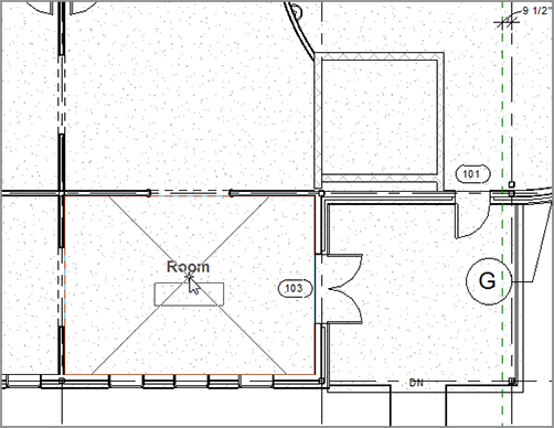
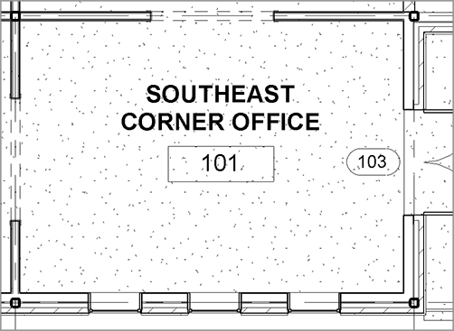
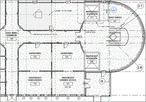
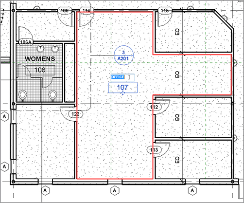
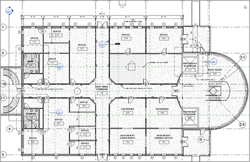
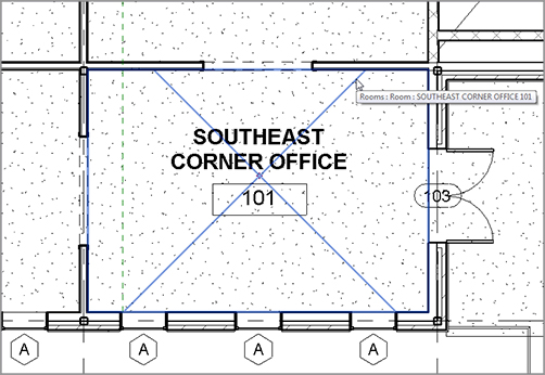
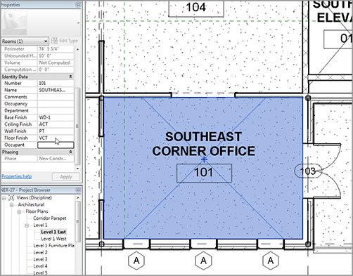
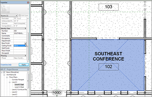
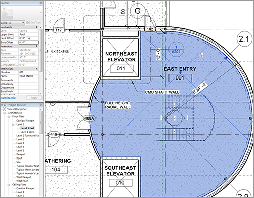
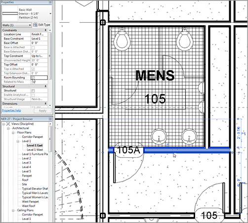
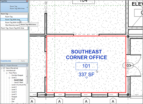
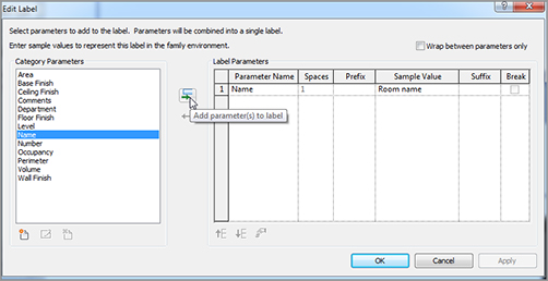
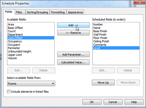
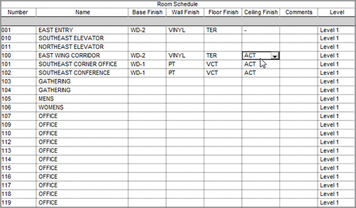
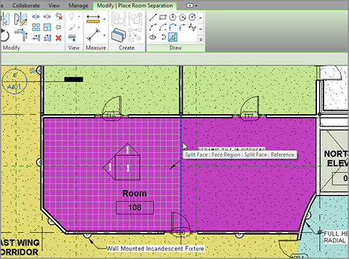
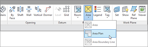
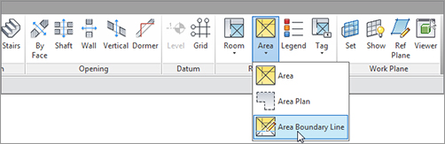
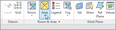
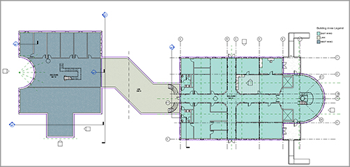
This chapter brings you to a great point in Revit. You’re in a position where you can begin to build on what you’ve added to your model up to this point. By creating rooms and areas, you’re starting to merge the model with the database. In Chapter 11, “Schedules and Tags,” you did the same thing; but by adding rooms and areas, you physically build your construction documents while at the same time adding crucial information to the model’s database. In this chapter, here is what we are going to learn: The first topic we’ll tackle is the task of creating a room and adding it to the model. The procedures that follow will focus on finding where to launch the room and areas, and the parameters Revit looks for while placing a room into the floor plan. Because Revit draws from a database to gather information, the process of creating a room boils down to you adding some notes to an already-built form. When you place the room in the model, Revit automatically tags it. Unlike other drafting applications, however, Revit doesn’t rely on the tag for its information. When a room is in the model, it can either contain or not contain a tag. This is a great way to organize the flow of room information. To get started, open the model you’ve been working on. If you missed the previous chapter, go to the book’s web page at The objective of the following procedure is to find the Room & Area panel on the Home tab, and to configure and add some rooms to the model. Follow along: FIGURE 15.1 Clicking the Room button on the Room & Area panel of the Home tab FIGURE 15.2 When you hover your mouse over the intended area of the room, you see an indication that Revit has found the bounding edges. You’ve now added a room to the model. Of course, it’s a nondescript room name with a nondescript room number. The following procedure will correct that. The objective here is to change the room name and number on the screen: Now that you have a room in place and it’s named properly, you can start cooking in terms of adding more rooms. This is because Revit will begin to sequentially number the rooms as you place them into the model. FIGURE 15.3 Changing the room name and number to SOUTHEAST CORNER OFFICE and 101, respectively The objective of the next procedure is to populate the rest of the east wing with rooms. Follow these steps: FIGURE 15.4 The first floor layout up to this point I think you’re getting the concept of adding rooms. Although you’ve added a number of rooms to the east wing, you need to begin adding some plain old offices. The next procedure will involve adding offices to the rest of the spaces in the east wing of Level 1. From there, you can look at a room’s properties and figure out how to alter the room information. Follow along: FIGURE 15.5 Renaming the office FIGURE 15.6 Adding rooms to the remainder of the spaces With all the rooms in (at least in this section of the building), you can begin examining specific properties to see how you can add functionality and further populate the database information pertaining to each room. Each room has specific properties associated with it. There are floor finishes and wall finishes as well as ceiling types and finishes. It would be nice if Revit picked up this information by “reading” the ceilings, walls, and floors, but it doesn’t. And for good reason—imagine having to create a different wall type for each paint color, and then splitting each partition as it passed through each room. In Revit, you specify individual room finishes in the properties of the room itself. The objective of the next procedure is to generate additional room information in the properties of the room. Follow these steps: FIGURE 15.7 Hover the cursor over the room until the X appears. FIGURE 15.8 Adding values to the identity data Changing a room’s properties is a simple task. There is, however, one more item to discuss. It pertains to a room that spans multiple floors, such as the east entry. FIGURE 15.9 When a field has been added to the database, it’s available for the rest of the rooms. The objective of the next procedure is to change the height of the east entry room’s properties: FIGURE 15.10 Selecting the east entry room Now that you have experience changing the properties of the rooms, it’s time to look at the properties of the walls that divide the rooms. Certainly you noticed that when you placed the rooms in the lavatories, the rooms didn’t fill the small entry areas. You can correct this by changing the walls’ room-bounding properties. By default, each wall you add to the Revit model automatically defines a room boundary, and this is what you want 95 percent of the time. In some situations, however, you don’t want a wall to separate the room. In such cases, you can modify the instance parameters of the wall to disallow the division of the room. The objective of the following procedure is to turn off the room bounding in certain walls. Follow along: Having the ability to easily add rooms and manipulate the information in the Revit database gives you a tremendous advantage as you move forward with the rest of the model. Also, that information is relayed into the room’s tag, which is automatically added as you place rooms into the model. This concept brings us to the next topic: how to change the tag to display the information you desire on the drawings. As mentioned earlier, the room tag is merely a vehicle to relay the room’s data to the construction documents. As a default, a room tag is added automatically as you place the room into the model. A default room tag is included, but you aren’t stuck with it. FIGURE 15.11 Selecting the partition within the Men’s lavatory The objective of the next procedure is to add an alternate room tag to the room, and to open the tag’s family editor to investigate the composition of the tag. Follow these steps: That was way too easy! Let’s take a closer look at what you just did. A room tag is nothing more than the cover sheet you created back in Chapter 14, “Creating Sheets and Printing.” All you need to do is open the file and place a tag into the family. FIGURE 15.12 Change the type to Room Tag With Area. To open the tag’s Family Editor, follow this procedure: FIGURE 15.13 A list of available parameters you can add to the room tag Now that you know what tag Revit uses when it places a room and how to manipulate that tag, let’s tie the tag into something more robust. A tag is just a reflection of the room data. You can add another Revit object that does the same thing: a room schedule. Up to this point in your career you’ve been adding room information twice, or sometimes three times. Why? Because you had to fill out the tag in the plan and then fill out the same information in the room schedule. If you were in the unfortunate situation of having an enlarged plan, then you added the information a third time. When you needed to change that information, you had to do so in multiple places. I’m not saying that Revit will end all your problems, but it sure will make life easier. The objective of the next procedure is to create a room schedule. You’ll then finish filling out the room information from the schedule, thus saving time and increasing accuracy. Follow along: FIGURE 15.14 Adding fields to the schedule FIGURE 15.15 The room schedule FIGURE 15.16 Filling out the room schedule With the rooms in place and a schedule filled out, it’s time to move to a more colorful aspect of placing rooms in the model: adding a color-fill plan. Another benefit of using the room feature in Revit is that you can add a color-fill plan at any time, and you can create virtually any type of color scheme or pattern scheme you desire. And here’s the best part: adding one is so easy, it’s almost fun. The objective of the next procedure is to make a duplicate of the East Wing floor plan and create a color scheme based on room names. Follow these steps: FIGURE 15.17 Duplicating the view FIGURE 15.18 Clicking the Legend button FIGURE 15.19 Specifying the color scheme FIGURE 15.20 Proceeding to edit the scheme Pretty cool concept! You may notice that the two rooms you skipped are still white. It’s time to look at the situation you have here. The problem is, there are no walls dividing the two rooms; but it would be nice to have two separate rooms anyway. To do this, you can add a room separator. Although it seems like a small issue, adding room separators has been known to confuse people. In Revit, you can physically draw a room without any walls. Or you can draw a line in the sand between two rooms that aren’t separated by an actual wall. This is known as adding a room separator. The objective of the next procedure is to separate the kitchen from the break room by adding a room separator. Follow along: FIGURE 15.21 Place a room over the tiles (it will spill into the adjacent room). FIGURE 15.22 Click the Room Separation Line button on the Room & Area panel of the Home tab. FIGURE 15.23 Adding the room separation line You’re really moving along. You now have a fully coordinated room schedule tied into a room color-fill plan that can be modified by simply changing a room tag. How did you ever live without Revit? The next item to discuss is how to create a gross area plan. The process is similar but slightly more involved than creating a room color plan. Almost any job of considerable size will require an area plan at some point in the project’s early development. This normally occurs in the programming phase, but the need for this type of plan can persist well into the later stages of the project. The objective of the next procedure is to create a separate floor plan and then divide it into areas. Follow these steps: FIGURE 15.24 Clicking the Area Plan button FIGURE 15.25 Choosing the Area Boundary Line FIGURE 15.26 Separating the areas FIGURE 15.27 The Area button FIGURE 15.28 The plan is divided into three areas. FIGURE 15.29 Adding an area legend Great job! You now have experience with creating area plans. If you feel as though you could use some more practice before you begin a real project, there are five more floors in this model that you can work on. You can either work on your own or step back through this chapter’s procedures.
CHAPTER 15
Creating Rooms and Area Plans
Creating Rooms
www.sybex.com/go/revit2012ner. From there, you can browse to Chapter 15 and find the file called NER-26.rvt.
Configuring Properties
Room-Bounding Properties
Placing and Manipulating Room Tags
Adding a Room Schedule

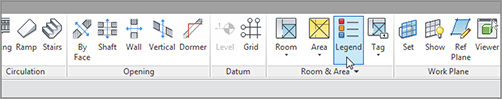
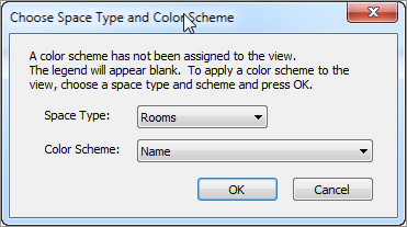
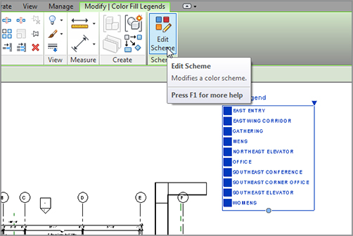
Adding a Color-Fill Plan
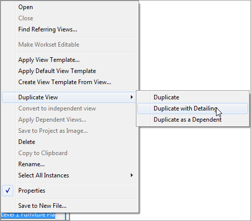
![]() Duplicate With Detailing, as shown in Figure 15.17. If you get an error pertaining to the view references, click the Delete button.
Duplicate With Detailing, as shown in Figure 15.17. If you get an error pertaining to the view references, click the Delete button.
Adding Room Separators
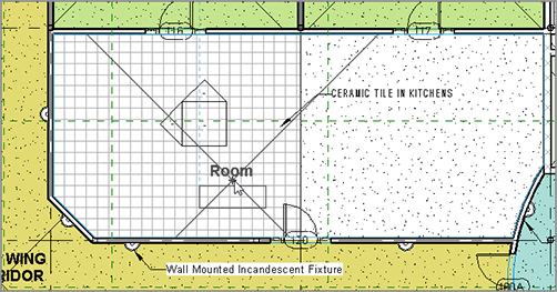
![]() Room Separation Line, as shown in Figure 15.22.
Room Separation Line, as shown in Figure 15.22. 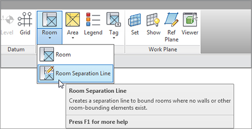
Creating an Area Plan
![]()
Area Tag.rfa. 
Are You Experienced?
Now you can…