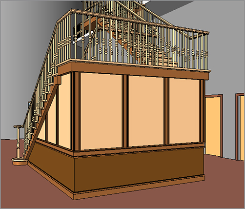
More on walls? Really? It seems as though all we do is walls. Well, that’s because buildings are composed mainly of walls. As you may have noticed, the exterior walls are compound wall structures with reveals and parapet caps. In the west wing, you have a staircase that is completely unsupported. It would be nice to add a wall to make those stairs less spongy. Given the fact that the west wing is a high-end architectural woodwork area, that wall could use some trims that can be added right to the wall’s profile. Also, we haven’t touched on a curtain wall of any kind.Here is what you are going to learn in this chapter:
The first item to tackle is how to develop a wall with different materials. The exterior walls you’ve been using in this model are a prime example of compound walls. The bottom 3´ (900mm) of the wall consists of concrete block, and the rest of the wall is brick. When you cut a section through the wall, you can see that the wall has an airspace as well as a metal stud-wall backup.
Usually, these chapters start with a claim that “the following procedure is so easy a caveman could do it” (or something of that nature). The development of compound walls isn’t the easiest thing you’ll tackle in Revit. This procedure is somewhat touchy, and doing it well takes practice. In this section, you’ll create an interior wall with a wood finish on the bottom along with different wood material on the top. You’ll also extrude a chair rail along the wall.
To get started, open the model you’ve been working on. If you missed the previous chapter, go to the book’s web page at www.sybex.com/go/revit2012ner. From there, you can browse to Chapter 16 and find the file called NER-27.rvt.
The objective of the next procedure is to create a compound wall from a basic wall. Follow along:
1. Open the Level 1 West dependent floor plan view.
2. On the Home tab, click the Wall button.
3. In the Type Selector in the Properties dialog, choose Basic Wall : Generic – 6˝ (152mm).
4. In the Properties dialog, click the Edit Type button.
5. Click Duplicate.
6. Call the new wall Stairwell 3 support wall, and click OK.
7. Click the Edit button in the Structure row.
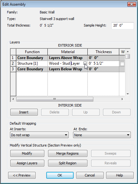
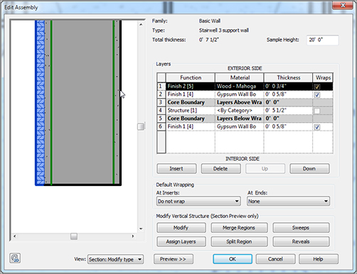
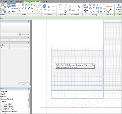
8. Click into the Material cell for the Structure row, as shown in Figure 16.1.
9. Click the […] button.
10. In the Materials dialog, select Wood – Stud Layer, and click OK.
11. Change the thickness to 5 1/2˝(140mm) (see Figure 16.1).
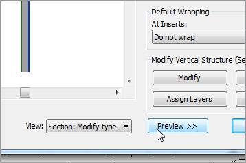
12. At the bottom of the Edit Assembly dialog is a Preview button. Click it (see Figure 16.2).
13. With the preview open, change View to Section: Modify Type Attributes.
FIGURE 16.1Changing the structure to a 5 1/2˝ (140mm) wood stud
It doesn’t seem as though you’ve done much, but you’ve set the stage to start building your wall. It’s time now to focus back on the Layers field.
Adding Layers to the Compound Wall
If you’re an AutoCAD veteran, the term layer takes on a different meaning. In Revit, the term layer, as it pertains to a wall assembly, represents a material layer that is assigned an actual thickness as well as its own material.
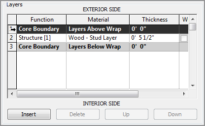
As you can see in Figure 16.3, Revit understands the difference between interior and interior. For the following procedure, you’ll add materials to both the exterior and interior portion of the wall. Follow these steps:
1. In the Layers area, click the number 1, as shown in Figure 16.3 (it’s the row that holds the Layers Above Wrap field).
FIGURE 16.3 Clicking row 1 to highlight the entire row
2. Click the Insert button. Revit creates a new layer above the one you select; the new layer is always set to Function: Structure [1], Material: <By Category> and Thickness:0.
3. Change Function to Finish 1 [4].
4. Click into the Material cell, and click the […] button.
5. Select Gypsum Wall Board.
6. Click OK in the Materials dialog.
7. Change Thickness to 5/8˝ (16mm).
8. Click row 4 (Layers Below Wrap).
9. Click the Insert button.
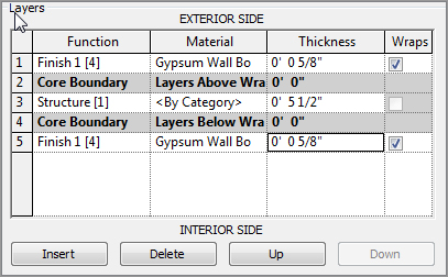
10. Click the Down button, as shown at lower right in Figure 16.4. It’s located below the Layers area. Your new layer becomes 5.
11. Change Function to Finish 1 [4].
12.Click into the Material cell, and click the […] button.
13. Find Gypsum Wall Board.
14. Click OK in the Materials dialog.
15. Change Thickness to 5/8˝ (16mm). Your Layers field should resemble Figure 16.4.
FIGURE 16.4 Adding a 5/8˝ gypsum layer to the interior side of the wall
Now that the wall is wrapped with one layer of 5/8˝ (16mm) gypsum on each side, it’s time to start placing the veneered plywood layers on the exterior of the wall.
The objective of the next procedure is to add a 3/4˝ (19mm) plywood layer to the exterior of the wall. Follow along:
1. Click 1 Finish 1 [4] (the top layer).
2. Click Insert.
3. Change Function to Finish 2 [5].
4. Change Material to Wood – Mahogany (it’s the mahogany material that has Plywood for the cut pattern). Click OK.
5. Change the Thickness to 3/4˝ (19mm). Your wall’s layers should resemble Figure 16.5.
6. At the bottom of the dialog, click the OK button.
7. Click Apply.
FIGURE 16.5Adding the 3/4˝ (19mm) mahogany veneered plywood material
Next, let’s go back in and split the wall materials in two. It would be nice if you could have cherry at the top and mahogany at the bottom. Revit gives you the ability to do this.
Adding New Materials by Splitting a Region
If you want more than one material along the face of a wall, you can use the Split Region command in the Edit Assembly dialog. The objective of the following procedure is to add a new material and then apply it to the top half of the plywood face. Follow these steps:
1. Click the Edit button in the Structure row.
2. Click Layer 1 (the top layer).
3. Click Insert.
4. Change Function to Finish 2 [5].
5. For Material, select Wood – Cherry, and click OK. (Don’t give it a thickness. The next procedure takes care of that.)
6.Click the Split Region button, as shown in Figure 16.6.
7. Move your cursor up the plywood face. Notice that the cursor turns into a knife. You also see a short, horizontal line within the plywood: this indicates where the region will be cut.
8. When you see 3´–0˝ (900mm) in the temporary dimension, pick the point as shown in Figure 16.6. Do not press Esc when you’re finished! If you place the split in the wrong place, click the Modify button, and then select the split line you just created. You can then click the dimension field to edit the location. There is also a direction arrow that specifies whether the split is set from the bottom up (what you just did) or from the bottom down.
FIGURE 16.6 Cutting the plywood at a specific height
You’ve split the plywood. The only thing left to do is to apply a new material to the upper region. You can accomplish this by using the Assign Layers button.
Assigning Material to Different Layers
The Assign Layers command lets you choose where you would like to assign a layer. This is useful in the context of this dialog because you aren’t stuck without the ability to move the layers around the wall as necessary. Of course, when you split the wall as you just did, notice that the thicknesses of the two wood layers are set to 0 and Variable. Revit needs you to assign an alternate layer at this point.
The objective of the following procedure is to assign the cherry layer to the upper portion of the plywood. Follow along:
1. Pick the Layer 1 row (Wood – Cherry), as shown in Figure 16.7.
FIGURE 16.7 Assigning the cherry layer to the upper portion of the wall
2. Click the Assign Layers button (see Figure 16.7).
3. Move your cursor over the upper region of the plywood layer, and pick. Cherry is assigned to the upper portion of the wall, and the thicknesses are set to 3/4˝ (19mm) (see Figure 16.7).
4. At the bottom of the dialog, click OK.
5. Click Apply.
6.Click the Edit button in the Structure row to get back to the Edit Assembly dialog.
7. Pan to the top of the wall in the display, as shown in Figure 16.8.
FIGURE 16.8 Unlocking the plywood to enable independent movement after the wall is placed into the model
12. Click OK.
13. Click OK one more time to get to the model.
14. Click the Modify button on the Home panel.
15. Save the model.
By unlocking the layer, you can move that layer up or down depending on what you need. Another good example of the usefulness of this functionality is when you need to slide a brick ledge down past a foundation.
Some people find splitting the regions in the Edit Assembly easy, while others find it to be more difficult. I found the procedure difficult at first. If you’re like me, this technique will require practice until you’ve done a few more walls. Don’t worry—it gets easier as time passes.
Adding an automatic sweep along this wall would be nice. Come to think of it, a wood base and a chair rail would finish off this wall perfectly.
The concept of adding a wall sweep is as close to actual construction as you can come without setting up a chop saw. That is because when you want to add a specific profile to sweep along a wall, you need to go outside the model, find (or create) the profile, and then bring it into the model. This process is similar to ordering trim and installing it.
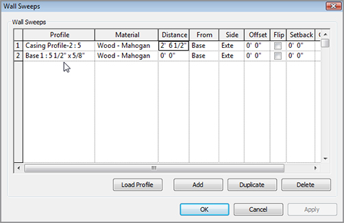
The objective of the following procedure is to load a base and a chair rail trim into the model. You’ll then include these items in the wall you’ve been working on. Follow along:
1. On the Insert tab, click the Load Family button.
2. Go to the Profiles directory.
3. Load the files Base 1.rfa and Casing Profile-2.rfa. (Use Ctrl to select both files.)
4. On the Manage tab, click the Materials button.
5. Select the material Wood – Cherry.
6. Click the Duplicate button at the bottom of the dialog.
7. Call the new material Wood – Cherry – Solid.
8. Change the cut pattern to Wood 1.
9. Select the material Wood – Mahogany.
10. Click the Duplicate button.
11. Change the name to Wood – Mahogany – Solid.
12. Change the cut pattern to Wood 1.
13. Click OK.
14. On the Home tab, click the Wall button.
15. Make sure the current wall is Stairwell 3 Support Wall.
16.In the Properties dialog, click Edit Type.
17. Click the Edit button in the Structure row.
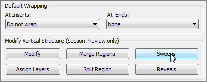
18. Click the Sweeps button, as shown in Figure 16.9.
26.Click OK, and zoom in on the wall where the sweeps are, so you can confirm they’re placed as expected.
27. Click OK again.
28. Click OK one more time to get back to the model.
29. In the Properties panel, make sure Base Offset is set to 0´–0˝.
30. In the Options bar, set Height to Unconnected with a height of 10´–0˝(3000mm)
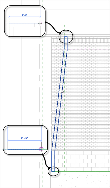
31. Set Location Line to Finish Face: Exterior.
32. Set Offset to -1˝ (-25mm).
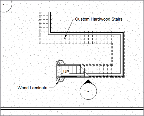
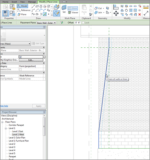
33. Draw the wall by snapping to the inside of the stringers, as shown in Figure 16.11. You want to go in a clockwise direction, so start with the northern part of the staircase, as illustrated by the 1 in Figure 16.11.
FIGURE 16.11 Placing the wall clockwise in the model
34. On the Geometry panel on the Modify | Place Wall tab, click the Wall Joins button.
35.Using the Wall Joins tool, go to each wall corner and make the join Mitered.
The wall has been added to the model. Because you’re placing it underneath a staircase, there will be issues with the wall’s profile. This brings us to the next section of this chapter, which guides you through modifying a wall’s shape after it has been placed into the model.
Modifying a Wall’s Profile in Place
Although we touched on modifying a wall profile back in Chapter 2, “Creating a Model,” in this section we’ll take this technique to the next level. You can make a wall conform to any odd geometric shape you wish if you follow a few simple rules and procedures.
The objective of the following procedure is to edit the profile of the new walls to conform to the profile of the stairs. Follow these steps:
1. On the View tab, click the Elevation button.
2. Place an interior elevation, as shown in Figure 16.12.
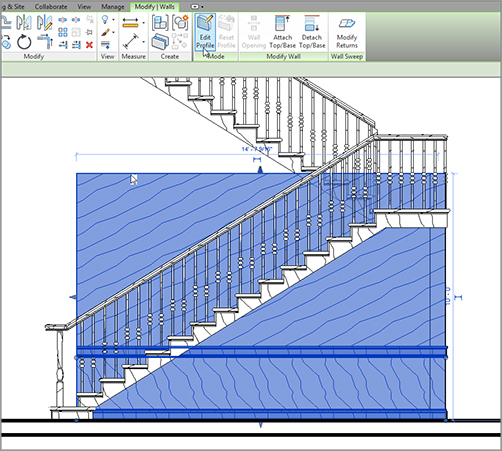
5. On the Mode tab, click Edit Profile (see Figure 16.13).
FIGURE 16.13 Selecting the wall to be modified, and clicking the Edit Profile button
6. On the Draw panel, click the Pick Lines icon.
7. Pick the underside of the stairs. Follow the profile exactly.
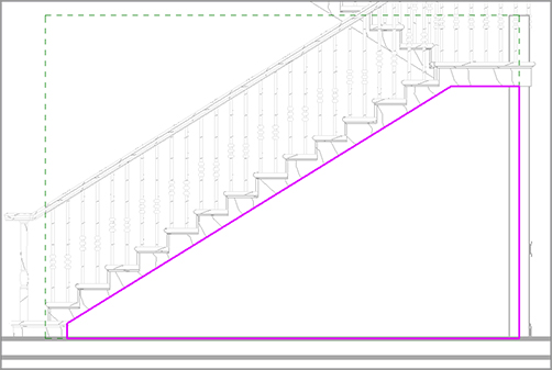
8. Delete the existing top magenta line and the existing left magenta line by selecting them and pressing the Delete key. All you should have left is the profile shown in Figure 16.14.
9. Use the Trim/Extend Single Element command to clean up all the corners. Revit won’t allow you to continue if you don’t (see Figure 16.14).
10. Click Finish Edit Mode. Your wall is trimmed to the underside of the stairs.
FIGURE 16.14Cleaning up the lines so they form a continuous loop
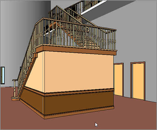
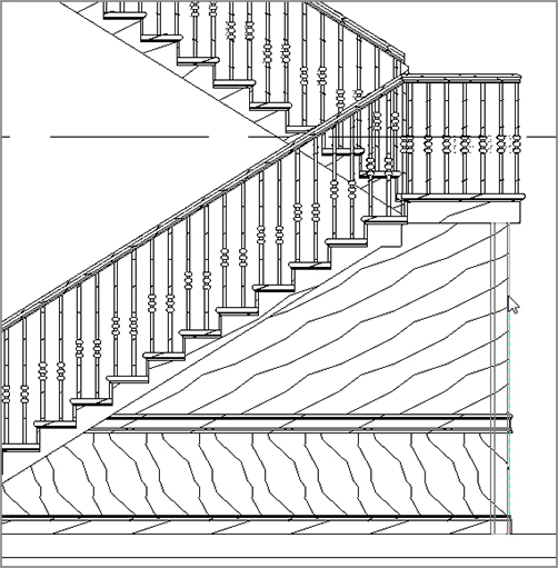
11. Repeat the procedure for each wall under the stairs. Remember to add elevations for each. Your finished walls should look like Figure 16.15.
FIGURE 16.15 The finished walls should follow the profile of the stairs.
Now that you can create a compound wall and modify it to fit in an odd place, it’s time to learn how to manually add some sweeps.
Manually Adding Host Sweeps
The problem with the wall scenario that you created in the previous procedure is that you have only horizontal wall sweeps. Suppose you need some vertical wall sweeps. This is where host sweeps come into play.
A host sweep is exactly like the sweeps you just added to the wall’s properties, but by adding a host sweep, you can add sweeps manually.
The objective of the next procedure is to configure and add a host sweep to the model. Follow along:
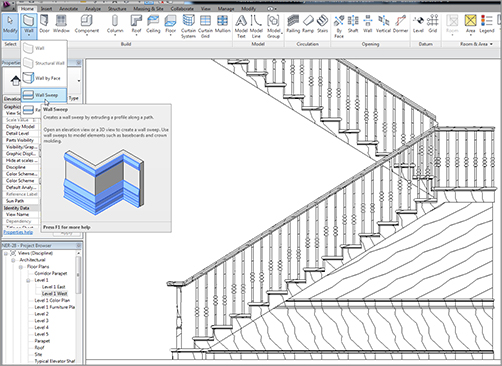
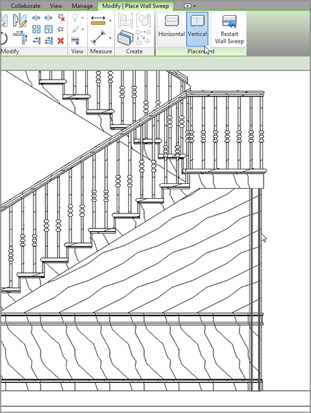
1. Go to the elevation shown in Figure 16.16 (the first one you placed, looking at the stairs).
2. On the Home tab, click the down arrow on the Wall button, and select Wall Sweep (see Figure 16.16).
13. Select the vertical trim. Notice the grips on the top and the bottom. Pick the bottom grip, and drag it up to meet the top chair rail, as shown in Figure 16.19.
14. Add another sweep about 3´–0˝ (900mm) to the left of the first sweep.
15. When the sweep is in, select it. A temporary dimension appears. Change the dimension to 3´–0˝ (900mm).
FIGURE 16.19Dragging the sweep up to the chair rail
16. Drag the bottom up.
17. Repeat the procedure so your elevation looks like Figure 16.20.
FIGURE 16.20 The finished south wall of the stairs
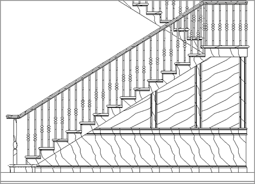
18.Add vertical rails at a 3´–0˝ +/– (900mm)to the other walls as well. Your walls should look like Figure 16.21.
FIGURE 16.21 The final walls with the sweeps added
So, you can now make modifications to a simple wall in any direction. You have experience adding sweeps to the wall’s composition, and you can add sweeps freehand when you need to.
One other type of wall that we should cover before we get to curtain walls is a stacked wall. When you need a compound wall, the outside face must always be in alignment. When you run into this situation, you have to construct an entirely new wall.
A stacked wall, simply put, is a wall created by stacking two premade walls together. You can’t have a stacked wall without at least two basic walls that you can join together. The good thing about stacked walls is that you can stack as many as you like. I recommend that you use some restraint, though—these walls can start to use up memory if you get too carried away.
The objective of the following procedure is to join three basic walls together to create one stacked wall. The result will create an alcove for architectural casework. Follow these steps:
1. Go to Level 1, and on the Home tab, click the Wall button.
2. In the Type Selector menu in the Properties dialog, select Basic Wall : Interior 6 1/8˝ (156mm) Partition (2Hr).
3. Click Edit Type.
4. Click Duplicate.
5. Call the wall 18˝ (450mm) Soffit Wall, and click OK.
6. Change Wrapping At Inserts and Wrapping At Ends to Interior.
7. Click the Edit button in the Structure row.
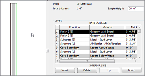
8. In the Layers area, click 3 Core Boundary (Layers Above Wrap), and click Insert.
9. Set Function to Structure [1].
10. Set Material to Air Barrier – Air Infiltration Barrier.
11. Set Thickness to 8 1/4˝ (210mm).
12. Click Insert (to insert another layer above).
13. Set Function to Substrate [2].
14. Set Material to Metal – Stud Layer.
15. Set Thickness to 3 5/8˝ (92mm) (see Figure 16.22).
16. Click OK twice.
17. To the left of the Ribbon, click the Modify button (doing so clears the Wall command).
It’s time to begin building the stacked wall. Because you have two walls to work with, you can specify them in the Edit Assembly dialog for the stacked wall.
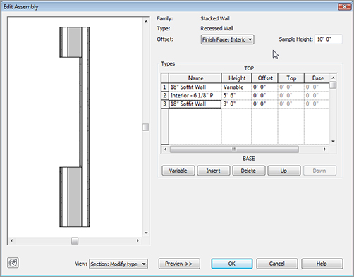
The objective of the next procedure is to join the 18˝ soffit wall with the 6 1/8˝(156mm) partition wall. Follow along:
1. On the Home tab, click the Wall button if it isn’t already running.
2. Scroll down the Type Selector until you arrive at Stacked Wall: Exterior – Brick Over CMU w Metal Stud, and select it.
3. Click Edit Type.
4. Click Duplicate.
5. Call the new wall Recessed Wall, and click OK.
6. Click Edit in the Structure row.
7. For Offset, select Finish Face: Interior.
8. In the Types area, change Wall 1 to 18˝ (450mm) Soffit Wall.
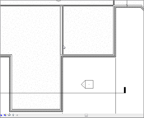
16. Draw the wall in the west wing, as shown in Figure 16.24. (If you wish, you can create an elevation, or cut a section through the wall.)
FIGURE 16.24 Adding the new stacked wall to the model
With the concept of stacked walls behind us, we can move into the crazy world of curtain walls. Although curtain walls are complex in nature, Revit handles them quite well.
The topic of curtain walls brings us away from the conventional mindset of walls. Curtain walls are placed into the model the same way as conventional walls, but curtain walls have many more restrictions and Element Properties that we should examine before you go throwing one into your model.
With that said, curtain walls also provide the most dramatic effect on your building. As this section will explain in detail, a curtain wall is composed not only of glass and aluminum extrusions; it can be constructed from building materials such as brick, CMU, and wood. You can also predefine the materials and the spacing, or you can create them grid by grid, depending on your situation.
The first part of this section will focus on adding a predefined curtain system to the model.
Adding a Predefined Curtain Wall
The quickest way to model a curtain wall is to use one that has already been created for you. The out-of-the-box curtain walls that are provided with Revit have enough instance and type parameters available to make the curtain wall conform to your needs for each situation.
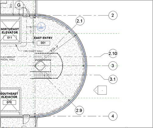
The objective of the next procedure is to add a predefined curtain wall system to the radial east entry wall. Follow these steps:
1. In the Project Browser, open the Level 1 East dependent view.
2. Zoom in on the east entry.
3. On the Home tab, click the Wall button.
4. In the Type Selector, select Curtain Wall: Storefront.
5. Click Edit Type.
6. Click Duplicate.
7. Call the new curtain wall East Entry, and click OK.
8. Notice that you can configure many parameters. Verify that Automatically Embed is selected. For Vertical Grid Pattern, change Spacing to 4´–0˝ (1220mm).
9.Select Adjust For Mullion Size.
10. For Horizontal Grid Pattern, change Layout to Maximum Spacing, and change the spacing to 4´–0˝ (1220mm). Also select Adjust For Mullion Size.
11. Click OK.
12. In the Instance Properties dialog, change Base Offset to 3´–7˝ (1100mm).
13. Set Top Constraint to Up To Level: Roof.
14. Set Top Offset to -1´–0˝ (-300)(that’s minus 1´–0˝ 300).
15. On the Draw panel, click the Pick Lines icon.
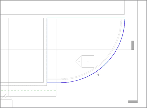
16. Pick the radial entry wall, as shown in Figure 16.25. Make sure you’re picking the wall centerline.
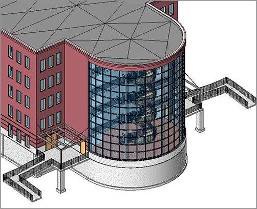
17. Go to a 3D view. Your curtain wall should resemble Figure 16.26.
FIGURE 16.25 Picking the radial entry wall to add the curtain wall
The ability to create an automatic curtain wall such as the radial one in the west entry way is quite an advantage when it comes to quickly modeling a curtain system. However, you won’t always be presented with a perfectly square vertical shape. This is where creating a blank curtain wall comes in handy. You can then add grids and mullions at spaces that are at odd intervals.
Adding a Blank Curtain Wall
A blank curtain wall is nothing but a giant chunk of glass. By adding a blank curtain wall, you tell Revit, “Don’t bother spacing the panels—I’ll do it myself.”
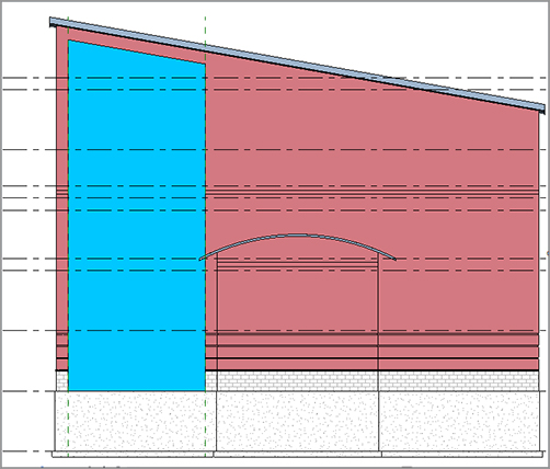
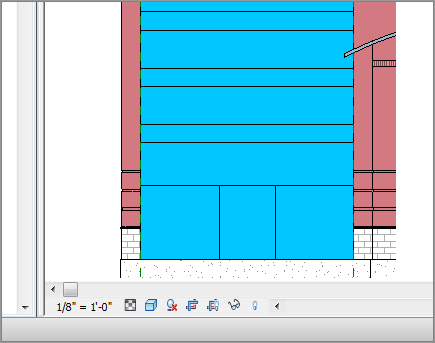
The objective of the next procedure is to create a blank curtain wall and add it to the model. You’ll then go to an elevation and edit the profile of the panel. Follow along:
1. In the Project Browser, open the Level 1 West dependent view.
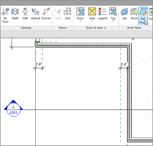
2. On the Work Plane panel of the Home tab, click Ref Plane, and then click Pick Lines on the Draw panel.
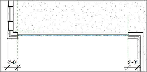
3. Offset a reference plane 2´–0˝ (600mm) from the face of brick, as shown in Figure 16.27.
FIGURE 16.27 Offsetting two reference planes 2´–0˝ (600mm) from the face of brick
4. On the Home tab, click the Wall button.
5. In the Type Selector, pick Curtain Wall: Curtain Wall 1 from the list.
6. Click Edit Type.
7.Click Duplicate.
8. Call the new curtain system South West Entry, and click OK.
9. Select the Automatically Embed check box.
10. Click OK.
11. For the Base Offset, change the value to 0´–0˝.
12. For Top Constraint, set the value to Up To Level: Level 5.
13. For Top Offset, change the value to 0´–0˝.
14. Draw the wall at the centerline of the wall between each reference plane, as shown in Figure 16.28. Note that if you draw from left to right, the exterior face of the new wall will be to the inside.
FIGURE 16.28 Drawing the curtain wall at the centerline of the wall between the two reference planes
15. In the Project Browser, open South Entry Elevation.
16. In the South Entry Elevation, change Visual Style to Shaded (so you can see the glass wall better).
Now that you’ve drawn the wall and are looking at the elevation, you can begin to alter the profile and add some curtain grids of your own. The objective of the next procedure is to edit the curtain profile. Follow these steps:
1. Select the curtain wall.
2. On the Modify | Walls tab, click Edit Profile.
3.On the Draw panel, click Pick Lines.
4. Using the Options bar, offset the roof down 2´–0˝ (600mm), and trim the edges of the curtain wall to the offset line.
5. Delete the horizontal magenta line that is now floating.
6. Click Finish Edit Mode. Your curtain wall’s profile should resemble Figure 16.29.
With the shape of the curtain wall finished, let’s create some divisions along the vertical and horizontal plane of the wall. In Revit, these are called curtain grids.
Creating Curtain Grids
Because all you have is a single pane of glass, you need to dice it up. In this situation, you can begin dividing the glass panel by using the Curtain Grid command. When you’ve finished, you can add mullions, doors, and even materials to the panels.
The objective of the next procedure is to add curtain grids to the glass panel. Follow along:
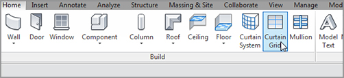
1. On the Build panel of the Home tab, click the Curtain Grid button, as shown in Figure 16.30.
FIGURE 16.30 Click the Curtain Grid button on the Build panel of the Home tab.
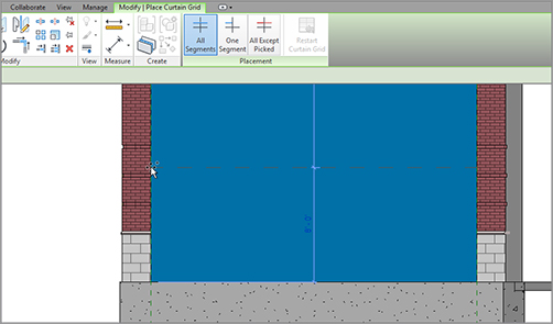
2. On the Modify | Place Curtain Grid tab, click the All Segments button, as shown in Figure 16.31.
3. Move your cursor up the left side of the curtain wall, and pick a horizontal point that is 8´–0˝ (2400mm) up from the base of the wall (see Figure 16.31).
FIGURE 16.31 Picking a point 8´–0˝ (2400mm) up from the base of the wall
4. Press Esc twice, or click Modify.
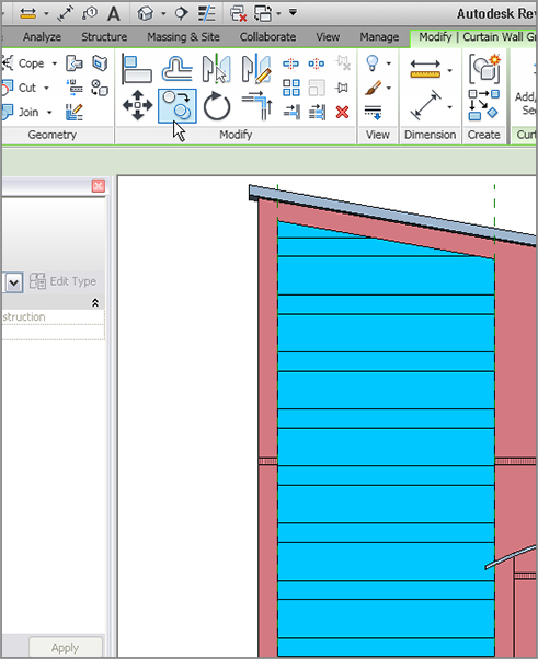
5. Select the horizontal grid.
6.Click the Copy button on the Modify panel.
7. Copy the grid up 4´–0˝ (1200mm).
8. Copy the 4´ grid up 2´–0˝ (600mm).
9. Repeat this pattern until you’ve reached the top of the wall (see Figure 16.32).
FIGURE 16.32 Copying the grids to form the custom curtain wall
10. Click the Curtain Grid button.
11. Slide your cursor along the base of the panel (the grid is extended in a vertical direction).
12. On the Placement panel, click the button for One Segment.
13. Pick the midpoint of the panel. (You should have segmented only the bottom panel.)
14. Click Modify.
15.Select the vertical grid.
16. On the Modify toolbar, click the Move icon.
17. Move the grid to the left 3´–0˝ (900mm).
18. Copy the grid to the right 6´–0˝ (1600mm). Your wall should now look like Figure 16.33.
With the panel broken up, you can begin adding materials. One material you may not think of is an actual door! Yes, in Revit curtain walls, you add a door to a curtain panel as a material.
Adding Materials
Aside from doors, you can add any material that is present in the model. You can even add separate wall systems.
The objective of the next procedure is to add a door to the curtain system; then, you’ll add brick belts that fill the 2´–0˝ sections. Follow these steps:
1. On the Insert tab, click the Load Family button.
2. Browse to Doors, and open the file called Curtain Wall-Store Front-Dbl.rfa.
3. Zoom in to the 6´ × 8´ (1600mm × 2400mm) panel.
4. Hover your cursor at the top of the panel.
5. Press the Tab key twice. When the panel is highlighted, pick it (see Figure 16.34).
FIGURE 16.34Selecting the 6´ × 8´ (1600mm × 2400mm)panel
6. In the Type Selector, pick Curtain Wall-Store Front-Dbl: Store Front Double Door from the Type Selector. A door appears in the panel.
7. Select the 2´–0˝ (600mm) panel above the door.
8. In the Type Selector, pick Basic Wall: Generic – 12˝ (300mm) Masonry.
9. Press Esc.
10. Fill the rest of the 2´–0˝ (600m) bands with the same Generic- 12˝ (300mm)Masonry.
With the panels in place, it’s time to start filling in the mullions—which brings us to the next step: adding mullions to the grid.
Adding Mullions to the Grid
The next logical step is to create the mullions that will be attached to the grid you just added. Because you have a few areas where there shouldn’t be mullions, the job becomes more tedious.
The next example could go one of two ways. One technique adds mullions piece by piece, and the other procedure lets you add mullions all at once and then delete the mullions you don’t need. The following procedure will take the latter approach; you’ll add the mullions all at once and then remove the superfluous mullions. Follow along:
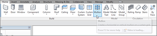
1. On the Build panel of the Home tab, click the Mullion button, as shown in Figure 16.35.
FIGURE 16.35 Click the Mullion button on the Home tab.
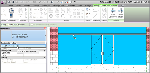
2. In the Properties dialog, choose Rectangular Mullion: 2.5˝ × 5˝ (64mm × 127mm) Rectangular.
3. Pick the grid above the door, as shown in Figure 16.36.
FIGURE 16.36 Place the 2.5˝ × 5˝ (64mm × 127mm) rectangular mullion above the door.
4.On the Placement panel, click All Grid Lines.
5. Pick anywhere on the grid. The mullions are added to the entire system.
6. Press Esc.
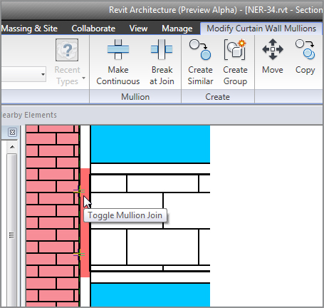
With the mullions added, you’ve actually gone too far! An aluminum extrusion separates the CMU from the adjacent brick. You also need to delete the mullion that appears under the door. The objective of the next procedure is to remove these pieces of mullion:
1. Zoom into an area where the CMU meets the brick, as shown in Figure 16.37.
2. Select the small mullion piece that lies between the brick and the CMU. (You’ll have to press the Tab key several times to accomplish this.)
3. With the mullion selected, notice that you can either modify the join (as shown in Figure 16.37) or press the Delete key and remove the mullion. In this case, delete the mullion. Repeat the procedure for other similar areas.
So, what have you accomplished? You’ve embedded a predefined curtain wall into a radial profile, and you’ve added a curtain system to a giant glass panel by hand. The only thing left to do is to apply a curtain wall to a sloping surface.
Everything you’ve done up to this point has been within a perfectly plumb application. Not everything in architecture is perfectly plumb, however. Suppose you needed a wall that sloped in or out at an angle. Well, gentle readers, let’s get into the world of massing.
Now that you’re finally using 3D for the first time in the book, you need to think in those terms. You have to deal with two dimensions, and then you let Revit project the third. You need to first provide geometry in plan. Second, you provide geometry in elevation. When you have the plan geometry and the elevation geometry, you can blend the two together, creating the third dimension. Let’s get started:
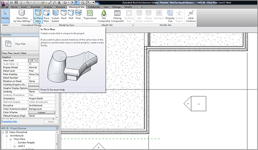
3. On the Massing And Site tab, click the In-Place Mass button (see Figure 16.38). Revit may throw a warning stating it’s turning on the mass visibility. This is good, so pick Close.
4. Call the new mass West Wing Atrium, and click OK.
Let’s take a breather. You’ve satisfied the first criteria of creating a mass element by creating a simple line and arc. This line and arc will be the guide for your vertical geometry to ride along—the path. It’s time to move on to the second dimension: the vertical dimension. Follow these steps:
1. Open the section called West Corridor Section. You can double-click the section in plan, or you can open it from the Project Browser.
2. In the Draw panel, click the reference Plane button, as shown in Figure 16.41.
3. Use Pick Lines, and offset the front face of the wall to the right 2´-0˝ (600mm).
4. With the same command still running, offset another reference plane down 2´-0˝ (600mm) from the bottom of the roof beyond (see Figure 16.41).
Now it’s time to draw the actual shape:
1. In the Draw panel, click the Model line button (see Figure 16.42).
2. In the Work Plane dialog, select Pick A Plane, click OK, and select the wall as shown in Figure 16.42.
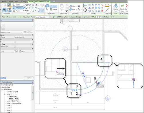
3.On the Options bar, be sure Make Surface From Closed Loops is selected, and be sure the Chain button is selected.
4. Verify that Draw Line is the draw option. Draw a line from point 1 to point 2, as shown in Figure 16.43. (This line is from the bottom of the CMU wall to the bottom of the concrete ledge.)
5. Draw a line from point 2 to point 3, as shown in Figure 16.43.
6. Draw a line from point 3 to point 4, as shown in Figure 16.43.
11.Press the Tab key. When the three lines are highlighted, pick kthe wall. You may have to zoom in a little to tell Revit that you need to make a screen selection.
12. Offset the three lines to the right, as shown in Figure 16.44.
13. Change the offset to 0 in the Options bar.
14. Change the Pick Lines option to Draw Lines.
15. Draw a line at the top and the bottom, closing the loop. See Figure 16.45.
Nice! Two out of the three requirements for 3D are completed: horizontal (plan) and vertical (elevation). The only thing left to do is tell Revit to blend the two together:
1. Go to the default 3D view.
2. Zoom in on the area you’re working in.
3. Hover your cursor over one of the lines of the shape you just drew.
4. Press the Tab key. Revit should select the entire perimeter of the shape.
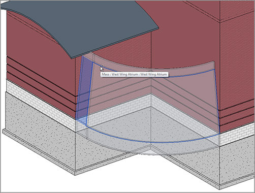
5. With the vertical shape selected, hold the Ctrl key, and pick the reference arc you drew.
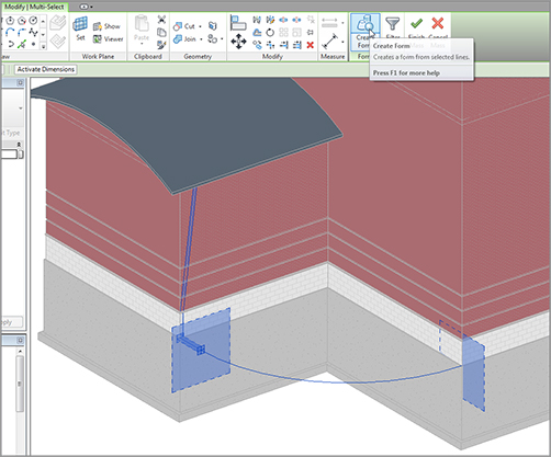
6. Click the Create Form button, as shown in Figure 16.46.
7.When the form is placed, click the Finish Mass button.
8. You should be looking at what is shown in Figure 16.47.
FIGURE 16.46 Selecting the objects and creating the form
Now it gets fun! It’s time to begin adding walls to the shape. In Revit Architecture, there are three ways to add walls to a model: draw them in, pick lines to add them, or pick faces. You have some pretty sweet faces eager to host some walls, so let’s dig in. Follow these steps:
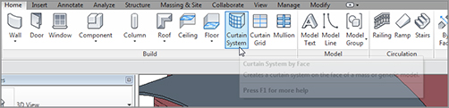
1. On the Home tab, click the Curtain System button, as shown in Figure 16.48.
FIGURE 16.48 The Curtain System button on the Home tab
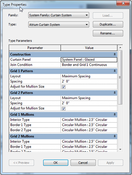
2. Click Edit Type.
3. Click Duplicate, and call the new system Atrium Curtain System.
4. For the Curtain Panel, select System Panel: Glazed.
5. Set Join Condition to Border And Grid 1 Continuous.
6. Layout for Grid 1 pattern is Maximum Spacing, and Spacing is 2´-0˝ (600mm).
7. Select Adjust For Mullion Size.
8. Repeat the settings for the Grid 2 pattern.
9. For the Grid 1 and Grid 2 mullions, select Circular Mullion : 2.5˝ (64mm) Circular for Interior Type as well as the Border 1 and 2 types, as shown in Figure 16.49.
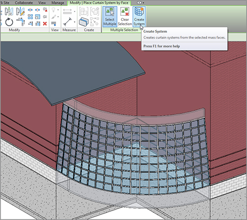
10. Click OK.
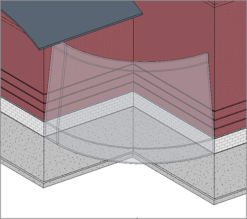
11. Pick the two faces of the mass, as shown in Figure 16.50.
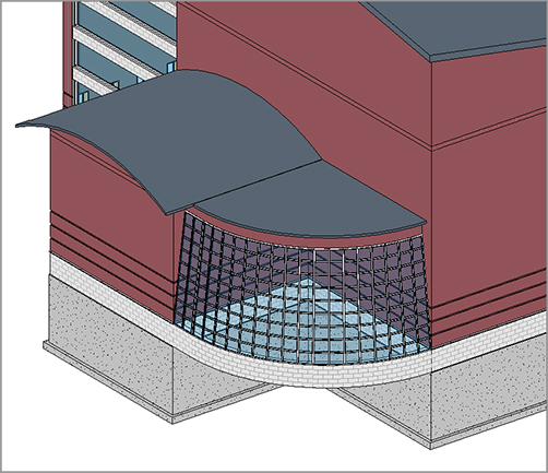
12. Click the Create System button, and you have it! See Figure 16.51.
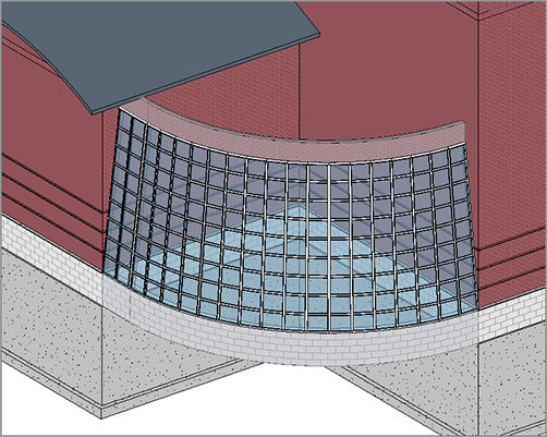
I think you’d better add a roof, just to close out the exercise. Although it’s superfluous to this example, it will bother all of us throughout the rest of the book if you don’t. Follow these steps:
1. Go to Floor Plan: Corridor Parapet.
2. Set Visual Style to Wireframe in the View Control toolbar.
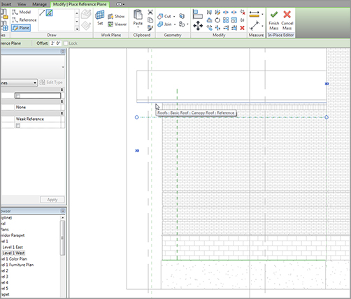
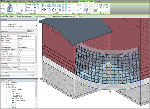
3. On the Home tab, click the Roof button.
4. In the Type Selector, set the roof to Basic Roof: Canopy Roof.
5. Set Base Offset from Level to -4´-1/2˝ (-114mm).
6. Make sure the Defines Slope button is deselected in the Options bar.
7. Make sure the Pick Walls option is selected in the Draw panel.
8. Set the overhang to 1´-0˝, (300mm) and pick the walls of the atrium.
9. Set the offset to 0, and pick the walls of the building.
10. Clean up any overlapping corners. Your sketch should look like Figure 16.54.
As you can see, you’re just at the doorway of massing. Literally. There is no way to get into the little portico you just created. In the next chapter, we’ll discuss creating families, and we’ll delve much deeper into the massing that comprises the components built within Revit Architecture 2012.