As you’re probably becoming acutely aware, having the right content will make or break a Revit project. I’m sure you’re also very aware that, other than the content Autodesk has provided and the content you downloaded from this book’s web page, you don’t have anywhere near the amount of content you need to start a project! That being said, it’s time to buckle down and dig into how Revit works, and see how having adjustable, parametric families will turn you into a Revit fan for life.
The first item we’ll tackle is how to create a basic family. We’ll start with the creation of a wall sweep and then move on to creating an arched doorway. As you become fluent with these two basic family types, you will really start to become quite fast at creating families.
You have to start somewhere. To be honest, no good family is “basic,” but some are easier to create than others. The concept is the same, however.
Essentially, a family has three fundamental components:
Reference Planes Yes, reference planes drive the family. Look at these as the family’s skeleton.
Constraints Constraints are dimensions with a parameter associated with them to give the skeleton its flexibility.
3D Massing 3D massing is locked to the skeleton. We’ll call this the skin. Corny, I know, but it gets the point across.
To get started, you need to figure out where to get started. Any family that you want to insert into a Revit model must begin with a template. Choosing the correct template, as you’ll soon discover, will make your life much simpler.
The objective of the next procedure is to start a new family by choosing a template in Revit. Follow these steps:
1. Open Revit Architecture.
2. In the Recent Files screen, click the New link in the Families row in the middle of the dialog (or click the Application button and select New Family).
3. In the Imperial Templates (Metric Templates) folder (where the family templates are stored), select Profile-Hosted.rft (Metric Profile-Hosted.rft), and then click Open.
As mentioned earlier, first you’ll notice the reference planes. A good family starts and ends with these. Next, you’ll notice some text. Revit adds advice in each of its family templates. After you read the advice, you can delete it. You’ll do that in a moment, but first let’s add reference planes to the family.
Adding Reference Planes to a Family
The one bad thing about creating a family is that you can get away with doing so without using reference planes at all. This is unfortunate, because a family made with no (or not enough) reference planes will be faulty at best. I’ve learned that lesson the hard way. Although it may seem redundant to add reference planes, I strongly advise you to use them and use them often.
The objective of the following procedure will be to offset some reference planes to create the wall sweep. Follow along:
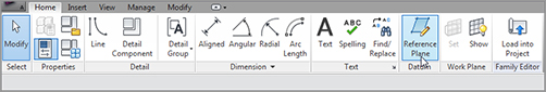
1. On the Datum panel of the Home tab, click the Reference Plane button, as shown in Figure 17.1.
FIGURE 17.1 The Reference Plane button on the Home tab
2. In the Draw panel, click the Pick Lines button.
3. On the Options bar, set Offset to 1´–0˝ (300mm).
4. Hover your cursor over the center, vertical reference plane. When the blue reference line appears to the right of the vertical plane (as shown in Figure 17.2), pick the center reference plane. You now have two vertical reference planes spaced 1´–0˝ (300mm) apart.
5.With the Reference Plane command still running, pick the horizontal reference plane, and offset it down using the same offset increment of 1´–0˝ (300mm). Your family should resemble Figure 17.3.
These two reference planes represent the body of the sweep. The objective of the following procedure is to add two more secondary reference planes for more control over the family. Follow these steps:
1. Set Offset to 2˝ (50mm).
2. Offset the top horizontal reference plane down.
3. Offset the left vertical reference plane to the right (see Figure 17.4).
FIGURE 17.2 Adding a second vertical reference plane
With the reference planes in place, you can move on to adding dimensions to them. After you add the dimensions, you’ll add parameters to those dimensions to make your family flexible when you add it to the model.
Adding Dimensions and Parameters to a Family
We’re now looking at one of the most outstanding features of Revit. Because you can create a parametric component easily and then allow the end user to change the dimensions, you can put your company into overdrive in terms of pushing BIM through and having success with Revit.
The first procedure involves adding dimensions to the reference planes you’ve already put in place. The second procedure will add parameters to the dimensions you’ve added. Follow along:
1. On the Measure panel of the Modify | Place Reference Plane tab, click the Aligned Dimension button.
2.Add a horizontal dimension from the left reference plane to the right reference plane. The dimension should be 1´–0˝ (300mm).
3. Add a second dimension from the top reference plane to the bottom reference plane. The dimension should be 1´–0˝ (300mm).
4. Add a dimension from the left reference plane to the 2˝ (50mm) reference plane to the right.
5. Add a dimension from the top reference plane to the reference plane 2˝ (50mm) down (see Figure 17.5).
FIGURE 17.3 Adding a second horizontal reference plane downward
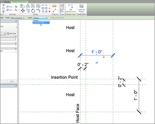
The next step is to make this family come alive! Because you’re in the Family Editor, when you select a dimension you can choose to add a label to the dimension. This label is tied to a parameter that can be modified.
With the reference planes in place and the dimensions set with the parameters, it’s time to go behind the scenes and see how these families operate by examining the family types and adding formulas to the parameters.
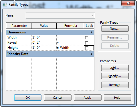
The Type Properties Dialog
Within the Family Editor lies a powerful dialog that lets you organize the parameters associated with the family you’re creating. The Type Properties dialog also allows you to perform calculations, and to add increments in an attempt to test the flex of the family before it’s passed into the model.
The objective of the following procedure is to open the Family Types dialog and configure some parameters. Follow along:
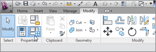
1. On the Properties panel, and click the Family Types button, as shown to the left in Figure 17.8.
FIGURE 17.8 The Family Types button on the Properties panel
2. In the Family Types dialog, click into the Formula cell in the Height row.
3. Type Width, and press the Tab key (see Figure 17.9).
FIGURE 17.9 The Height parameter is now constrained to the Width parameter.
4. Click into the Width value (the area in the Width row that has the 1´–0˝ (300mm) increment).
5. Change Width from 1´–0˝ (300mm) to 6˝ (150mm). The Height value changes too.
6. Click OK. The 1´–0˝ (300mm) dimensions are reduced to 6˝ (150mm).
7. Click the Family Types button.
8. Change the Width back to 1´–0˝ (300mm).
9.Click Apply. The dimensions update in the drawing area.
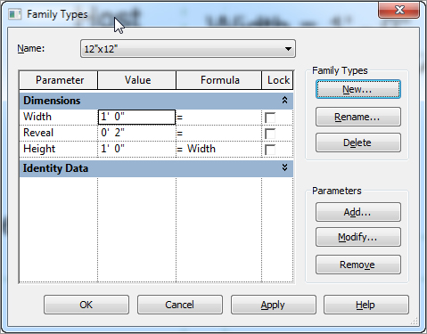
10. Click the New button in the Family Types area, as shown in Figure 17.10.
11. Call the new type 12˝ × 12 ˝ (300mm × 300mm), and click OK (see Figure 17.10).
13. Call the new type 6˝ × 6˝ (150mm × 150mm), and click OK.
14. Change Width to 6˝ (150mm).
15. Change Reveal to 1˝ (25mm).
16. Click Apply. The reference planes and dimensions update.
17. Change Type back to 12˝ × 12˝ (300mm × 300mm).
18. Click OK.
19. Click Save, and save the family somewhere you’ll be able to retrieve it later. Name the file Cove sweep.rfa.
Now that the reference planes and parameters are in place, you can flex the family to make sure that it will work properly when you load it into the project.
The next step is to add the physical lines that form the perimeter of the sweep. Given that this was created using the hosted profile template, the actual family will merely be a 2D profile. The family won’t become a 3D object until you pass it into the model and use it as a wall sweep.
The objective of the next procedure is to draw the perimeter of the cove sweep. Follow these steps:
1. On the Detail panel of the Home tab, click the Line button.
2. Draw a line from the intersection labeled 1 in Figure 17.11 to the intersection labeled 2.
3. Draw a line from point 2 to point 3.
4. Press Esc.
5. Draw a line from point 1 to point 4.
6. Draw a line from point 4 to point 5.
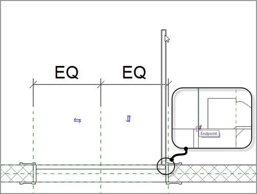
7. On the Draw panel, click the Start-End-Radius Arc button, and draw an arc from point 5 to point 3. When the two points are snapped in place, move your cursor to the left until the radius snaps into place (point 6). Your family should look like Figure 17.11.
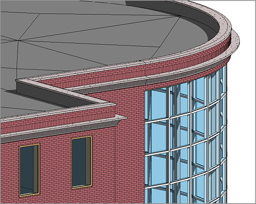
Now you can load the family into the model and use it as a wall sweep. This is when you get to enjoy the fruits of your labor. To get started, open the building model you’ve been working on. If you missed the previous chapter, go to the book’s web page at www.sybex.com/go/revit2012ner. From there, you can browse to Chapter 17 and find the file called NER-28.rvt. Follow along with these steps:
1. Open the Cove Sweep file (if you’ve closed it).
2. On the Family Editor panel, click the Load Into Project button.
3. In the NER-28 project, select one of the exterior walls in the east wing.
You’re getting a taste for what you can do with this powerful tool. And as you can see, you’re only scratching the surface of the fun you can have. Now you’re ready to try a real family!
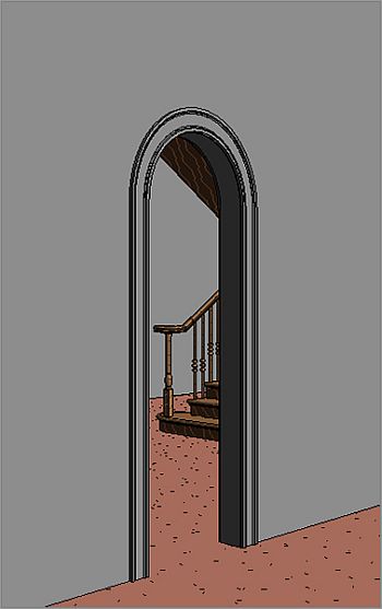
The next section of this chapter will be spent creating an opening with a radial header. Think about the lessons learned in the cove sweep, and let’s dig in.
The “easy” family is out of the way, and it’s time to begin blending the procedures of creating a parametric frame with actual 3D extrusions and sweeps. These 3D extrusions and sweeps will behave exactly like the cove family you just made. When you learn how to create one type of family, that knowledge transfers to the next.
This section of the chapter will start with a blank door template and proceed with modifying a wall cut. Then, you’ll add casing, a jamb, and a door.
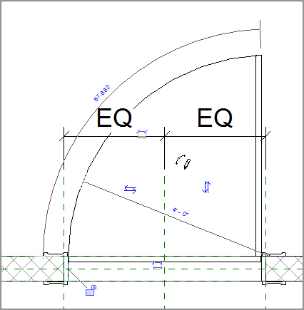
The objective of the next procedure is to start a new family and create a door opening with an arched top. Follow along:
1. Click the Application button, and select New Family.
2. Find the template called Door.rft (Metric Door.rft), and click Open.
3. The first thing you’ll notice is that quite a bit of work has been done for you. This is great, but you don’t need all the items in the template. Select the doorjambs, as shown in Figure 17.13, and delete them from either side of the door.
FIGURE 17.13 Deleting the jambs from either side of the door
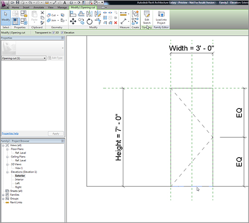
4. In the Project Browser, find the Exterior elevation under the Elevations (Elevation 1) category, and open it.
5. In this view, you see a wall and an opening. Select the bottom of the opening, as shown in Figure 17.14.
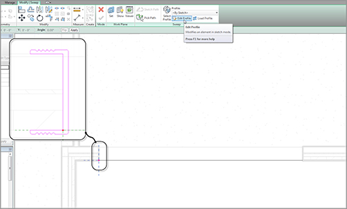
6. On the Options bar, click Transparent In: Elevation.
7.Click the Edit Sketch button on the Opening panel (see Figure 17.14).
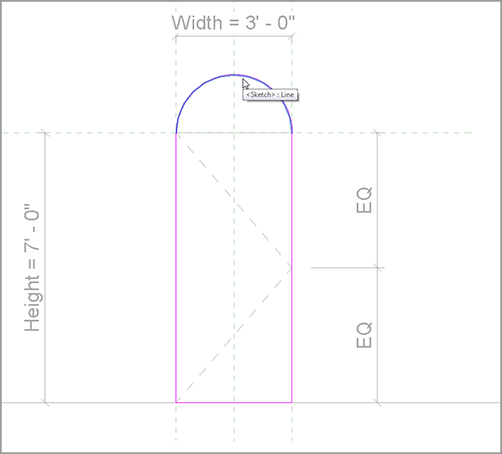
10. Delete the leftover top line. Your door opening should be a continuous perimeter.
11. Click Finish Edit Mode.
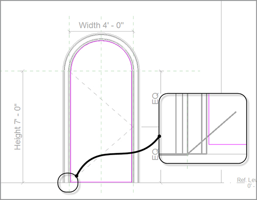
With the opening in place, you can begin testing. Yes, you need to test the width to see if the actual radial top will behave as expected. Taking the time to do this now is an extremely small concession to the pain of deleting half the family and later trying to find what broke the family.
The objective of the next, short procedure is to test the width of the opening:
1. Click the Family Types button on the Properties panel.
2. Change the value for Width to 4´–0˝ (1200mm).
3. Click OK.
4. Verify that the arc behaved as expected. If it didn’t, you need to reedit the opening and make sure you’re snapped to the correct points.
I told you that would be quick. That is all the time it takes to make sure your family is good to go up to this point.
Now it’s time to add some components to the family. The first item you’ll tackle is the doorjamb. You’ll do this by creating a solid form and then a solid extrusion.
Creating a 3D Extrusion within a Family
Other than the curtain wall you applied to a face of a mass in the previous chapter, you’ve been working in this huge 3D program without doing a single 3D operation. Well, that has come to an end. At some point, you’ll need to deal with 3D and massing. When it comes to learning families, you can’t avoid it.
But 3D within a family is slightly different than any 3D item you may have created in the past. The wonderful thing about creating 3D items within a family is that these items are fully adjustable after they’re created.
The objective of the next procedure is to create a doorjamb using solid extrusion. You’ll then lock the faces of the extrusion to the walls so the family will adapt to any wall thickness when passed into the model. Follow these steps:
1. Make sure you’re in the exterior elevation.
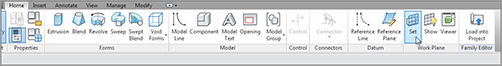
2. On the Forms panel of the Home tab, click the Extrusion button.
3. In the Work Plane panel, click the Set button, as shown in Figure 17.16.
FIGURE 17.16 The Set button in the Work Plane panel
4. In the Work Plane dialog, click Pick A Plane, and click OK.
5. Pick the face of the wall, as shown in Figure 17.17.
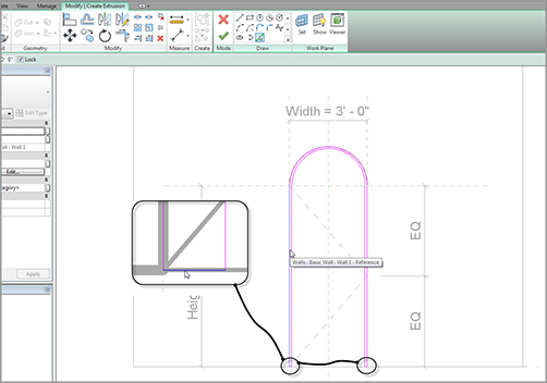
6. Now that the work plane has been set, click the Pick Lines icon on the Draw panel.
7. On the Options bar, select the Lock toggle, as shown in Figure 17.18.
8. Pick the inside face of the opening (see Figure 17.18).
9. After you pick the inside face, change the offset on the Options bar to 1˝ (25mm).
FIGURE 17.17Setting the face of the wall as the work plane
10. Pick the same lines, offsetting the inside face of the jamb into the opening 1˝ (25mm).
11. Zoom in to the bottom of the jambs.
12.Set the offset on the Options bar to 0.
13. Draw a line connecting the bottom of each jamb (see Figure 17.18).
14. In the Properties dialog, make sure the type is set to Extrusion, as shown in Figure 17.19.
15. Set Extrusion End to -3˝ (-75mm), as shown in Figure 17.19.
16. Click the small button to the right of the Material row (see Figure 17.19).
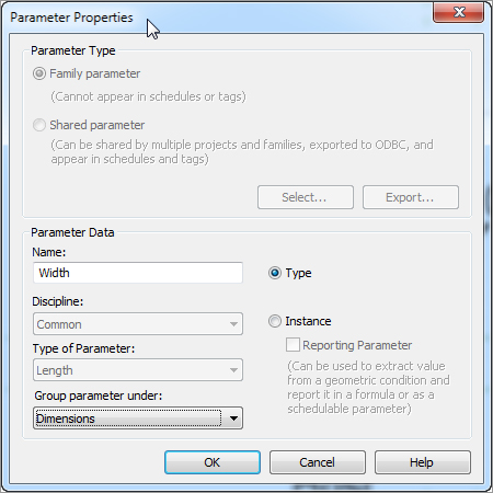
17. Click Add Parameter in the lower-left corner of the dialog.
18. Name the parameter Jamb Material.
19. Keep it grouped under Materials And Finishes.
20. Keep it a Type parameter.
21. Click OK.
22. The Material field is no longer active. Click OK again, and then click Finish Edit Mode.
FIGURE 17.19Clicking the button to add a material parameter
What did you just do? By not selecting the actual material in the properties of the extrusion, you created a parameter so users can specify whatever material they deem necessary. This is a valuable step in family creation: it’s called flexibility.
Speaking of flexibility, this jamb is held at a steady 3˝ (75mm). This is an incorrect value and will remain static unless you do something about it. You’ll do so right now. The objective of the next procedure is to align the inside face of the jamb with the inside face of the wall and to lock that alignment in place. Follow along:
1. Go to a 3D view, and make sure you’re spun around so you can see the inside face of the wall where the jamb doesn’t align.
2. Click the Align button on the Modify tab, as shown in Figure 17.20.
3. On the Options bar, select Wall Faces for Preference.
4. Pick the inside face of the wall.
5. Pick the inside face of the jamb.
6. Click the open padlock icon that appears (see Figure 17.20).
7. Press Esc.
8. Click the Save icon.
9. Save the door into a directory where you’ll be able to find it.
FIGURE 17.20Aligning and locking the inside face of the jamb to the wall
10. Call it Arched Door.rfa.
11. Make sure your project is open.
12. In the Arched Door.rfa file, click Load Into Project. Note that if you have more than one project or family open, Revit will make you choose a model into which to load the family. Be sure to pick your project file.
13. In the model, open the Level 1 West dependent view.
14. On the Home tab, click the Door button.
15. Insert the new door in the wall, as shown in Figure 17.21. (Don’t worry too much about placement.)
17. In the Properties dialog, click Edit Type, and observe the parameters. Look familiar? You created them!
18. Click OK.
19. Go back to the door family.
Wow! So this thing actually works. Good deal. The next trick is to add some casing to the outside of the frame. To do so, you’ll have to use a solid sweep.
Creating a 3D Sweep within a Family
Going along the same lines (literally) as the extrusion, you can create a situation where you sketch a path and extrude a profile along that path. The trick is to make sure this sweep can flex along with the door.
The objective of the next procedure is to create the door casing by using a 3D sweep. Follow these steps:
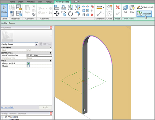
1. Go to a 3D view (if you aren’t there already), and position the view so it looks like Figure 17.22.
2. On the Home tab, click the Sweep button.
3.On the Sweep panel, click the Pick Path button.
4. Pick the inside corner of the jamb starting with the left side (see Figure 17.22).
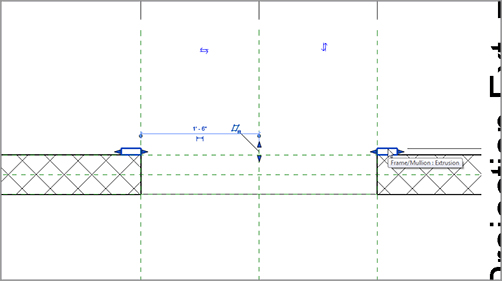
6. On the Sweep panel, click the Load Profile button.
7. Go to the Profiles folder, and select Casing Profile-2.rfa.
8. Click Open.
9. In the menu on the Sweep panel, click the Profile drop-down, and select Casing Profile 2:5 1/2˝ × 13/16˝ (the red dot is replaced with the actual profile).
10. On the Options bar, type -0´–5 3/4˝ (-145mm) for the Y offset. The profile is pushed back onto the wall with a 1/4˝ (6mm) reveal.
11. Click Finish Edit Mode. Select the new sweep.
12. In the Properties dialog, click the small button to the right of the Material category.
13. Click Add Parameter.
14. Call the parameter Casing Material.
15. Group it under Materials and Finishes.
16. Click OK twice.
17. Repeat steps 2 through 11 on the other side of the door. (Don’t try to mirror the sweep, It won’t work.)
18. Save the family.
19. Load it into the project.
20. In your model, select the door.
21. In the Properties dialog, click Edit Type.
22. Change the Width value to 3´–0˝.
23. Click OK.
Your door is still working properly and looks better, as shown in Figure 17.23.
Let’s move forward and begin working on adding a door to the family. The biggest challenge here will be the plan swing representation; but with a few new items to learn, this will be no problem.
The objective of the next procedure is to add a door, a stop, and some plan symbolic linework. Follow along:
1. Open the door family.
2. Go to the exterior elevation.
FIGURE 17.23The finished sweep. If you’d like, go ahead and create a new camera view of this door.
3. On the Home tab, click the Extrusion button.
4. On the Draw panel, click the Pick Lines icon.
5. Set the offset to 1/8˝ (3mm).
6. Offset the two sides and the radial top of the jamb extrusion to the inside.
13. Keep it categorized under Materials And Finishes.
14. Click OK twice
15. Click Finish Edit Mode.
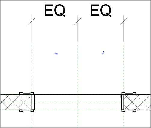
16. In the Project Browser, go to the Ref. Level floor plan view.
17. Click the Thin Lines button on the View tab and your door should look like this figure.
18. Load the door into your project. (Click Yes to overwrite the door that is there.) Verify that the door looks correct.
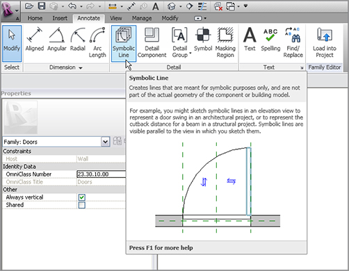
Now that you’ve created the door, you can fix up the plan view. You need to add a door swing. In addition, you don’t want to see the door panel in plan, so you can create a view state to turn it off in the plan view.
The objective of the next procedure is to create a door swing and to make the door panel invisible in plan. Follow these steps:
1. Go back to the door family. On the Annotate tab, click the Symbolic Line button, as shown in Figure 17.26.
7. Load it into the project. If it didn’t explode, your door is complete!
As you can see, it isn’t all that difficult to create a family. This topic could be a book within a book. Start experimenting with your own families. If you run into a snag, send me an email at ewing@cscos.com, and we can work on it.
The next type of family we’ll study is one that literally can’t be avoided. Eventually, you’ll need the surrounding geometry of the model to create the family. This is called an in-place family.
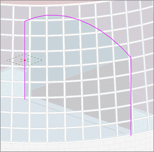
An in-place family gives you the best of both worlds. When you start the In-Place Family command, your model turns into the Family Editor. You can make a family exactly the same way you just did, except that it’s native to the model. Many times, you’ll need this flexibility when you have a family that you’ll never use again in any other building. This also gives you the flexibility to create custom content that can’t be created using the conventional Revit commands.
To create an in-place family, follow along with this procedure:
1. Open the model you’ve been working on.
2.Open the section view called West Wing South Wall Section. You’re in the atrium.
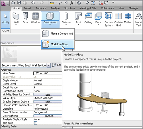
3. On the Home tab, click Component Model In-Place, as shown in Figure 17.29.
The moral of the story is this: when you have a custom situation within the model that can’t be created using the conventional Revit tools, create an in-place family. You should make it as flexible as possible, and give the user some choices, such as materials, so anyone can manipulate the family as if Autodesk provided it.