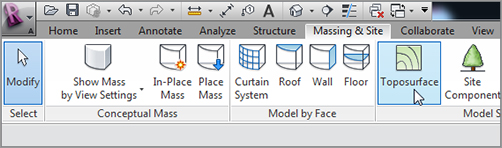
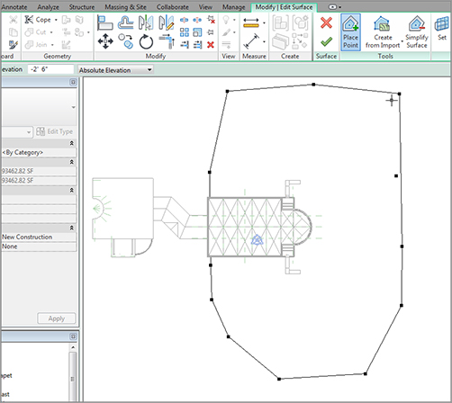
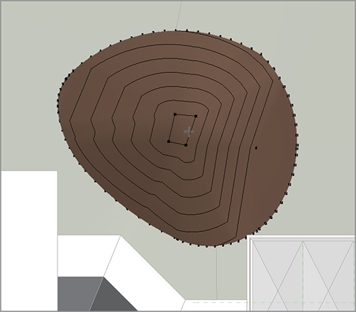
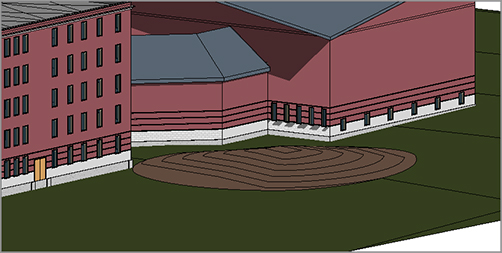
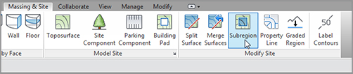
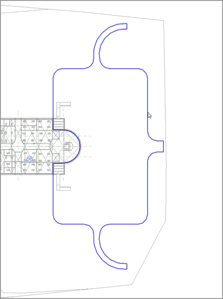
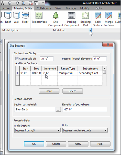
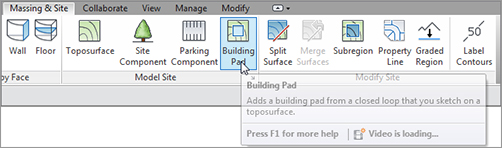
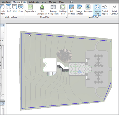
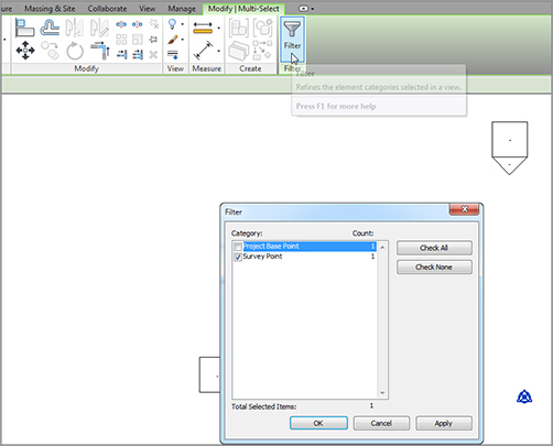
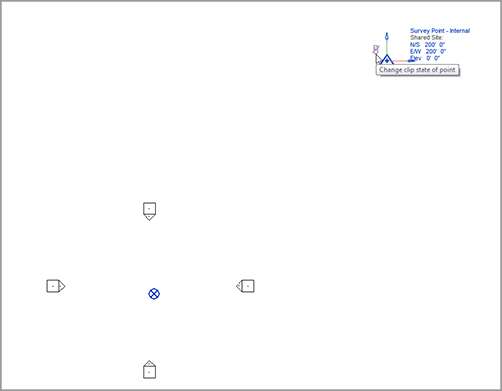
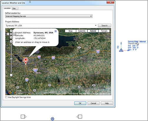
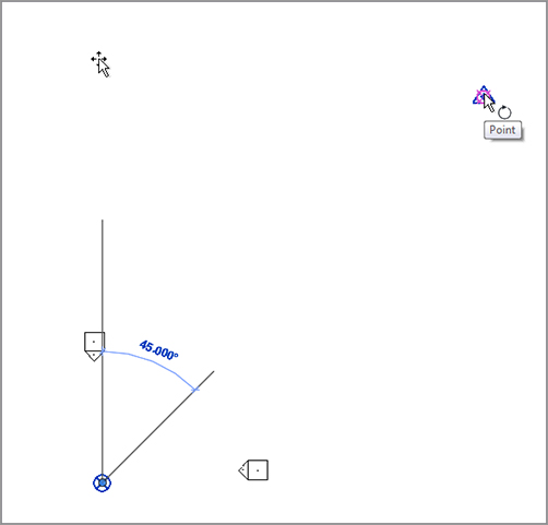
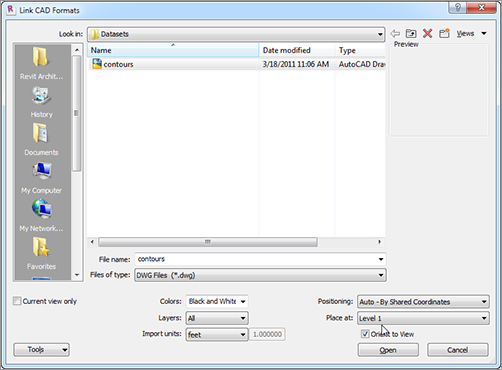
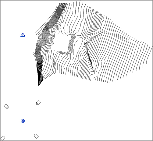
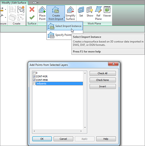
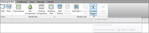
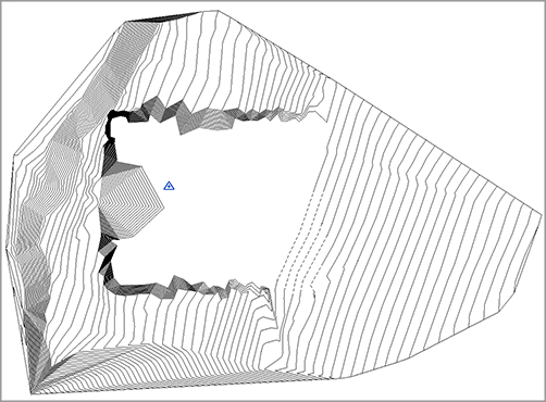
You might be asking yourself if there is a fourth Revit. No. It would be nice if there was a “Revit Civil,” but there isn’t such a thing. So, we’re left to our own devices when it comes to adding a site to a model. This is fine, because in many cases, Revit is well equipped to take on the challenge. Unfortunately, also in many cases Revit is dependent on AutoCAD or MicroStation to provide a real-case scenario for a site that can be imported (similar to importing a plan or a detail). Fortunately, Revit provides tools to add a topographic surface to an imported CAD site. To get started, let’s do something easy, and then migrate into the more difficult areas such as importing a CAD file. The first item you’ll tackle will be to start a site using datum points that you’ll manually pick using the Toposurface function on the Ribbon’s Massing & Site tab. Let’s get cracking. To get started, open the model you’ve been working on. If you missed the previous chapter, go to the book’s web page at www.sybex.com/go/revit2012ner. From there, you can browse to Chapter 18 and find the file called The objective of the next procedure is to add a topographical surface by choosing datum points and elevations. Follow along: FIGURE 18.1 Click the Toposurface button on the Massing & Site tab of the Ribbon. FIGURE 18.2 Adding the first contours Next, let’s see how you can modify a site after you create it. You’ll have to deal with the fact that the ramps at the west entry are buried in your site now. FIGURE 18.3 Adding the second contour to the site FIGURE 18.4 Adding the third set of contours FIGURE 18.5 The toposurface Because you must always make modifications to a toposurface, you need to learn how to do so. The method is basic. Select the site, click Edit, and away you go! The objective of the next procedure is to modify the Toposurface to allow for the ramps to land on earth. Follow these steps: FIGURE 18.6 Adding the 0 elevation points Excellent! You’re getting the hang of this. Next, you need to create some raised areas (small hills) where you can eventually add some plantings and different materials. The problem is, to create a small hill, you need the site to sharply rise to the new elevation. To achieve this, you have to physically split the surface. When you need to make a drastic change to the surface’s elevation without influencing the rest of the site, you must split the surface. Just to warn you up front, be deliberate about when and where you do this, because you’re physically cutting a hole in the surface and adding a secondary toposurface to the void. Although you can merge these surfaces back together, in some situations it can be difficult to merge cleanly. The objective of the next procedure is to split the toposurface and create smaller toposurfaces. Follow along: FIGURE 18.7 The Split Surface button FIGURE 18.8 The split surface sketch Now you can manipulate this surface without influencing the main topography. This is the ideal situation for creating bumps and berms. The objective of the next procedure is to raise this toposurface to an elevation of 4´–0˝ (1200mm). You do this by using a point and placing the datum in the middle of the berm. Follow these steps: FIGURE 18.9 Adding a new datum elevation FIGURE 18.10 The raised area of the site Well, I think you can see where this is going. When you work with sites, just good to have some kind of procedure. This takes us to our next perplexing situation. Suppose you want to keep the contours and the dips and hills intact, and you only want to specify a new material in a subregion of the main topography. Is this possible? Yes, it is! The purpose of a subregion is to match two surface materials so any change in elevation or lateral movement is reflected in both regions. You need this ability for walks and most roadways. When you divide the toposurface into subregions, you give yourself the freedom to manipulate two different materials within the same datum. Another benefit of subregions is that the file size remains as if there was still one toposurface. If you were to split the surface every time you needed a path or a roadway, your file size would bloat. The objective of the following procedure is to create a walkway path using the subregion command. Follow along: FIGURE 18.11 The Subregion button FIGURE 18.12 Sketching the subregion FIGURE 18.13 The sidewalks in 3D How did you do? If you aren’t happy with your parking lot layout, go back and redo it. Not too shabby! There is definitely something missing from this parking lot, though. Perhaps some actual parking spaces would be nice. And a parking island or two would make the parking lot stand out. Adding a site component to Revit is no different than adding a desk or a door. A component is a component, as far as Revit is concerned. As you’ve learned, a component is hosted by a system component. For example, when you’re inserting a window, there needs to be a wall, or Revit won’t allow such a foolish transaction to occur. In Revit, you can host a site component to a level, but it’s a bad idea to do so. When you add a site component, you always want to host that component to the actual topography. The objective of this next procedure is to add parking components and plantings to the Revit model. Follow these steps: FIGURE 18.14 The Site Component button Now that the island is in place, it’s time to add the parking spots. You’ll need an ADA space, and some general parking spaces. Follow along: FIGURE 18.15 Adding the component to the parking lot FIGURE 18.16 The ADA parking space FIGURE 18.17 The parking lot Now that the parking lot is to some level of completion, you can add some trees and shrubs to the site. This is going to be a lot easier! Follow these steps: FIGURE 18.18 Adding the plantings With all the contours and plantings in place, you need to knock out a small maintenance issue. There is a function that will allow you to automatically add contour labels to the site; this is a great feature in Revit Architecture. Because nothing in Revit Architecture is dumb, and you can take advantage of a topographic surface having some smarts as well. Even the contour lines of a site are smart. The objective of this procedure is to examine some site settings and throw some labels into the contours. It’s a quick set of steps, but important nonetheless. To examine the Site Settings, run through the following procedure: FIGURE 18.19 Changing the additional contour increment Now that the contours are in place, it’s time to label them. Luckily, a function in Revit allows you to do this in one shot. All you need to do is draw a line specifying the alignment of the contours, and Revit will add the labels automatically. Follow these steps to add contour labels to the site: FIGURE 18.20 Labeling the contours Next, you need to address a situation that has arisen unbeknownst to you. You see, you never defined any areas that you may not want earth to spill into, such as the basement. This will affect every section you have. You can place a pad to displace the earth in the basement. When you need to displace a volume of earth, you use a tool exclusive to the Massing & Site tab to do so. By placing a building pad into your model, you tell Revit that you want to cut the earth away from this area while still leaving the earth beneath a certain elevation. For example, if you want to remove the earth from the basement (which you’ll be doing), but you still need the earth to exist beneath the basement, you must place a building pad. To place a building pad into the model, follow this procedure: FIGURE 18.21 The Building Pad button FIGURE 18.22 Place the pad to the outside of the wall. FIGURE 18.23 Hiding the pad in the view With the pad in place, you can rest assured that your sections are showing the earth where it’s supposed to be. The next item we’ll cover is creating a property line. In most conventional drafting applications, this involves nothing more than adding a polyline around the site. In Revit, that approach is the same, but the property line can tell you much more about the boundary it’s incasing. If you want to add a property line, Revit provides you with the tool you need. Of course, this is Revit, so you aren’t just adding a dumb line to the model. When you start the Property Line command, Revit will ask you if you want to create the property line either by using bearing distances or by sketching (a sketch can be converted to a bearing table after it has been placed). To add a property line, follow this procedure: FIGURE 18.24 Adding a property line You now have a table of deed data that can be modified as you see fit. The next item on the agenda is a powerful tool when it comes to creating a site in Revit. As nice as it would be to never depend on CAD, most of your topographical information will be coming from the CAD world. Revit has a By Instance function that can facilitate this procedure. Creating a toposurface by instance requires that you import a CAD file. After you do so, you can go to the Toposurface command, which offers the choice to use an imported instance to drape a surface from Revit. To get started, you can either choose a site that was created in CAD that you want to experiment with, or you can go to the book’s web page at www.sybex.com/go/revit2012ner. From there, you can browse to Chapter 18 and find the file called The first thing you need to do is think about coordinates. That’s right: coordinates. You’re bringing in a file from AutoCAD, right? How do you know where this site will be placed? You must consider two things: where the project base point is in AutoCAD, and where the survey point is. When you know these two things, you can more logically work between AutoCAD and Revit. The next set of procedures will show you how to coordinate your Revit site with an AutoCAD site. Let’s get cracking! FIGURE 18.25 Selecting the project datum FIGURE 18.26 Altering the survey point FIGURE 18.27 Setting the site OK, great. Now it’s time to set the project orientation. In Revit, you can rotate the site plan to true north while leaving the other views orientated to project north. Let’s do it: FIGURE 18.28 Orienting the site to true north FIGURE 18.29 Rotating true north FIGURE 18.30 Finalizing the rotation Next, you’ll import a site from CAD. To use an imported instance to create a toposurface, follow these steps: FIGURE 18.31 Changing the link settings FIGURE 18.32 The linked site Because you didn’t know the actual survey point of your site, AutoCAD gave you one anyway. It’s obviously off the grid. You can move the site to a specific point and create an actual survey point in the native AutoCAD file. Follow along: FIGURE 18.33 Saving the shared position back to the drawing It’s time to add a Revit surface to the contours. This is pretty easy, so follow these steps: FIGURE 18.34 Adding the toposurface That would be a difficult toposurface to create entirely within Revit! The next item we need to explore is how to grade a surface, yielding areas of cuts and fills. The process itself is straightforward; but as you’re about to learn, you need to first deal with project phasing. FIGURE 18.35 The new toposurface in Revit This section of the chapter will focus on creating cuts and fills within a site. You do this by lowering and raising points that already exist within the topography. The problem is, after you alter the site, you don’t know which part of the site is original, or existing, and which part is new. The objective of the following procedure is to move the site to an existing phase to prepare it for the grading procedure. Follow along: FIGURE 18.36 The Graded Region button FIGURE 18.37 Selecting a range of points FIGURE 18.38 The site with cuts and fills That’s quite a bit of information regarding sites. It’s nice that Revit allows some level of site manipulation, but it would be nice if there was a Revit Site application. I, for one, could see the value in that.
CHAPTER 18
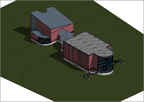
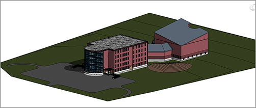
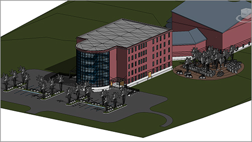
Site and Topography
Adding a Site within Revit
NER-29.rvt.
Modifying a Toposurface
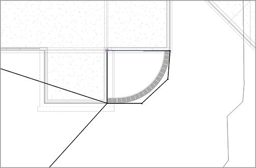
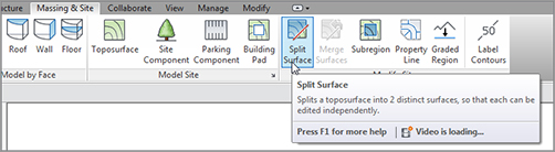
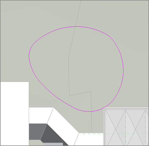
Splitting the Surface
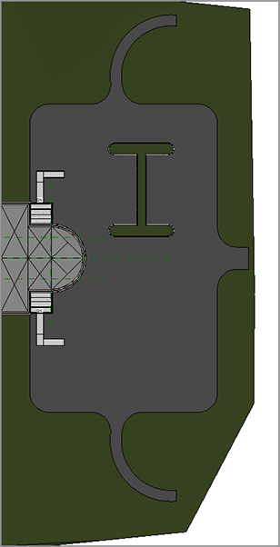
Creating Subregions
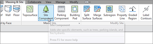
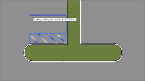
Adding Site Components
Parking directory. It’s inside the Site folder.
Parking Space, click Overwrite The Existing Version.
Adding Contour Properties and Labels
Adding Building Pads to Displace Earth

![]() Elements (see Figure 18.23).
Elements (see Figure 18.23). 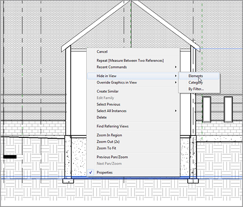
Adding a Property Line
Creating a Toposurface by Instance
contours.dwg.
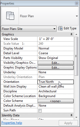
![]() Rotate True North, as shown in Figure 18.29.
Rotate True North, as shown in Figure 18.29. 
Imported Site.rvt.
contours.dwg file you downloaded. (If you have your own site .dwg, that’s fine too.)
.dwg file. You’re now coordinated with your site people. (See Figure 18.33.) 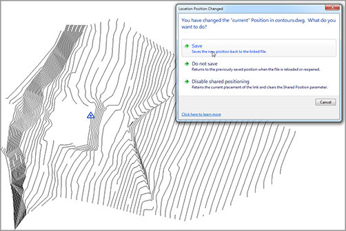
![]() Select Import Instance, as shown in Figure 18.34.
Select Import Instance, as shown in Figure 18.34.
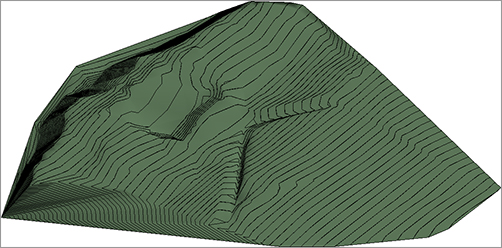
Creating a Graded Region
contours.dwg.

Are You Experienced?
Now you can…