Well, here we are: the chapter you’ve probably been chomping at the bit to get into—and for good reason. The output that you create from this chapter will make your bosses and, better yet, your clients get behind your presentations. As I always say, none of this software is any good if you can’t capture the work to begin with. That being said, in this chapter we’ll focus on creating renderings, adding animations, and providing solar studies based on a project’s geographical location.
The first item we need to tackle is how to go about creating an exterior rendering. Just trying to address the subject of rendering as a whole would convolute the matter. The thing is, when you create a rendering, lighting obviously plays a major role. Day lighting and artificial lighting are two completely different beasts; one will influence the effect of the other. For example, if you’re rendering an exterior scene, there are bound to be windows. If this rendering appears at night or at dusk, the interior lights will be turned on.
The objective of the first section of this chapter is to create a rendering from the exterior of a building using day-lighting scenes, sky, and shadowing to create the rendering you need.
In the previous chapter, you completed one of the most difficult tasks when it comes to creating a proper exterior rendering: rotating a building in terms of true north. It stands to reason that your rendering won’t be accurate if you have a glass curtain wall that is facing north but still have sunlight pouring through it.
To get started, open the model you’ve been working on. If you missed the previous chapter, go to the book’s web page at www.sybex.com/go/revit2012ner. From there, you can browse to Chapter 19 and find the file called NER-30.rvt.
The objective of the first procedure is to create a camera view that you can use for your first rendering. You’ll then adjust the view controls and look at the sunlight effects. Follow along:
1. In the Project Browser, open the Level 1 floor plan.
2. Zoom in on the corridor area in the middle of the building.
3. Add some curtain walls to the corridors, as shown in Figure 19.1. (Come on, I know you can do it.) These are Level 1 to Level 3 with a -6˝ (-152mm) offset from Level 3. You can use the Curtain Wall Storefront.
4. On the View tab, select 3D View Camera.
5. Create a camera view of the area shown in Figure 19.1.
6. When the view opens, rename it Rendering View Corridor.
7. Open the Rendering View Corridor view (it should open automatically).
8. Select the crop region, and widen the view as shown in Figure 19.2.
9. In the View Control bar, set Detail Level to Fine.
FIGURE 19.1Add the curtain walls, and create the camera view.
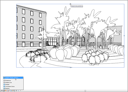
10. Change Visual Style to Realistic.
11. In the Properties dialog, click the Edit button in the Graphic Display Options row (see Figure 19.2).
12. In the Graphic Display Options dialog, click Cast Shadows and Ambient Lighting.
13. Turn on the Gradient background (at the bottom of the dialog).
14. Click the […] button to the right of the Sun Setting field (at the top of the dialog in the Lighting area). Doing so brings up the Sun Settings dialog.
FIGURE 19.2Selecting Graphic Display Options and changing the crop region
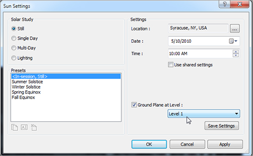
15. Make sure the Still choice is selected for Solar Study, and choose your geographic location for the settings Date, Time, and Location. (I chose Syracuse, NY, and my birthday [05/10 is the default].) You can change these settings if you would like (see Figure 19.3).
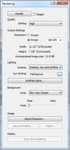
In the Rendering dialog, you’ll see quite a few choices. The choices will vary depending on the scene you’re trying to capture. The next procedure will move through the Rendering dialog from top to bottom.
At the top of the Rendering dialog is a Render button. This is the last button you’ll click: it starts the rendering process. For the rest, follow these steps:
1. For Output Settings, set Resolution to Printer and 300 DPI.
2. In the Lighting category, set Scheme to Exterior: Sun Only.
3. Set Sun to Sunlight From Top Right by clicking the […] button in the Sun Settings row. You’ll need to change Solar Study to Lighting to get this choice.
4. In the Background category, set Style to Sky: Few Clouds (see Figure 19.5).
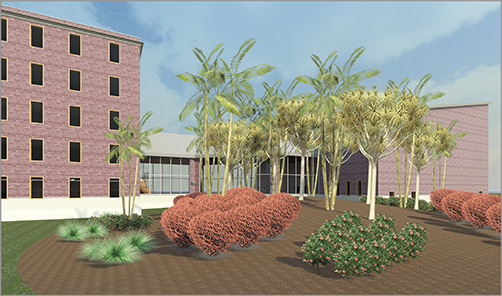
5. Click the Rendering button. After the scene is rendered, it should appear similar to Figure 19.6.
So you waited half your day for this rendering to complete. If you’re like me, you then carefully move your mouse around, wondering how long it will be before something happens and you lose your rendering.
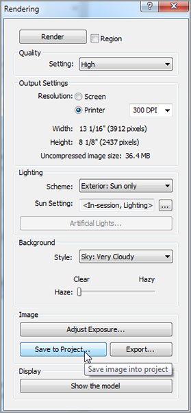
The next procedure will look at how to save the rendering to the model, and also how to export the rendering to an image. Follow these steps:
1. In the Rendering dialog, click the Save To Project button, as shown in Figure 19.7.
2. Call the new rendering view Exterior Rendering at Corridor; then click OK.
3. Click the Export button.
4. Save the file somewhere you can retrieve it. You can choose whatever file format you prefer.
5. At the bottom of the Rendering dialog, in the Display section, click Show The Model. The rendering reverts back to the original graphics style.
6. Click the Show The Rendering button. The rendering reappears.
Let’s try a really cool feature in Revit. The fact is, the sky in Revit just doesn’t cut it. But Revit allows you to add a background image to produce a realistic scene.
The objective of the next procedure is to create a perspective view and render it with a background that comes along with the book. Follow along:
5. At the bottom, select Image from the Style menu in the Background field.
6. Change the background from Sky Cloudy to Image.
7. In the Background Image dialog, click the Image button to browse for the image.
8. Browse to where you put your datasets for this chapter. The file is called Background.tif. If you’re using your own model, go to Google Earth and take a screenshot.
9. For Scale, pick Stretch.
10. Click OK.
11. Set the Quality setting to Draft. (When you aren’t sure how your rendering will look, or whether it will even render, it’s a good idea to render a simple view first and then go for high quality once you’re sure your rendering will be accurate.)
12. Set Resolution to Screen.
13. Click the Render button.
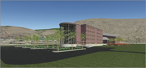
14. Look at the rendering. If you like it, render it at a higher quality, as shown in Figure 19.9.
With the first few renderings under our belts, it’s time to create another exterior rendering. This time, however, you’ll add some lighting and produce the rendering at night. There is nothing like a good before-and-after rendering to sell a project.
The objective of the next procedure is to add some exterior and interior lighting to create a nighttime rendering scene. Follow these steps:
1. In the Project Browser, go to the Level 1 ceiling plan (that’s ceiling plan, in case you missed it).
2. In the Home tab, click the Component button.
3. On the Mode panel, click the Load Family button.
4. Go to the Lighting Fixtures folder.
5. In the Lighting Fixtures directory, go to the Exterior folder.
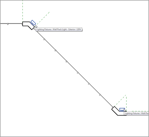
6. Select the family called Wall Pack Light – Exterior.rfa [M-Wall Pack Light – Exterior.rfa], and click Open. If a dialog about loading tags opens, click No.
7. Place the lights at the locations shown in Figure 19.10.
FIGURE 19.12 Adding the interior lighting to the link
Creating Lighting Groups
All too often, you render scenes with no real consideration for the lighting that has been added to the model. Because you lean heavily on Revit to produce accurate scenarios to present to clients, you should spend some time thinking through your lighting before you create a rendering.
The objective of the next procedure is to create two lighting groups and to render the same view using a nighttime setting. Follow along:
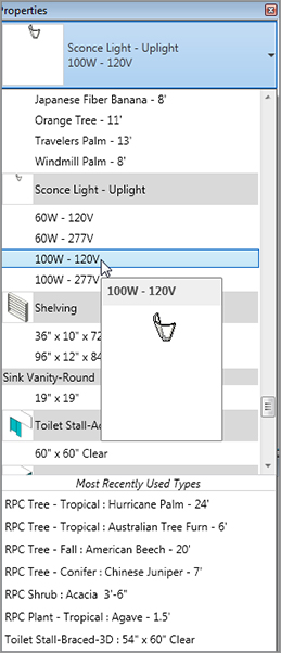
1. Select one of the sconces you just added to the model, as shown in Figure 19.13.
2. On the Options bar, click the Light Group menu, and select Edit/New from the list (see Figure 19.13).
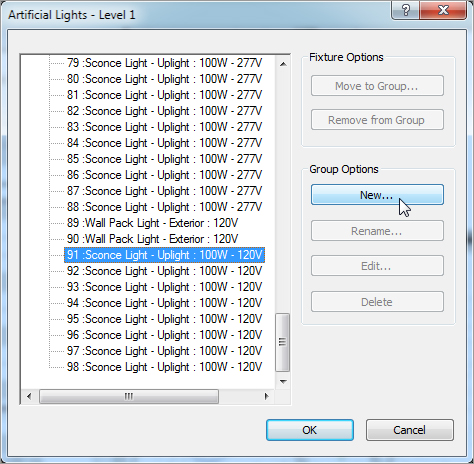
3. In the Artificial Lights – Level 1 dialog, click the New button in the Group Options area, as shown in Figure 19.14.
4. Call the new group Lighting Link.
5. Scroll down to the bottom of the list and locate the lights Sconce Light – Uplight : 100W-120V. Select all of them, as shown in Figure 19.14. Also find the two wall packs and add them to the group as well.
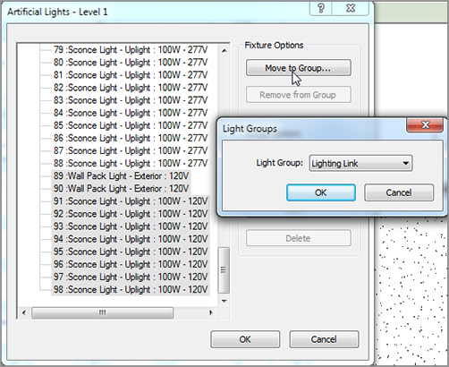
6. Click the Move To Group button under Fixture Options.
FIGURE 19.14Creating a new group, and adding the proper lights
7. Choose the Lighting Link group in the Light Groups dialog, and click OK.
8. Click OK to close the dialog.
9. In the Project Browser, go to the Rendering View Corridor view.
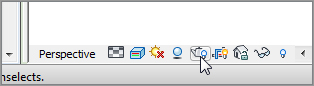
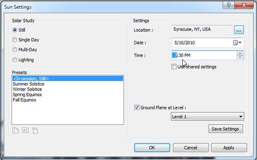
10. On the View Control bar, click the Sun Path button (it’s the picture of the Sun with the small red x), and click Sun Settings.
11. Make sure Solar Study is set to Still, and change the time to 7:30 PM, as shown in Figure 19.15.
If you’re in Syracuse during the winter, it would probably be a good idea to get inside! While you’re in there, you can bring the experience you just gained inside with you to create an interior rendering scene.
You create an interior rendering almost exactly the same way as an exterior rendering. Of course, you’ll definitely use artificial lighting. You’ll also use sunlight, to make sure you account for any natural light that comes into the building.
The objective of this procedure is to create an interior lighting scene using a premade 3D perspective of a hallway:
1. In the Project Browser, find the 3D view called East Wing Corridor Perspective.
2. On the View Control bar, click the Show Rendering Dialog button.
3. Set the Quality setting to High.
4. Set Resolution to Printer and to 300 DPI.
5. Set Lighting Scheme to Interior: Sun And Artificial.
6. Set Sun to Sunlight From Top Right.
7. Make sure Background Style is set to Color.
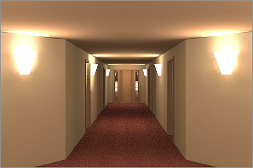
8. Click the Render button. Your hallway should resemble Figure 19.17.
This is getting almost too easy! I suppose you could keep rendering all week, but in the interest of saving some trees, I encourage you to render only a little more. If you run into any trouble during your foray into additional rendering, give me a shout at ewing@cscos.com and ask your question. The winding stairs heading up to the balcony in the west wing would make a nice scene to hang on your cubicle or office wall.
If you feel as though you have enough experience with rendering, let’s jump to the next section and tackle creating a nice walkthrough for a presentation.
For some reason, you can show a client a beautiful rendering of a space or building that you plan to design for them and still be met with a blasé, half-hearted reaction. But if you show them the same space, as though you’re walking through it … well then! The client perks right up.
Although this part of the chapter isn’t crucial to your expertise in Revit, it’s certainly worth a glance. Sometimes the special tools you can pull out of your belt can win a job or impress your friends on a Saturday night.
A walkthrough is a series of points you pick in a sequence in a plan view. It’s sort of like connecting the dots, but these dots will advance a frame as if you were walking to the points you picked.
The objective of this procedure is to create a walkthrough of the building and to export the walkthrough to an AVI file. Follow these steps:
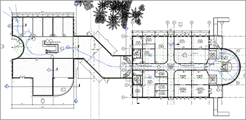
1. Go to the Level 1 floor plan.
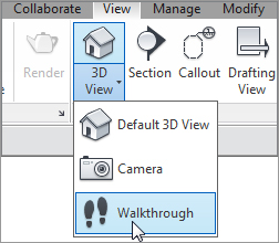
2. On the View tab, choose 3D View Walkthrough, as shown in Figure 19.18.
6.On the Modify | Walkthrough tab of the Ribbon, click Finish Walkthrough.
7. On the Modify | Cameras tab of the Ribbon, click the Edit Walkthrough button.
8. In the Project Browser, find the Walkthroughs category, and open the Walkthrough 1 view.
9. On the Options bar, change the first frame to 1, as shown in Figure 19.21.
10. On the View Control bar, click Realistic.
11. Select the crop region.
12. On the Modify | Cameras tab, click the Edit Walkthrough button (again).
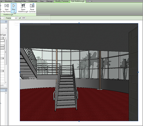
13. On the Modify | Cameras tab, click the Play button, as shown in Figure 19.21.
FIGURE 19.21 Clicking the Play button to start the walkthrough
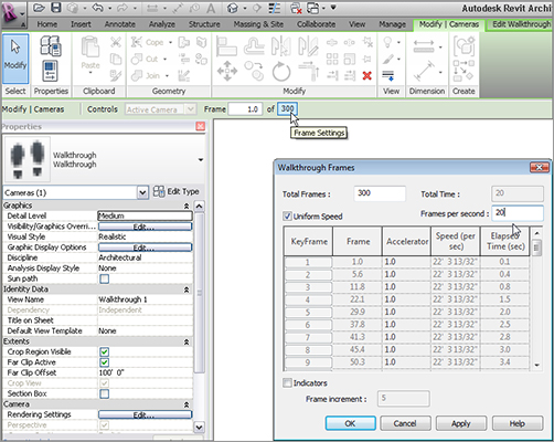
14. When the walkthrough is finished, click the button that contains the value 300 (the number of frames) on the Options bar, as shown in Figure 19.22.
15. In the Walkthrough Frames dialog, change the Frames Per Second value to 20. Click OK.
16. Run the walkthrough again. This time it’s sped up.
The walkthrough is complete. One thing you certainly will be asked is whether you can give the walkthrough to someone to use for a presentation. Luckily the answer is yes, and the person presenting doesn’t have to be Revit-literate or even own the application.
Exporting an Animation
Exporting an animation is a great, but slightly hidden, feature. The Export function isn’t located on the Ribbon—you’ll find it in the Application menu, as shown in Figure 19.23. By exporting a walkthrough, you’re creating an animated vector image (AVI) that will translate the native Revit walkthrough. It’s quick and almost completely painless.
To create an AVI of the walkthrough, follow these steps:
1. Make sure the walkthrough view is open, and click the Application button.
2. Choose Export Images And Animations Walkthrough, as shown in Figure 19.23.
3. Select the defaults in the next dialog, and click OK.
4. Find a location for the file, and click Save.
5. Click OK in the Video Compression dialog. (You’ll have to wait for Revit to go through the walkthrough as it creates the AVI.)
6. Find the AVI, and run it to make sure it works.
With the walkthrough complete, there is one more animation we need to look at. It’s not as cool as the walkthrough, but it’s just as interesting. This animation is called a solar study.
A solar study is a shaded 3D view that provides a time-elapsed visual image of how the building will cast shadows over the course of a day or multiple days.
The objective of this procedure is to create a single-day solar study by specifying the geographical location of your building. Follow along:
1. Go to the view {3D} in the Project Browser.
2. Right-click, and choose Duplicate View Duplicate With Detailing.
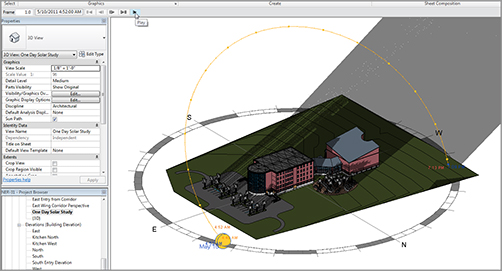
3. Rename the new 3D view One Day Solar Study.
4. On the View Control toolbar, click the Sun Path button, and choose Sun Settings.
5. In the Sun Settings dialog, click the Single Day radio button, as shown in Figure 19.24.
6. Set Location to Syracuse, NY (or wherever you find yourself these days).
7. Change Date to 5/10/2011. Select Sunrise To Sunset. Set Ground Plane At Level to Level 1.
8. Set Time Interval to One Hour (see Figure 19.24).
9. Click OK.
10. Click the Sun Path button again, and turn on the sun path.
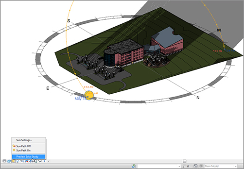
11. On the View Control bar, click the Shadows button, and then select Preview Solar Study, as shown in Figure 19.25. (You can spin the view as shown in Figure 19.25 to check out the different sunlight effects on the building.)
12. On the Options bar, click the Play button, as shown in Figure 19.26.
Animations such as solar studies and walkthroughs are unique features of Revit that aid you in capturing your work. Keep these features in mind the next time you’re working up a proposal or a presentation.
FIGURE 19.26Clicking Play to start the solar study