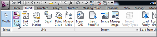
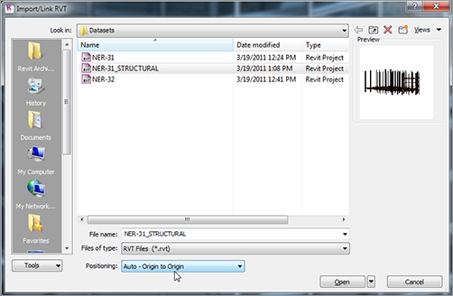
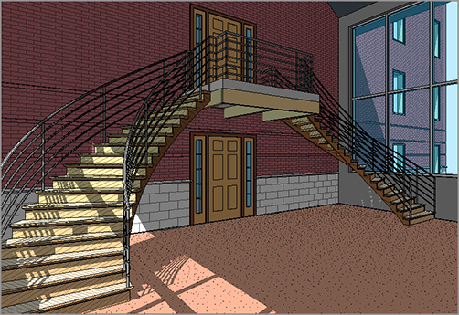
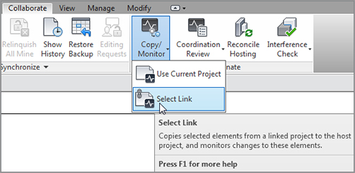
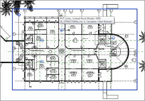
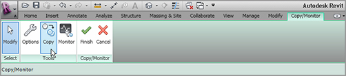
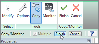
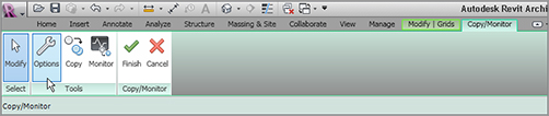
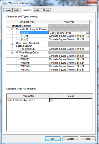
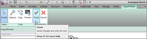
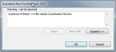
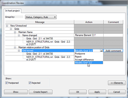
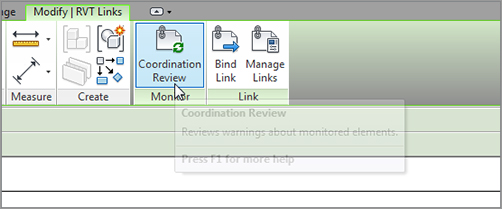
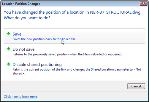
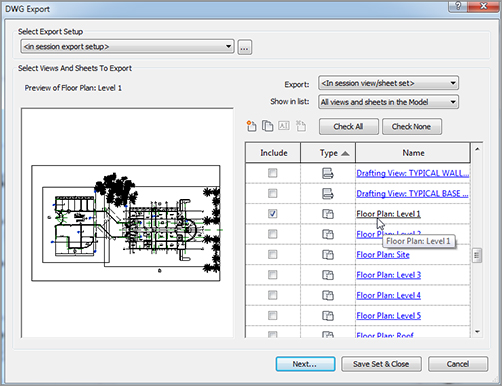
It’s amazing that we’re Up to Chapter 20 and yet I’m sure many readers are still unclear about how BIM fits in here. Yes, most of the previous chapters showed how you benefit from BIM when you change an item in one place and it changes in another, yada, yada, yada. But you were probably sold on the whole “coordinating with your consultants” thing back when you were considering purchasing Revit. Well, here we are. It’s time to tackle that mystical ideology that has put our industry in a loose headlock. The first section of this chapter will focus on the actual event of importing a Revit Structure model. As you start the process, you’ll see that this procedure isn’t unfamiliar if you have any CAD background whatsoever. If you don’t have a CAD background, I think you’ll find these procedures to be intuitive enough to get through importing Revit models with no experience. As you proceed into design development, you must get your structural engineer on board. This consultant may be an external or an in-house resource. Either way, this individual will have a different model that you need to coordinate with. This section will focus on the procedures involved with importing a Revit Structure model. We’ll also cover the concept of creating a live monitoring system with the structure as well as interference detection. To get started, open the model you’ve been working on. If you missed the previous chapter, go to the book’s web page at www.sybex.com/go/revit2012ner. From there, you can browse to Chapter 20 and find the file called The objective of the following procedure is to import and link a Revit Structure model. Follow along: FIGURE 20.1 The Link Revit button on the Link panel of the Insert tab FIGURE 20.2 Pay attention to the choices provided before you click Open. You can now see the wood framing the structural engineer added to support the cantilevered slab, as shown in Figure 20.3. Already you’re seeing the benefits of a collaborative model, and you’ve done nothing more than insert one model into another. This isn’t new technology, and you’re certainly not doing anything profound. The real benefit comes from how you can keep track of what the structural model is doing underneath your model. You can copy items from the structural model and then monitor any changes made from the linked model. This is the definition of BIM. FIGURE 20.3 The supporting framing under the cantilevered slab at the east link I can almost sum BIM up in one command: Copy/Monitor. I hate to break down the most import acronym in our industry since CAD into such simple terms, but building information modeling is the process of monitoring and tracking change, and that process starts right here. The objective of the following procedure is to copy the structural grids and apply a monitoring system that will alert you when the grids have moved. Although this book will focus solely on copying and monitoring the grids, your takeaway will be the experience required to recognize the procedure and the importance of this function. To create a copying and monitoring system, follow these steps: FIGURE 20.4 The Copy/Monitor button on the Coordinate panel of the Collaborate tab FIGURE 20.5 Selecting the link to Copy/Monitor FIGURE 20.6 Clicking the Copy button FIGURE 20.7 The Finish button on the Options bar Now that the grids are being monitored, it’s time to look at what you can copy and monitor from your consultant’s models by configuring the Copy/Monitor settings. By copying the grids into the architectural model, you’re proceeding with the most common, and by far the safest, function of this command. If you do choose to copy and monitor items such as foundations and columns, you can automatically replace the items being copied with an alternate component. For example, you can use Copy/Monitor on a foundation wall that is 12˝ thick but automatically replace it with a foundation wall that is 10˝ thick. Note that this example emphasizes something you would not want to do; be careful while replacing components you get from the structural model. FIGURE 20.8 The copied grids The objective of the next procedure is to look at the Copy/Monitor settings. Follow along: FIGURE 20.9 The Options button on the Tools panel of the Copy/Monitor tab FIGURE 20.10 Changing to Copy Original Type FIGURE 20.11 Clicking Finish You now have a relationship with the structural model. Next, you’ll put this relationship to the test and generate a coordination alert. I suppose you could say that the honeymoon is over! Suddenly you’ve been thrust into a completely different way of working. You have a structural model inserted into your architectural model that will bark at you every time something changes. There’s nothing wrong with that. Sure, occasionally there will be some annoyances, but these occasional irritations are a small concession for being truly tied in with the structure. When something changes in the structural model that is involved with an active monitor, you’ll be alerted. This alert will occur either when you open your model or when you reload the linked Revit file. To review the coordination alert, follow this procedure: FIGURE 20.12 Moving grid 2.2 FIGURE 20.13 Coordination alert FIGURE 20.14 The Coordination Review button on the Monitor panel of the Modify | RVT Links tab FIGURE 20.15 Telling Revit to automatically move and rename the grid FIGURE 20.16 The Coordination Review button A coordination report is an excellent way to track changes, but you’re alerted to these changes only if you have the elements copied and monitored. How are you supposed to know if other elements are colliding with one another? This question is answered by using the Interference Detection function built into Revit. What came first, the chicken or the egg? That’s a tough call. Another tough call is whether the beam comes before the duct or wall. Ask a structural engineer, and they will answer that the beam does in fact come before the wall, the door, or any other architectural appointment. On the other hand, an architect will ask to move or eliminate a structural component. But the fact is, if the architect and the structural engineer are having this argument, that means they know there is an interference, and their disagreement about the chicken and the egg is actually a good thing. You can use interference detection in Revit to keep the contractor from asking such questions. If the contractor is asking questions, then you have a problem, don’t you? It means a collision has occurred that nobody caught. Don’t worry—you can still have the chicken argument, only now it’s called litigation. To use interference detection, you don’t have to do anything more than open a single dialog. There, you can select specific elements that you’re worried about colliding. And in true Revit form, you can create a report and even zoom in on the issue. The objective of the following activity is to find some clashes between the architectural model and the structural model: FIGURE 20.17 The Run Interference Check button on the Coordinate panel of the Collaborate tab FIGURE 20.18 Selecting the components to find in the interference report FIGURE 20.19 The offending items are discovered! That is some good stuff. Lucky for you, your consultants are all up and running on Revit. Oh, they aren’t? What kind of world are you living in? It’s true. Your consultants won’t all be on Revit. If you’re lucky, 1 in 10 uses Revit in the capacity that they’re ready to share a model with you. This is okay—don’t panic. You’re still in a great position. You can easily import from AutoCAD (or MicroStation), and you can export your model just as easily. The first process we’ll delve into is importing an AutoCAD structural floor plan. Although you’ve imported CAD in this book numerous times, you have yet to do so in the context of a coordinated floor plan. The mindset is a little different. And why is that? Because you now care about where this AutoCAD drawing lands in relationship to your model, and you care also about maintaining that relationship. For the CAD file used in the following procedure, go to the book’s web page at www.sybex.com/go/revit2012ner. From there, you can browse to Chapter 20 and find the file called The objective of the following procedure is to import an AutoCAD 2D floor plan, and pin down its coordinates. Follow these steps: FIGURE 20.20 Duplicating the view FIGURE 20.21 Configuring the link FIGURE 20.22 Unpinning and aligning the reference The next step is to make sure the coordinates in the Revit model stay true in the DWG file. With one simple procedure, you can publish the coordinates of the Revit model to the DWG file to ensure accuracy while importing because you had to move the link. Follow along: FIGURE 20.23 Publishing the coordinates So, that’s importing. Now, suppose you need to send your model to clients and consultants who don’t have Revit. This can be taken care of quickly and deliberately. FIGURE 20.24 Saving the coordinates to the AutoCAD file For some of you, this is a nice-to-know subject. But for most of you, this is a need-to-know subject. Taking the plunge into Revit may be something you’re doing alone. Even if you’re using Revit, you may still need the ability to provide CAD drawings based on your models. This section will focus on the process of exporting your Revit model to both 2D and 3D CAD. Most of the time, your deliverable to your clients will be a 2D model. If your consultants aren’t on Revit, usually they aren’t using 3D CAD either. The 2D CAD format is the lowest common denominator. Not that a 2D model is bad—it means you need to export your model in a way that the client can pick it up and run with it. The objective of the next procedure is to export your model to a 2D AutoCAD drawing file. Follow these steps: FIGURE 20.25 Exporting the model to CAD Now that you can export to a flat 2D file, it’s time to export your model as a full 3D entity. The process is similar to exporting as 2D. FIGURE 20.26 Choosing the items to export It’s a shame to dumb down a 3D model to flat 2D CAD. It feels as though you’re taking a step backward each time you do it. When you find yourself in a situation where your consultants are using CAD but are using 3D modeling, you can give them the gift of 3D. The objective of the next procedure is to export a model to 3D CAD. Follow along: As you can see, it’s not a difficult process, but it’s important to know. You’ll often find yourself exporting all your hard work and data to a lesser CAD format as you wait for the rest of the industry to catch up to you!
CHAPTER 20
Importing and Coordinating Revit Models
Linking a Revit Structure Model
NER-31.rvt. You’ll also need to locate the model called NER-31_STRUCTURAL.rvt. Save this file in a location where you can retrieve it.
NER-31_STRUCTURAL.rvt file, but don’t click Open just yet.
Activating Copy/Monitor
Adjusting the Copy/Monitor Options
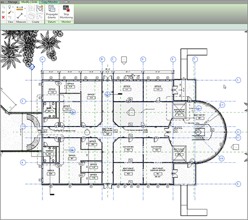
Coordination Alert
NER-31_STRUCTURAL.rvt model.
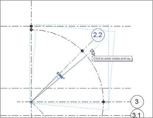
NER-31_STRUCTURAL.rvt model, open the Level 2 structural view; rename grid 2.1 to 2.2, and rotate it 5° as shown in Figure 20.12.

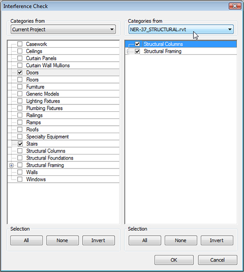
Running Interference Detection
![]() Run Interference Check button, as shown in Figure 20.17.
Run Interference Check button, as shown in Figure 20.17. 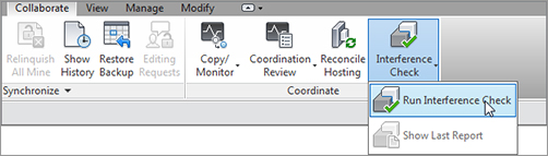
NER-31_STRUCTURAL.rvt file.
Importing and Exporting CAD Formats
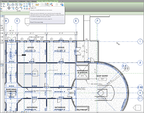
NER-32_STRUCTURAL.dwg. Save this file in a location where you can retrieve it.
![]() Duplicate With Detailing, as shown in Figure 20.20.
Duplicate With Detailing, as shown in Figure 20.20. 
NER-31_STRUCTURAL.rvt model.
![]() Publish Coordinates, as shown in Figure 20.23.
Publish Coordinates, as shown in Figure 20.23. 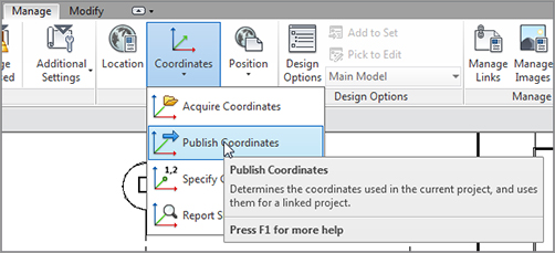
Exporting a Model to CAD
Exporting a 2D Model
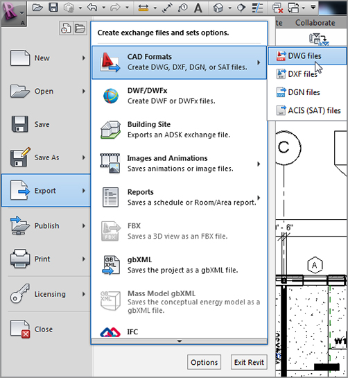
![]() CAD Formats
CAD Formats ![]() DWG Files, as shown in Figure 20.25.
DWG Files, as shown in Figure 20.25.
Exporting the Model to 3D CAD
![]() CAD Formats
CAD Formats ![]() DWG Files.
DWG Files.
Are You Experienced?
Now you can…