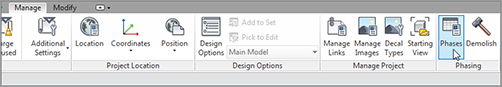
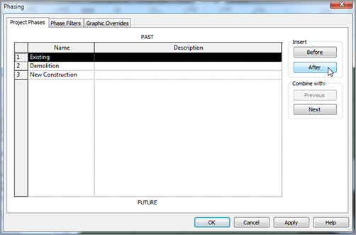
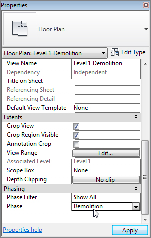
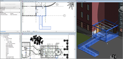
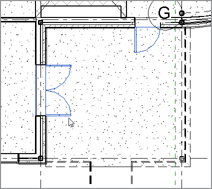
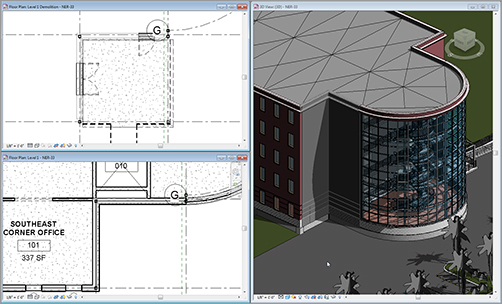
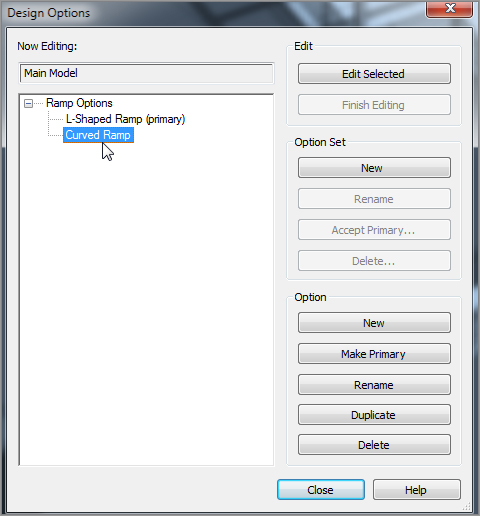
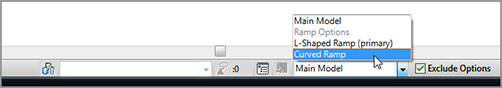
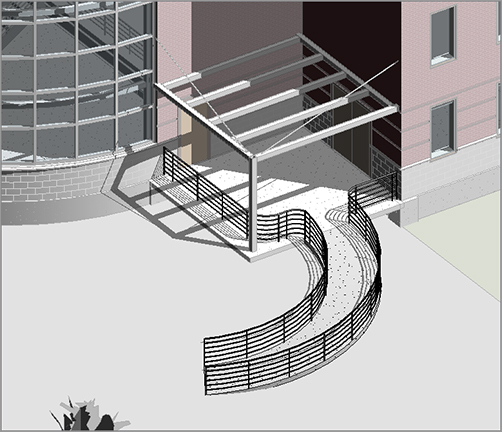
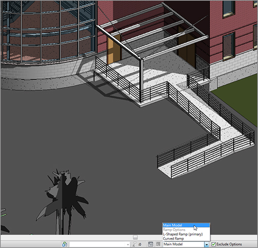
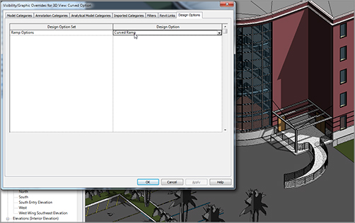
Of all the projects I have been involved with over the years, I can remember only a handful that didn’t involve some kind of existing condition. It would be nice if we could find a giant, flat field on which to construct our buildings, but those projects are few and far between. The term phasing in Revit is often taken literally and can be confused with construction sequencing. When we talk about phasing in the context of how Revit views it, we’re talking about adding new construction to an existing building, and demolishing the existing structure. Although you can use Revit to track all aspects of construction, the base use and purpose of phasing is dealing with existing conditions. The first section of this chapter will focus on the setup of your phasing scheme. By default, Revit Architecture provides two phases: Existing and New Construction. As it stands, everything you’ve placed into your model for the last 20 chapters has been exclusively on the New Construction phase. You’ll now alter that. I’ve seen this scenario played out more times than I’d like. People get Revit, build a model, and then start clicking the Demolish button found on the Phasing panel on the Manage tab (see Figure 21.1). Yes, doing so forces hidden lines, and now you’re demolishing walls that were constructed in the same phase that they’re being removed. You can’t do that! With some practice, and by following the procedures in this chapter, you’ll be able to swing that hammer all you want. But for now, to get started, go to the book’s web page at www.sybex.com/go/revit2012ner. From there, you can browse to Chapter 21 and find the file called The objective of the following procedure is to create a Demolition phase and insert it between the Existing phase and the New Construction phase. Follow along: FIGURE 21.1 Clicking the Phases button FIGURE 21.2 Adding the Demolition phase FIGURE 21.3 Duplicating the view FIGURE 21.4 Changing the phase to Demolition FIGURE 21.5 Setting the demolition FIGURE 21.6 You no longer need these doors. After you’ve changed the phasing of an object’s creation and demolition, Revit magically puts everything on the correct display. Well, as magical as it seems, there are some features driving this display. Let’s take a look at them: FIGURE 21.7 The completed phasing Another function of Revit that we need to venture into is similar to phasing but has an entirely different meaning when it comes to tracking aspects of a project. This functionality is called design options. Revit is equipped with the functionality to allow you to model different options in one model, better known in the design world as bid alternates. The great thing about how Revit handles this functionality is that any alternate design is never (or at least, is seldom) a completely new structure. Some items are in more than one option. Revit lets you keep like items intact while creating new or different items that belong to different options. This creates a situation in which you only need to model the common items once, so you can focus on the alternates. FIGURE 21.8 Making the existing shading darker That being said, there is a lot to be added to this functionality in future versions of Revit. To start adding and implementing Design Options, follow the preceding steps. FIGURE 21.9 Clicking the Design Options button FIGURE 21.10 Adding options FIGURE 21.11 Adding to a set It’s time to create a new ramp. To do so, follow along: FIGURE 21.12 Jumping into an option FIGURE 21.13 The curved option FIGURE 21.14 Switching back to Main Model FIGURE 21.15 Setting the view’s default option As you can see, this is a powerful tool. Gone are the days of copying around several AutoCAD files to accomplish the task of designing alternates. The great thing about the design options in Revit is that if you need to make a modification to the building, and it needs to be shown in all your options, you can simply make the Main Model option current, and work away.
CHAPTER 21
Phasing and Design Options
Managing Project Phasing
NER-32.rvt. (If you prefer, you can follow along with your own model as well.)
![]() Duplicate View, as shown in Figure 21.3.
Duplicate View, as shown in Figure 21.3. 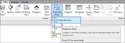
Examining Graphic Overrides
Creating Design Options
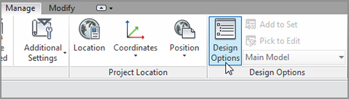

Are You Experienced?
Now you can…