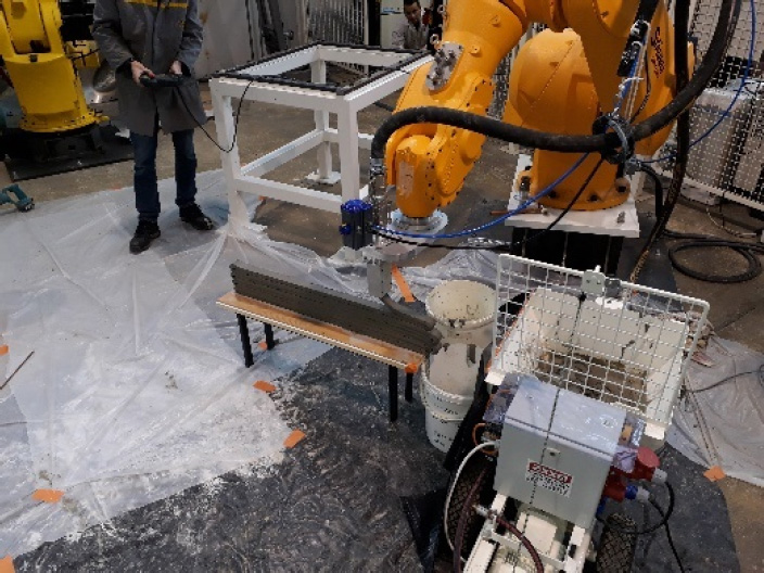
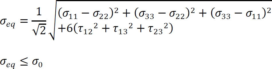
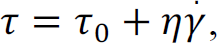
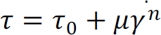
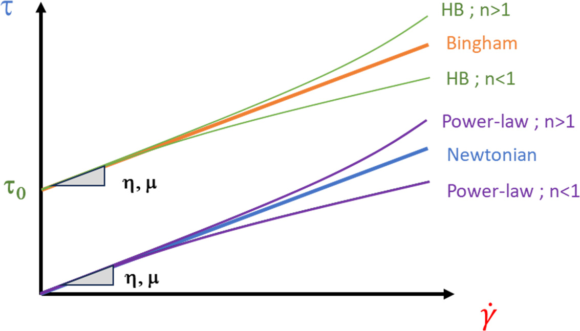
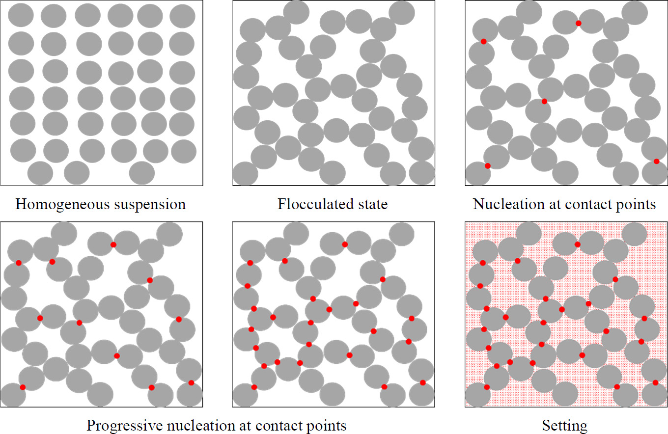
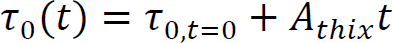
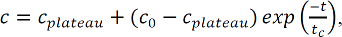
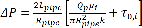
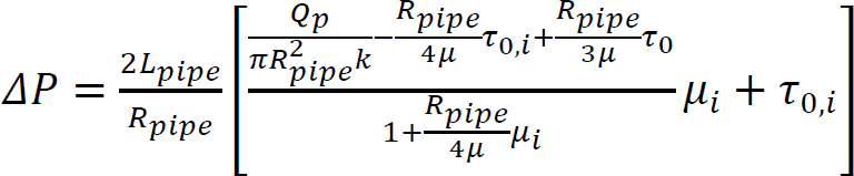
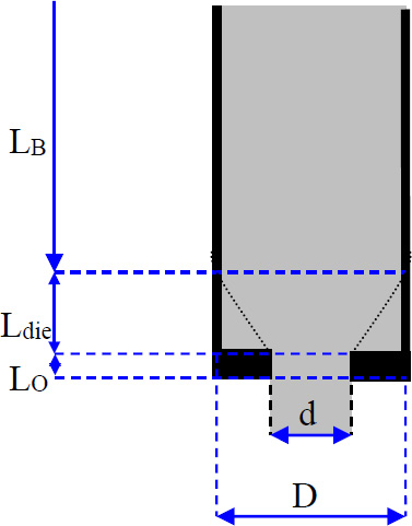
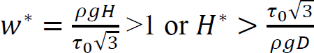
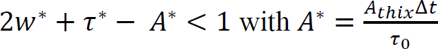
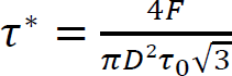
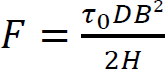
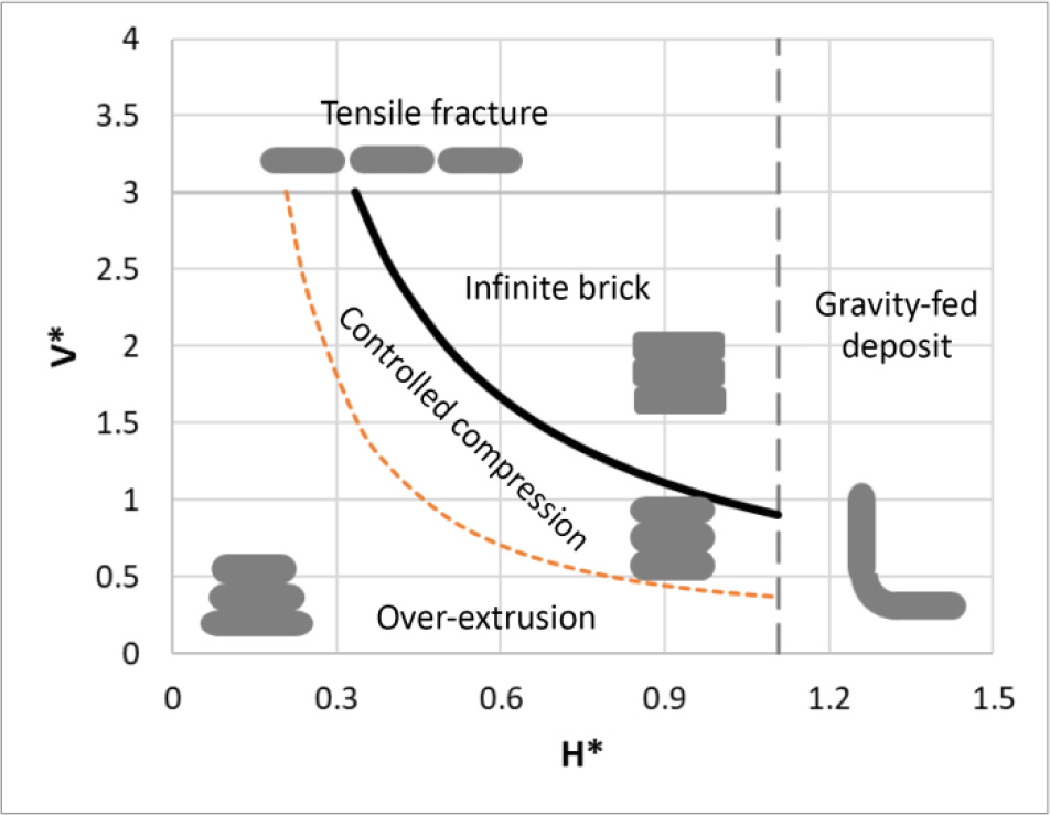
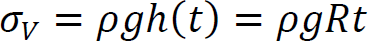
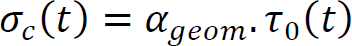
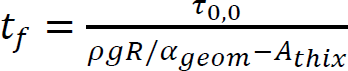
Arnaud PERROT1 and Yohan JACQUET2 1 IRDL, Université de Bretagne Sud, Lorient, France 2 Technische Universität Berlin, Germany Extrusion/deposition 3D printing is currently the most widely studied and most widespread process in concrete additive manufacturing (Wangler et al. 2016; Mechtcherine et al. 2020). This robotized manufacturing process can be broken down into a number of stages, from the manufacture of the material to the curing of the printed object to ensure good mechanical performance. This complex process includes conveying the material to the print head, often by pumping, shaping it by extruding a filament material, then depositing it in successive layers to form a stable structure (Perrot et al. 2016, p. 201; Roussel 2018; Wolfs et al. 2018). For each of these steps, the fresh cementitious materials must exhibit adequate rheological behavior to enable them to move on to the next step. In particular, the material must be able to flow to the printing nozzle and must be able to maintain a shape after deposition to ensure the stability of the structure during printing. Generally speaking, in the laboratory or on site, a print head attached to a robotized system deposits the fed material, layer by layer, following a programmed trajectory to form the structure to be printed (Figure 2.1). Depending on the application and the form to be printed, there is a wide variety of extrusion-deposition printing methods. These differ in terms of delivery method, type of formulation (single-component or two-component with the addition of a structuring/flocculating agent or hydration accelerator at the printhead) (Mechtcherine et al. 2020; Perrot et al. 2021; Wangler et al. 2022) and the robotic system used. For the last category, various technical solutions can move the print head, such as gantries or overhead cranes (Khoshnevis 2004), fixed articulated arms (Gaudillière et al. 2020) or mounted on rails or mobile machinery (Khoshnevis et al. 2005; Leach et al. 2012), delta robots (Asprone et al. 2018), or supports or even traditional lifting means diverted from their original purpose (Schack et al. 2017; Nerella and Mechtcherine 2019). This diversity of robotic solutions and printable materials makes it possible to build on a variety of scales from small prefabricated elements to entire buildings (Souza et al. 2020; Xiao et al. 2021). To understand the 3D concrete printing process by extrusion-deposition, we must be familiar with the behavior of the material in its fresh state. This will enable us to understand each stage of the printing process and the constraints imposed on the material by the printing process. Figure 2.1. 3D printing of mortar by extrusion and filament deposition using a pump and a six-axis robotic arm. In this chapter, the diversity of extrusion-deposition printing processes will be presented to provide a comprehensive overview of the range of possibilities. We will then focus on cementitious materials in their fresh state to understand their behavior during each stage of the printing process, from mixing the materials to the evolution of the printed structure during the first hours and days after printing. The size of the printed structure has a direct impact not only on the means of printing, but also on the properties of the material to be printed. Printing small parts, for example, of the order of a few tens of centimeters in height, implies a limited load on the fresh material during printing and therefore does not necessarily require the cementitious material to harden rapidly for the structure to remain stable. In fact, the weight acting on the base layer depends directly on the number of layers stacked and the height of the printed form. This printing situation is the simplest from a material point of view, as it is compatible with common mortars and concretes. On the other hand, a prefabricated part such as a lost column formwork (around 3-meters high for a standard building level height) will induce a load of around 70 kPa (a hydrostatic-type load equal to the product of density, printed height and acceleration of gravity). What is more, the length of the bead to be printed for one layer is small, and the rate of rise of the structure can be very rapid (of the order of 10 cm or more per minute). Traditional cementitious material will not be able to withstand the induced loading and ensure the stability of the structure. It is therefore necessary to accelerate the curing rate of the cementitious binder to guarantee successful printing. Formulating a material with texturizing agents or setting accelerators is therefore necessary in this case. A third printing situation is the automated manufacture of entire buildings. In this case, the bead length of a layer can be several tens of meters, and the speed at which the structure rises during printing is fairly low. In this case, the formulation of the material to be printed does not necessarily require high curing speeds to ensure that the structure remains stable during printing. On the contrary, too fast a curing speed could be detrimental to good inter-layer bonding, and therefore to the mechanical strength of the printed structure once cured. It is important to be able to guarantee the robustness of the material concerning exposure to the external environment between two successive deposits. This can be achieved by adding additives to protect the material from over-drying or leaching when exposed to rain. A comparison of these three situations shows that the application, and particularly the size of the printed element, has major repercussions on the formulation of the printed cementitious material and its characteristics in the fresh state (in particular its setting speed). In order to guarantee the success of the printing process in relation to the intended application, it is therefore possible to influence not only the formulation of the material, but also the robotic solution used. When it comes to materials used in 3D printing by extrusion and filament deposition, there are two strategies based on their formulation. The first material solution is known as single component and is based on the formulation of a cementitious material that can be pumped to the print head and has a structural build-up speed adapted to the printed form. This method has the advantage of being relatively simple from a technical point of view, as the cementitious material undergoes no change between the end of the mixing operation and the deposition. However, this method requires extreme precision in terms of print sequencing, as the age of the material is directly related to its strength level. Thus, any pause in the process can induce a delay leading to hardening of the material before it is deposited either in the tank or in the pipes of the concrete pump. In extreme cases, this can lead to pump blockage and printing stoppage. This lack of process robustness becomes more significant the higher the structural build-up speed. Single-component materials are therefore particularly suitable for printing situations where the required structural build-up rate remains limited. However, it is worth noting that some applications requiring rapid structural build-up speeds can be achieved with single-component materials, as shown by Weber beamix or Vertico, for example, but this requires mastery of the material and the process, as well as considerable technical expertise. The second solution involves mixing two materials at the print head, transforming a pumpable material with stable rheology over time into a rapidly hardening material. This formulation strategy increases the robustness of the process with regard to the pumping stage (little risk of material hardening in the pipe), but requires the choice and dosage of a texturizing agent or setting accelerator to achieve a high structuring speed, and the design of an active or passive system for injecting this agent and mixing to achieve a homogeneous material (Reiter et al. 2020; Wangler et al. 2022). This formulation stage can be tricky because hydration kinetics are highly dependent on the quality and composition of the raw materials. The design of the injection and mixing process can therefore be complex and also requires dimensioning the size of the mixing zone, the active or passive mixing system, and ensuring sufficient residence time to obtain adequate mixing (Wangler et al. 2020). Traditionally, for this so-called two-component process, the cementitious material is pumped and a small quantity of accelerator is added at the print head. Recently, a dual pumping system where the accelerator mixed with an inert suspension (sand and fine limestone) is pumped in parallel with an equivalent quantity of cementitious material before the materials are mixed at the printhead (Tao et al. 2022). This method allows for good control of accelerator dosage and delivers excellent results. Two-component materials are particularly well-suited to the 3D printing of slender prefabricated parts or parts with cantilevers that need to be strengthened very quickly and are frequently used by prefabricators of printed parts. The complexity of the robot and the number of its degrees of freedom will have a direct impact on the extrusion-deposition printing process. The simplest three-degree-of-freedom robots (Cartesian robots) generally feature a cylindrical cross-section printing nozzle, resulting in a surface structure with strands. The addition of a degree of freedom, rotation around the vertical axis, makes it possible to print with a rectangular-section nozzle, producing a printed structure with a potentially smooth, bulge-free surface. In this case, the robot’s trajectory must be programmed so that the printhead cross-section remains perpendicular to the robot’s direction of travel. Finally, the use of a six-axis robot means that complex trajectories can be achieved with a vertically oriented print head, enabling cantilevered structures to be produced. The progressive orientation of the print head as the structure is printed and raised allows the shear strength of the interfaces to be mobilized for local and global stability during printing. This robotic solution, more complex from a trajectory generation point of view, is therefore to be preferred when printing complex structures (Gosselin et al. 2016; Carneau et al. 2020). It should be noted that some authors have drawn inspiration from traditional masonry techniques for the manufacture of vaults and domes, utilizing six-axis robots in a concrete 3D printing context (Carneau et al. 2020). Cementitious materials are yield stress materials (Tattersall 1976; Tattersall and Banfill 1983). This means that the material only begins to flow when subjected to a stress above a critical value known as the plastic yield stress. This threshold value depends on the type of loading and differs in shear, elongation (induced by a difference in axial stresses) or combined (shear + elongation) flow. Below this critical value, it is often assumed that cementitious materials behave as elastic solids (Roussel 2018; Mechtcherine et al. 2020), although the material behavior has a viscous component (Esposito et al. 2021). It is important to note that it is on this duality of behavior that the possibility of printing a cementitious material rests: it is necessary to impose a stress greater than the yield stress to convey the material to its deposition and then ensure that the stresses acting on the structure during printing remain below the material’s flow yield stress (Perrot et al. 2016). The elastic deformations of the loaded material must also be controlled below its shear yield stress to ensure good shape control and avoid buckling of the structure (Wolfs et al. 2018). To facilitate printing, it is important to note that we can take advantage of the rigidification of the material linked to the chemical activity of the cement to increase the plastic yield stress and rigidity of the deposited layers (Roussel 2006, 2018). When printing mortar or concrete, the material must, depending on the stage, exhibit either solid behavior to hold its shape (after deposition) or liquid behavior to flow and be conveyed (during pumping and extrusion). It is therefore essential to understand the transition between the liquid and solid behavior of the material. This transition is a decisive characteristic of fresh concrete for printing purposes. The so-called static yield stress, which is a stress that occurs at a critical deformation called εc in elongation or γc in shear. This flow or plasticity yield stress is τ0 for shear flow and σ0 for elongation flow. For complex loads, before the cement paste or mortar sets, a Von Mises plasticity criterion can be used (Mettler et al. 2016) to check whether the material will behave as an elastic solid (criterion not met) or as a fluid (criterion met). This criterion is written in the following form: Here, σii and τij are the components of the stress tensor, σeq is the equivalent Von Mises stress and σ0 is the value of the plastic yield stress. Other criteria can be used, such as the Tresca criterion, although the Von Mises criterion is more widely used for cementitious materials in the fresh state (Adams et al. 1997; Ovarlez and Roussel 2006; Perrot et al. 2012). For unconfined compressive loading along axis 1, as in a vertically printed layer, the Von Mises criterion becomes: It should be noted that the use of these criteria makes it possible to determine a link between the shear yield stress and the elongation yield stress. Thus, for the Von Mises criterion in simple shear (axes 1 and 2), we can write: This load is representative of what happens when the material is flowing in a pipe. τ0 is also known as the (static) shear yield stress. This is the shear yield stress that is traditionally used in many concrete-related manufacturing processes to qualify consistency and suitability for use. This static shear yield stress is representative of the state of structural build-up of the material’s microstructure, which develops resistance over time. For formulations containing a high solid fraction close to the maximum compactness of the granular mix, the material’s behavior becomes more complex and pressure-sensitive (Mettler et al. 2016; Wolfs et al. 2019; Jacquet et al. 2021a). In this case, soil mechanics models such as the Coulomb or Drucker–Prager criteria can be used to determine material flow and the onset of plastic deformation (Khelifi et al. 2013). Coulomb’s model uses an internal angle of friction to account for the material’s resistance to inter-grain friction. Finally, we must bear in mind the multiphase nature of cementitious materials and the possible phase separations that may occur during the different phases of the process in order to take advantage of them or to avoid possible inconveniences (Khelifi et al. 2013; Perrot and Rangeard 2016; Massoussi et al. 2017). Under steady-state flow conditions, cementitious materials flow as a quasi-Newtonian viscous fluid (viscosity η) or as a power-law fluid when subjected to a stress above the so-called dynamic yield stress τ0 (Roussel 2005; Roussel et al. 2010). This type of behavior can be described by a Bingham model written as equation [2.4] or by the Herschel–Bulkley model written as equation [2.5] for shear stress (as traditionally written in the literature): Here, γ̇ is the shear rate, τ is the shear stress, μ is the consistency for the Herschel–Bulkley model and n is the flow index. The value of n controls the decrease or increase in apparent viscosity with increasing shear stress. The behavior is said to be shear-thinning for n < 1 or shear-thickening if n > 1, as illustrated in Figure 2.5. Figure 2.2. Shear stress–shear rate relationship for a Bingham fluid (dashed linear relationship) and two Herschel–Bulkley (HB) fluids with flow indices n less than and greater than 1. Models describing the flow behavior of cementitious materials are useful for simulating the flows involved in pumping and extruding cementitious materials when the flow is steady state and the material’s microstructure does not change due to colloidal interactions or the chemical setting of the cement. In this case, the cement grain network is said to be destructured and the flow is said to be steady state. Under yield stress loading, such as the loading acting on a layer of material deposited during printing, it is commonly accepted that cementitious materials behave as linear elastic solids exhibiting an elastic modulus E in compression and G in shear. This modeling is undoubtedly too simplistic, as behavior below the shear yield stress is clearly nonlinear (Roussel et al. 2019). Also, deformations are not fully reversible due to a viscous component in the material’s behavior below the shear yield stress (Esposito et al. 2021). However, the use of a linear model describing the material’s apparent behavior is sufficient to describe the material’s behavior in a printing situation (Wolfs et al. 2018; Suiker et al. 2020). This elastic behavior is therefore important for calculating the deformations of printed structures under their own weight. The critical elastic deformation is often used to define the limit of the elastic domain. This deformation is written εc in compression/tension or γc in shear. The ratio between the yield stresses, in compression and shear, and the corresponding critical deformations is used to define the corresponding apparent elastic stiffness moduli E = σ0/εc in compression and G = τ0/γc in shear (Roussel et al. 2010; Roussel 2018). Once in contact with water, cement undergoes a temporal evolution that changes its physical and rheological characteristics, as well as the structure of the suspensions. It is this progressive modification of the microstructure linked to cement reactivity that results in an increase in the material’s strength and rigidity, which is mobilized to enable the structure being printed to remain stable. In fact, unlike plastics, the material’s behavior cannot be considered thermo-dependent, and the rigidification of the material is not due to cooling. Matching the kinetics of mechanical structural build-up of the material linked to the activity of cement in water to the printing rate is therefore crucial to the success of printing (Wangler et al. 2016; Perrot and Rangeard 2016). To explain this rigidification, we need to take into account the organization of the network of cement grains suspended in water, as shown in Figure 2.3, which illustrates the different phases in the evolution of the microstructure. After intense mixing inducing destructuring, cement grains begin to flocculate under the influence of colloidal interactions. This flocculation into a structured network stiffens and strengthens the cementitious material on timescales of tens of seconds (Roussel et al. 2012; Roussel 2018; Kruger et al. 2019). In a second phase, the rapid formation of CSH bridges in the contact zones between the grains is responsible for further mechanical structural build-up of the resting cementitious material. This phenomenon of cement grain nucleation occurs during the first few minutes or even tens of minutes after water-cement contact, before setting during the so-called dormant period (Sleiman et al. 2010). Hydrates formation is chemically irreversible, but bridges between grains can be physically broken if the pumping and/or mixing system is sufficiently powerful. A true loss of workability (irreversible change in behavior) is achieved when the rate of hydrate formation becomes too rapid (Mantellato et al. 2019). Figure 2.3. Evolution of the microstructure of a cement suspension at rest. Large circles represent cement grains, small circles hydrates. These microstructural changes result in an increase in the material’s behavioral parameters with increasing dwell time. To study the various stages of the printing process, researchers often use the evolution of stiffness and shear yield stress. The evolution of the material’s shear yield stress at rest is the most widely used indicator to describe the evolution of microstructure on mechanical behavior. The first way of modeling the increase in the shear yield stress with time is a linear model that defines an Athix structural build-up rate in Pa·s–1 over a given period (Roussel 2005, 2006). In this case, the equation is written as follows: Here, τ0,t=0 is the material’s shear yield stress in the destructured state and t is the duration of the material’s rest period. In this case, it is possible to define a characteristic structural build-up time t2x, which corresponds to the time required to double the material’s yield stress. This characteristic time is: Linear modeling of the shear yield stress is generally valid over a given resting period of the cementitious material (Subramaniam and Wang 2010) of a few tens of minutes for conventional non-accelerated cements. Beyond this, the increase in strength accelerates and the structural build-up kinetics become exponential (Perrot et al. 2015; Lecompte and Perrot 2017). This change in rate can be explained by an increase in the rate of formation of hydrates that interact with each other. Perrot et al. (2015) proposed an exponential shear yield stress evolution law that tends toward the linear model for short times. This model is written as: Here, tc is a characteristic time for which the behavior can be considered linear. Figure 2.4 shows that the model in equation [2.8] can be used to describe the evolution of the shear yield stress over longer periods than the linear model. However, as explained above, the evolution of the shear yield stress is due to at least two phenomena: the flocculation of colloidal particles and the creation of hydrates, which create new interactions and then increase the solid volume fraction in the material. As a result, Kruger et al. (2019) have developed a bilinear model that dissociates these two phenomena by defining two characteristic velocities, a flocculation velocity Rthix and a cement grain nucleation velocity Athix. The model is written as: The bilinear model provides a good description of the evolution of the shear yield stress in the first instants when the flocculation phenomenon has not ended. As proposed by Nicolas et al. (2022), it is possible to combine the Perrot and Kruger models to obtain a more accurate description of the evolution of the shear yield stress over longer periods. There are other, more sophisticated models to describe the evolution of the shear yield stress over time (Mettler et al. 2016; Lecompte and Perrot 2017; Wolfs et al. 2019). The creation of new hydrates during the material’s resting period induces a change in the type of behavior of the cementitious material, which becomes increasingly granular and then brittle solid. Figure 2.4. Example of applications of models describing the evolution of the shear yield stress of a mortar at rest. The solid line corresponds to the exponential model, the dashed line to the bilinear model, the dotted line to the linear model and the dots to the experimental measurements. Some authors have thus demonstrated that the Von Mises-type plasticity criterion is no longer adequate to describe material failure. Mechanical behavior thus shows a progressive tension/compression asymmetry, leading to brittle behavior typical of concrete with tensile weakness (Jacquet et al. 2021b). In this case, a Coulomb-type plasticity criterion is used to model the pressure-sensitive failure of the material. In terms of material stiffness and pseudo-elastic deformation, the critical strain decreases slightly as the material stiffens (Mettler et al. 2016; Roussel 2018). This increase in stiffness over time translates into an increase in elastic modulus. These increases in stiffness and strength enable the deposited material to withstand the increased loads associated with printing the structure. In this way, it is possible to calculate and predict the optimum manufacturing speeds to guarantee the structure’s stability and ensure compensation for elastic deformation, as we shall see in the following sections. The behavior of cementitious materials in the fresh state, with both solid and evolving behavior at rest and fluid behavior above a certain level of stress, makes it possible to consider material printing. At each stage of the printing process, the material behavior will be specified (Mechtcherine et al. 2020). In the next section, the various stages of the printing process will be presented and described in order to understand the material parameters involved and to move toward a specification of characteristics. When 3D printing elements in cementitious materials, mixing is a crucial stage to ensure that the material has the expected properties, both in its fresh and hardened state. Indeed, mixing energy has a direct influence on the hardened properties of concrete, particularly when numerous admixtures are used, which need to be well dispersed in the material to make the mixture homogeneous (Dils et al. 2012). Monitoring the power consumed by the mixer, and the appearance of a consumption plateau, is a sign of efficient mixing and that the mixture has become homogeneous (Chopin et al. 2004). However, it should be noted that power consumption data are often very irregular and can be difficult to interpret. The use of tracers or colorimetric analysis can prove effective in ensuring material homogeneity. For example, Jézéquel and Collin (2007) have shown that the colorimetric index of tracer particles tends toward a plateau value following exponential kinetics. where cplateau is the final colorimetric index, c0 is the initial value and tc is the characteristic dispersion time. It should be noted that the characteristic time takes into account the various mechanisms involved in mixing. This characteristic time depends on the speed of the mixer and the rheology of the material and varies between 1 and 10 minutes (Jézéquel and Collin 2007). For 3D printing applications, it has been demonstrated that intense mixing under a high shear gradient can generate cement grain crushing, which creates colloidal nanoparticles that promote the material’s mechanical structural build-up speed and binder reactivity (Vandenberg et al. 2019). This method, which requires fine control of the process, has yet to be adapted to industrial scale. Finally, in two-component printing systems, a mixing system is needed to inject a “hardener” additive for rapid printing (Marchon et al. 2018). This hardener, perhaps a setting accelerator, a fast-setting binder or a colloidal agent, promotes the formation of a solid flocculated network. In such a printhead, the quality of the mixture will depend on the residence time of the material, which can vary from one to several tens of seconds (Wangler et al. 2020). The use of a static or dynamic in-line mixing system is necessary to ensure material homogeneity. This mixer must be able to create sheared layers spaced by a length smaller than the characteristic diffusion length of the material during its residence time in the print head, which is below 100 µm (Mechtcherine et al. 2020; Perrot et al. 2021). Recent studies present a state of the art of printhead and in-line mixer technologies and highlight the need for prediction and control of the quality of the mix achieved (Chen et al. 2023). Pumping is a classic step in the manufacturing process for concrete and other cementitious mixes. Large-scale on-site pumping with printable concretes is not yet a common problem, but most printing processes use a pump to convey the material over distances of around ten meters or so. However, pumpability over medium distances is a prerequisite for many printing projects, even in the factory. The pumpability of concrete depends on materials and processing parameters, and it is generally described by pressure–flow relationships (Kaplan et al. 2005; De Schutter and Feys 2016; Feys et al. 2022). It is therefore necessary to adapt the power and pumping system to the formulation used. For example, the diameter of the aggregates must be well suited to the operation of the pressurization system and to the diameter of the pipes to prevent blockage. Similarly, the dosage of aggregates should be limited so as not to give the cementitious material a predominantly frictional character that could lead to flow stoppage. Pipe flow in a viscoplastic material such as concrete is characterized by a shear velocity gradient that decreases with distance from the pipe wall, and an unsheared zone in the center of the pipe. This is because the shear stress in this zone is below the material’s τ0 shear yield stress. However, during pumping, a phenomenon of particle migration under shear induces a movement of particles toward the less sheared zones (in the center of the pipe) and generates the formation of a lubrication layer composed mainly of cement paste and the finest sand grains (Secrieru et al. 2018; Tavangar et al. 2022). This phenomenon must be taken into account when predicting pumping pressure and flow rate, and it facilitates the flow of cementitious material. The behavior of the material in the pipe is then dictated by these wall effects and the rheological characteristics of this lubrication layer, which has a shear yield stress τ0i and a viscosity μi lower than the values of the initial material. Kaplan’s (1999) work has made it possible to construct relationships between pumping flow and pressure for cementitious materials with this lubrication layer. The pressure ∆P and flow rate Qp are linked by equations using the parameters of the Bingham model of the concrete and lubrication layer, and the geometry of the pumping pipe (length Lpipe and radius Rpipe). Equation [2.11] is applicable in the case of a flow where only the lubrication layer is sheared. The adjustment coefficient k can be obtained by means of tribological measurements (Kaplan et al. 2005; Kwon et al. 2016). Equation [2.12] covers the case of flow where shear occurs in the lubrication layer and within the concrete: Determining the rheological properties of the concrete and lubricating layer, as well as the thickness of the lubricating layer, is a difficult task that limits the applicability of the above models for predicting pumping pressures (Choi et al. 2014). In real cases, the use of numerical simulation tools may be necessary to properly account for particular geometries such as bends, narrowings or widenings of sections (De Schryver et al. 2021). Extrusion is the last phase in the pre-deposition routing of the cementitious material filament. Passage through the printhead die corresponds to the extrusion phase and gives the bead its shape before deposition (Perrot et al. 2019). Extrusion will therefore induce a narrowing of the material filament cross-section, necessitating an increase in the pumping pressure required to ensure material flow in the printing system. In the filament deposition/extrusion printing process, extrusion occurs as a continuation of pumping. As in the pump lines, the advancement of the material through the extruder is often influenced by the formation of a lubrication boundary layer where shear is concentrated (Khelifi et al. 2013). This condition generates a so-called plug flow, in which the material is only sheared very locally at the interface. Extrusion flow can be broken down by a flow description into three distinct parts (Perrot et al. 2012) (Figure 2.5): This zonal decomposition allows us to write the extrusion force as the sum of two contributions relative to the different parts of the flow: Figure 2.5. Decomposition of extrusion flow–axisymmetric case. D is the diameter of the piston, d is the diameter of the die, Ldie is the length of the conical zone, L0 is the length of the final pipe and LB is the length of the plug flow zone. Some studies suggest that extrusion pressure is proportional to the material’s shear yield stress (Perrot et al. 2012; Zhou et al. 2013). The extrusion stage can induce specific problems such as aggregate blocking (El Cheikh et al. 2017) or material consolidation in the constriction (Perrot et al. 2007). These problems are linked to the size and volume fraction of the largest aggregates, which can impart granular-like behavior to the material. It is therefore advisable to select the size of the largest aggregates in the composition according to the size of the die and not to exceed a critical volume fraction of aggregates (around 80% of the maximum compactness of the aggregate mix) to maintain viscoplastic behavior (Yammine et al. 2008). Regarding the consolidation phenomenon, during the extrusion of cementitious materials, there is competition between the kinetics of interstitial fluid drainage influenced by the pressure gradient in the die, and the speed of material advancement during extrusion (Toutou et al. 2005; Perrot et al. 2009, 2014; Khelifi et al. 2013). The appearance of drainage will increase the material’s frictional behavior, heighten the risk of defects and induce a rise in pumping pressure. To counter this phenomenon, printable cementitious materials often contain a viscosifying agent to slow down drainage kinetics by increasing the viscosity of the interstitial fluid, thereby preventing this consolidation phenomenon (Varela et al. 2023). Managing the deposition of material filaments to form structure layers is one of the crucial points in defining the printing process. Indeed, the deposition strategy will influence the choice and complexity of the robot, the surface finish of the printed structure and also its mechanical characteristics in the hardened state (Duballet et al. 2017). Several deposition methods have been developed since the early days of extrusion-based 3D concrete printing. Historically, the first developments of this process at Loughborough University or in Southern California with Professor Koshnevis’ team followed diametrically opposed solutions. The Loughborough University team (Le et al. 2012; Lim et al. 2012) chose to deposit small millimetric filaments of cylindrical cross-section that deform under their own weight. The deformation of these cylinders fills the voids created by the shape of these filaments to create a compact structure. In this case, the final height of the filament is dictated by its shear yield stress. The material is subjected to gravity, which induces a vertical stress at the base of the filament equal to ρg∆h with ρ the density of the material and ∆h the height of an elementary layer. Equilibrium is reached when the stress generated becomes equal to the material’s elongational shear yield stress. In contrast, for processes such as Contour Crafting or ConPrint3D in Southern California (Khoshnevis 2004; Nerella and Mechtcherine 2019), the layers have a rectangular cross-section, which is intended to be that of the die. In this second case, the shear yield stress must be higher than the stress generated by gravity. These two cases can be considered to be asymptotic limits of possible deposition strategies. Indeed, the Loughborough process corresponds to a free deposition that is dictated solely by the effect of gravity on the filament leaving the printhead, whereas the contour crafting process uses the so-called “infinite brick” process, where the shape of the bead is influenced solely by extrusion and deformation of the bead in the die. It should be noted that free deposition of a material filament can generate regular filament patterns such as alternating loops or a repetition of translating loops that are due to local buckling of the material under its own weight. Geffrault’s work (2022; Geffrault et al. 2023) provides a theoretical framework for predicting the pattern of the deposited filament as a function of two scaled parameters: scaled height (ratio of printhead height to die diameter) and scaled speed (ratio of robot feed speed to filament exit speed). This analysis makes it possible to design complex multi-outlet dies that can produce an optimized wall structure in a single pass, without the need for additional mechanized systems (Geffrault 2022). In all cases, to manage the deposition process properly, it is necessary to adjust the extrudate exit speed to the printhead translation speed, so as not to generate tensile stress that could lead to filament breakage, or excessive compressive stress in the filament if the extrusion rate is too high (Carneau et al. 2022). Between these two processes, it is possible to imagine a whole range of deposition strategies where the shape of the deposited filament is influenced by both gravity and the shape and position of the die. One of the most widely used solutions is called controlled compression deposition, in which the die imposes a force perpendicular to the filament deposition plane and fixes the height of the deposited layer. The rheology of the material and its evolution over time, as well as the force imposed by the die, must ensure that the pressure exerted does not deform the support layers deposited underneath. In this work, Carneau et al. (2022) were able to theoretically describe the various controlled compression deposition processes by analyzing the deposition conditions in the same frame of reference as Geffrault et al. (2023) as a function of the geometric and kinematic parameters of the process and the rheological behavior of the cementitious material (Figure 2.10). Free deposition under gravity is observed when the gravity stress induced by a layer height equal to the deposition height (between the extrusion nozzle and the deposition surface) is greater than the material’s elongational shear yield stress. The material cannot support the load and flows under its own weight to an equilibrium height. It is important to note that this strategy can lead to poor control of the geometry of the printed structure, as the deformations of each layer can accumulate and result in significant print defects. Carneau uses the dimensionless weight w* to describe the occurrence of this deposition mode. Examination of the scaled velocity indicates whether tensile fractures will occur during deposition. The limit of this phenomenon, known as under-extrusion, can also be plotted on the (H*, V*) diagram. Finally, a comparison of the forces acting on the deposited layer should enable us to check whether the sum of the force exerted by the die is sufficient to deform the deposited layer, but not so great as to impact the layers deposited underneath. A first limit is established through a kinematic analysis: this upper limit for controlled compression of the layer depends on ensuring that the material has time to reach the support layer before the print head completely passes its position. This condition is written as follows in the dimensioned reference frame (H*,V*): H*.V* <1. The other limit is linked to the strength of the lower support layer, which receives the compressed layer deposited by the nozzle. This resistance also depends on the Athix structural build-up rate (the rate of increase in the shear yield stress in Pa/s of the material left at rest) of the cementitious material. Carneau et al. (2022) define a dimensionless structural build-up velocity A*, which is used to define the lower limit of the controlled deposition strategy in the (H*,V*) reference frame by balancing the forces on the deposition support layer (equation [2.14]). Here, ∆t represents the time between two consecutive deposits and τ* being the characteristic compressive stress of a layer, which can be written as follows: Carneau suggests using the compression work of a plastic fluid to write the compressive stress of a layer of material between two surfaces (Coussot 2005). The compressive stress of a layer can thus be written as: Here, B is the width of the deposited filament. The analysis proposed by Carneau allows us to predict the shape of the deposited filaments as a function of the geometric and kinematic parameters and the rheological behavior of the material, as shown in Figure 2.6. Figure 2.6. Cementitious material filament deposition strategies and situations in extrusion-deposition 3D printing from Carneau et al. (2022). Finally, in the case of cantilever structure printing using a three- or four-axis robot, it will be necessary to check that the deformation remains elastic for the part of the material not supported by an underlying layer (i.e. in the void). A check on the stability of the cantilever can be carried out to ensure that the material deflection at the end of the cantilever is not too great. This can be done by adopting a cantilever beam hypothesis, or by numerical simulation using finite elements, for example (Figure 2.11). The use of printed temporary supports is also an interesting alternative in this case, as in the case of fuse deposition modeling techniques for plastics. The issue of stability of a concrete structure during the manufacturing process is undoubtedly the most studied topic in the field of 3D printing by extrusion and filament deposition (Mechtcherine et al. 2020). Researchers have thus defined the ability of a cementitious material to support the weight of the structure being printed with the terms “buildability” or “printability” (Le et al. 2012), which translates the material’s ability to be printed and to support the weight of the layers deposited on top of it. The analysis of the problem identified two modes of failure for structures undergoing printing. The first mode is related to compressive failure of the base layer, which receives the heaviest loading (Perrot et al. 2016; Wangler et al. 2016). For this mode, failure occurs when the stress due to the weight of the printed layers exceeds the compressive elongational yield stress of the base layer material. This failure is the mode generally encountered for low-slung structural geometries (Roussel 2018). The second reported mode of failure is that associated with buckling of the printed structure linked to a lack of material rigidity (Wolfs et al. 2018; Suiker et al. 2020). This failure occurs when printing slender or complex structures with overhangs. Compressive failure of the base layer is a problem described by Perrot et al. (2016). This mode of failure occurs if the material’s compressive strength σ0(t) becomes less than the load acting on the first printed layer. This load is directly related to the weight deposited on the layer and therefore to the increasing height h(t) of the structure being printed. To describe the failure, we need to compare the temporal evolution of the mechanical strength of the cementitious material and the mechanical load due to the elevation of the printed form. The theory developed, on the one hand, indicates whether the layered structure is capable of supporting its own weight and, on the other, predicts when the structure will collapse due to the compressive failure of the first layer. In the case of the construction of a vertical wall or column, the vertical stress acting on the first layer deposited increases with time and with the elevation of the structure. In their work, Perrot et al. (2016) consider a constant average printing speed over the manufacturing time. This speed corresponds to the average vertical elevation speed of the structure and is denoted by R. It is important to note that the print elevation speed R depends on several factors such as the length of the contour to be printed Lc and the extruder feed speed Ve (Roussel 2018). In this case, the elevation speed depends on the geometry and can be written as R = VeH/Lc, where H is the thickness of a layer. The shorter the length of the contour to be printed, the faster the elevation speed. The elevation speed can then be used to write the evolution of the vertical stress σv acting on the first layer as a function of time and the density of the cementitious material ρ: The stability of the first layer and therefore of the structure can be assessed by comparing this vertical stress with the compressive strength of the material. This resistance, which according to Perrot et al. (2016), drawing on work on the squeeze test (Roussel and Lanos 2003), depends on the geometry of the printed layer, can be determined from the following relationship: where αgeom is a geometric factor depending on the cross-section of the deposited layers. Accurate estimation of material structural build-up over time to obtain the evolution of the shear yield stress over time τ0(t) (more commonly measured than the elongation one) is necessary to be able to compare the loading and strength of the first layer. In the simplest case, it is possible to use a constant Athix structural build-up rate, as proposed by Roussel et al. (2006). In this case, the stability of the structure is controlled by the Athix/R ratio, and it is possible to determine the instant of compressive failure of the first layer: However, the linear description of the evolution of the shear yield stress may prove too simplistic to predict the effective strength of the first layer. In their work, Perrot et al. (2016) showed that the use of expression [2.19] could lead to the calculation of an erroneous failure time when the shear yield stress does not follow a linear evolution. Also, the appearance of pressure-dependent behavior with a material presenting a nonzero angle of friction can favor the compressive strength of the first layer deposited. Another reported cause of structure failure during printing is related to elastic buckling of the structure. This mode of failure was initially described by researchers at the Technical University of Eindhoven (Wolfs et al. 2018). Figure 2.7 illustrates the buckling collapse of a printed square-section structure. This problem can be described theoretically by studying the self-weight buckling problem of a structure with a vertical elastic stiffness gradient (Suiker et al. 2020). This mode of failure will drive stability during the printing of slender, complex structures. In this case, in addition to the accuracy with which the layers are laid, which necessarily leads to eccentricities resulting in buckling instability, it is the evolution of the elastic modulus with rest time that will drive the instability of the structure under its own weight during printing. Figure 2.7. Structure undergoing buckling during printing The use of Euler’s buckling theory indicates that in the case of a strictly vertical element, the buckling limit height evolves with the cube root of the material’s elastic stiffness. Thus, considering a constant elastic modulus over the entire height of the structure, it is possible to propose the following relationship to calculate the critical height hc leading to buckling of the structure (Roussel 2018): with I the squared moment of the printed layer and A its cross-section in the horizontal plane. Equation [2.20] demonstrates the importance of layer design in minimizing the risk of buckling. A more precise analysis of the problem can be obtained by taking into account the elastic stiffness gradient along the height of the printed structure. An analytical development has been proposed by Suiker et al. (2020) to predict the buckling stability of vertical structures during printing. For more complex structures with cantilevers, numerical simulation is an appropriate solution to ensure stability during printing. However, it is important to select the right material behavior laws (and their temporal evolution) and accurately reproduce printing defects, which can often be sources of buckling initiation (Perrot et al. 2021). In addition to verifying the stability of the structure, we also need to ensure the fidelity of the print by checking the deformations of each layer under loading (each layer having, for a given time, its own rigidity due to different resting times). Depending on the type of deposition strategy chosen, the impact of elastic deformation is not the same: for free deposition under gravity, the deformations accumulate and can lead to a significant discrepancy between the expected height and the height obtained, or even to buckling during filament deposition. In contrast, with the controlled compression deposition strategy, each nozzle passage corrects these deformations, and the height of the structure is fixed by the passage of the printing nozzle. In the case of cumulative deformations, it is possible to estimate the elastic deformation of the first layer deposited during printing. Values of the initial elastic moduli of printed cementitious materials are of the order of 100 kPa (Perrot et al. 2016; Wolfs et al. 2018). In addition, elastic moduli evolve in the same way as shear yield stresses and it is possible to consider a linear evolution of the elastic modulus as proposed by Roussel. The resulting deformations can be non-negligible, demonstrating the need to take this phenomenon into account by ensuring sufficient stiffening speeds or reducing the elevation speed of the structure. During the impression of a curve, in a bend, the inside part of the bend is compressed, while the outside fiber is stretched. The risk of cracking increases as the radius of curvature decreases and the trajectory changes direction abruptly. The elongation undergone by the material can then be greater than the critical deformation of the material and create a crack that is detrimental to the aesthetics of the printed part, but above all, detrimental to the strength and durability of the hardened material (Perrot and Amziane 2019). This cracking is also detrimental for special applications such as underwater 3D printing (Mazhoud et al. 2019; Jacquet et al. 2021b). Solutions to increase resistance to cracking include the use of fibers or the addition of viscosity modifying agents. These solutions make it possible to increase tensile strength while increasing strain at failure. It will therefore be necessary to check that, when printing curved structures, the local radii of curvature do not generate deformation greater than the material’s critical deformation, which can be determined experimentally by console beam tests or tensile tests on fresh materials (Jacquet et al. 2020; Jacquet et al. 2021a). Unlike concrete in a formwork, printed structures are not protected at an early age and are therefore directly exposed to their environment. Interaction and exchange with the direct environment can lead to drying in dry weather, or even washout of the material during wet weather on site. During drying, the evaporation of water produces an exchange of a quantity of water toward the outside, the rate of which depends on the direct environment (temperature, humidity and wind speed). The water on the surface is the first to evaporate, creating a pressure gradient dominated by capillary pressure, which tends to transport water from the core of the material to the surface to rebalance the water content (Keita et al. 2019). This feed flow can be slowed down by reducing the permeability of the granular skeleton (grain size reduction) or by increasing the viscosity of the pore fluid (addition of viscosity modifying agents). The use of curing products or blankets is also a solution for reducing exchanges with the outside world, bringing the situation closer to that of formwork concrete. These precautions are important, as drying can lead to deleterious phenomena: significant dimensional shrinkage, lack of water for the hydration reaction, surface cracking and spalling. Taking into account the direct environment (temperature, wind speed, etc.) is therefore essential (in the same way as for the casting of large-area slabs) to take into account any drying that may be detrimental to the mechanical quality of the printed structure. One of the most frequently reported shortcomings of concrete 3D printing by extrusion and filament deposition concerns interface quality and interlayer bonding. Indeed, an interface between layers of good mechanical quality will confer good resistance to the material once hardened. Several solutions have been proposed in the literature to achieve this. The first is based on work on multi-layer casting in self-placing concretes (Roussel and Cussigh 2008; Wangler et al. 2016) and consists in forcing a mixture of the material in the two layers by attempting to destructure the material in the underlying layer. A second solution is to avoid or limit drying of the layer already deposited, as shown by the work of Keita et al. (2019). For example, the use of super-absorbent polymers (Nerella et al. 2017) and viscosity modifying agents is recommended to reduce the material’s permeability and/or susceptibility to drying. Drying can also be reduced by wetting the underlying layer before deposition, which has been shown to have a positive effect on the mechanical behavior of printed structures (Sanjayan et al. 2018). The third solution involves adding transverse reinforcements at the interfaces (such as nails, screws or staples) (Hass and Bos 2020; Perrot et al. 2020) or a bonding agent to ensure good mechanical properties of the interlayer and avoid possible delamination. Finally, it is possible to increase the contact surface between layers by creating grooves or striation on the surface of the layers. In this way, the underside of the deposited layer becomes embedded in the pattern of the support layer, increasing the contact area and hence the mechanical strength of the interface. Indeed, the greater the surface area of the layers in contact, the greater the strength of the interface (Van Der Putten et al. 2019). In all cases, the quality of the interface is crucial to the mechanical behavior of the printed material. It is important to note that good surface quality will result in a homogeneous material behaving like a monolithic structure, whereas poor quality will result in a laminated material sensitive to delamination. In all cases, it is often necessary to limit the time between deposits with a maximum value tmax to guarantee a good quality interface by reducing drying and facilitating mixing. In this chapter, we presented various methods of 3D printing by extrusion and filament deposition, highlighting the diversity of situations and applications reported in the literature and used by the construction industry. After presenting the fresh-state behavior of cementitious materials, in flow and at rest, we linked the main stages of the extrusion printing process by describing the behavioral parameters involved. While rheological behavior is involved in material transport and shaping, resting behavior (after strand deposition), characterized by hardening and stiffening kinetics, will limit the speed of the process to ensure the overall stability of the structure throughout printing. Also, the precision of placement and the elastic modulus of the material play a part in buckling stability and the feasibility of cantilever printing. Finally, we emphasized the importance of curing the material after printing to limit water exchange and guarantee optimum mechanical performance in the hardened state.
2
3D Concrete Printing by Extrusion and Filament Deposition
2.1. Introduction
2.2. Major printing families
2.2.1. A matter of scale
2.2.2. Single- and two-component materials
2.2.3. Robotic complexity
2.3. Printable materials
2.3.1. Material behavior during printing
2.3.2. Material flow behavior
2.3.3. Material behavior at rest
2.3.3.1. Elastic deformation below the yield stress
2.3.3.2. Evolution of material structure at rest

2.3.4. Printing specifications
2.4. The main stages in 3D extrusion printing
2.4.1. Mixing
2.4.2. Pumping
2.4.3. Extrusion
2.4.4. Filament deposition and local stability
2.4.5. Overall structure stability during printing
2.4.5.1. Fracture mechanisms of printed structures
2.4.5.2. Compression failure of the base layer
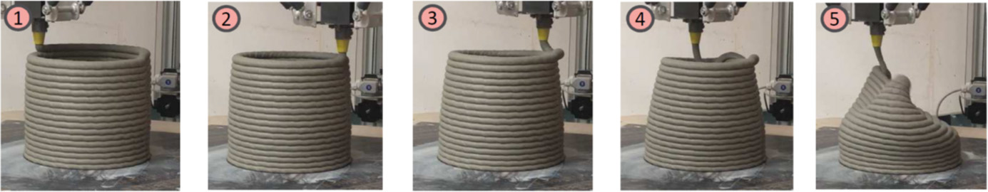
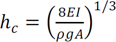
2.4.5.3. Buckling failure
2.4.6. Elastic deformation and printing precision
2.4.7. Material curing during and after printing
2.4.7.1. Tensile fracture cracking
2.4.7.2. Drying and induced shrinkage
2.4.7.3. Bonding between layers – weakness at the interface between layers
2.5. Conclusion
2.6. References
Note
3D Concrete Printing by Extrusion and Filament Deposition
[2.1]
[2.2]
[2.3]
[2.4]
[2.5]
[2.6]
[2.7]
[2.8]
[2.9]
[2.10]
[2.11]
[2.12]
[2.13]
[2.14]
[2.15]
[2.16]
[2.17]
[2.18]
[2.19]
[2.20]