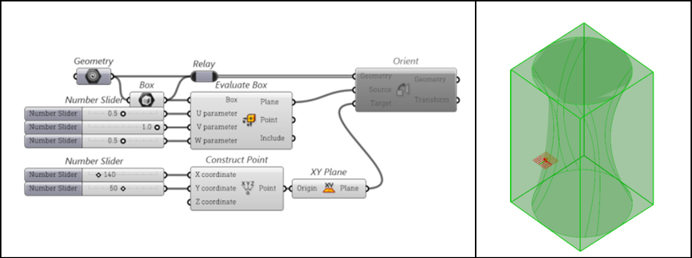
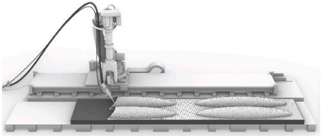
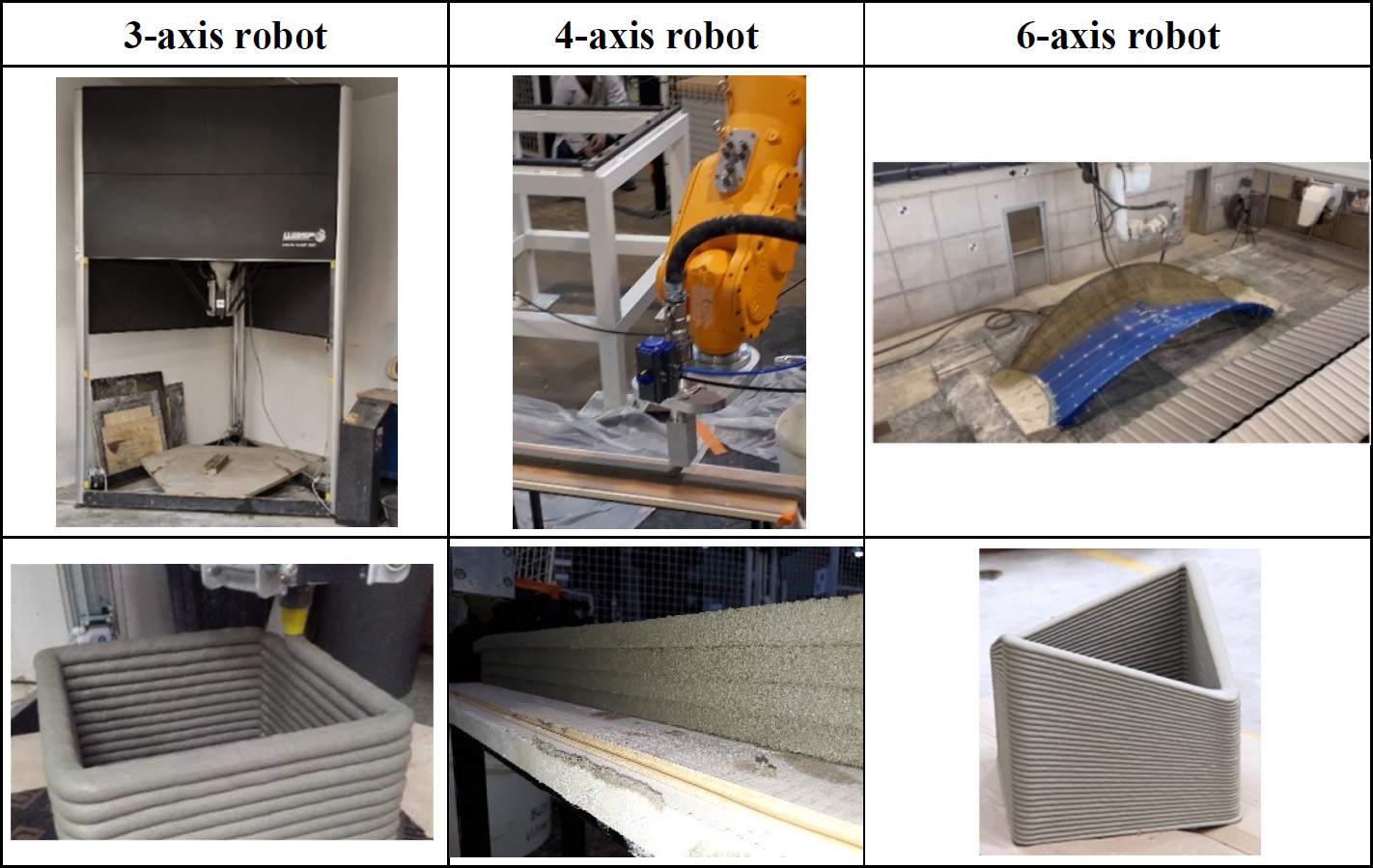
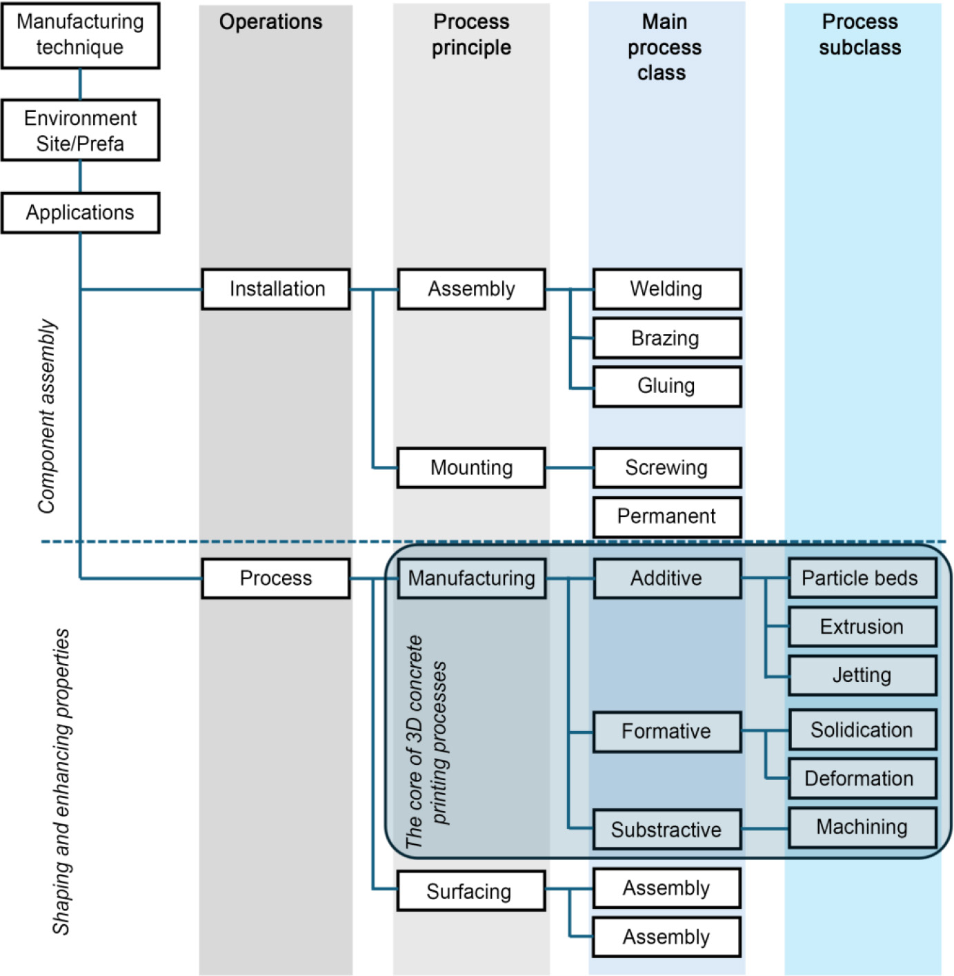
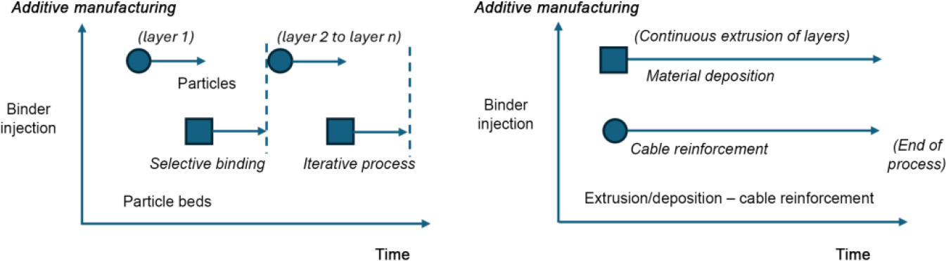
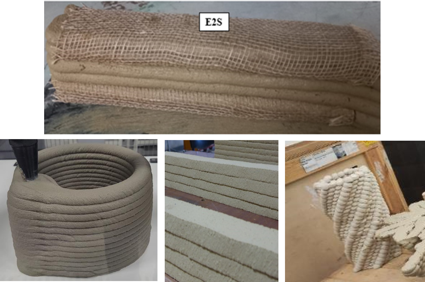
Arnaud PERROT1, Yohan JACQUET2 and Sofiane AMZIANE3 1 IRDL, Université de Bretagne Sud, Lorient, France 2 Technische Universität Berlin, Germany 3 Institut Pascal, Université Clermont-Auvergne, Clermont-Ferrand, France Since its initial development in the early 2000s, 3D printing has always been a polymorphic process, depending on the type of material used and the robotic system employed. Initial developments such as Prof. Koshnevis’ Contour Crafting concept (Khoshnevis 2004; Khoshnevis et al. 2006; Buswell et al. 2018), based on an extrusion system, or Enrico Dini’s D-Shape process, based on a selective particle bonding printing system (Colla et al. 2013), illustrate this diversity, which has continued to increase ever since. 3D concrete printing has almost as many variations as there are printers and companies working on the subject. The multifaceted nature of printing is reflected in ASTM F2792-12A (ASTM International 2012), which defines seven categories of additive manufacturing processes that can be used for any type of material. These categories can also be related to the different processes used today for concrete and cementitious materials. Although there is a wide range of possible processes, 3D concrete printing techniques (which often involve mortar more frequently than concrete, as the presence of gravel requires large pumps, print heads and robots) share many points in common, particularly in the use of digital technology and robotics (Perrot and Amziane 2019). The integration of robotics and digital technology means that the starting point is the design of a 3D model of the object to be printed, the drafting of instructions that the robot can understand and finally the production of the object by the robot. In this chapter, we will start by presenting these stages, which are common to the printing process in general. We will then present the current applications of the 3D concrete and mortar printing, focusing on the materials used and alternatives to conventional cementitious materials. Finally, we will present several classifications that help position a given printing process in the world of digital concrete manufacturing. The first step in 3D printing is to design the part to be printed. This design stage always begins with creating a 3D model in CAD (computer-aided design) software. Many 3D design solutions exist, but they differ according to the philosophy of the tool used and the complexity of the object to be modeled. For modeling simple, perfectly vertical shapes, we may draw the deposition contours of a layer to be printed on the deposition plane and then extrude this surface in the direction perpendicular to the deposition plane (generally the vertical axis). This design and subsequent printing strategy is often referred to as 2.5D printing. For more complex shapes with overhangs, it is necessary to work in three dimensions and use modeling solutions to represent lines and surfaces in a 3D reference frame. Finally, in order to design architectural shapes with patterns, parametric 3D design is an extremely useful tool for obtaining shapes with repetitive patterns that provide added aesthetic value or additional functions (noise absorption, sun shading, etc.). The use of tools, such as Rhino/Grasshoppers, is among the most popular parametric design solution (Figure 1.1). This solution uses a graphical programming system to manipulate shapes and objects and repeat actions to create 3D patterns. As part of a BIM project, geometric design in software compatible with the IFC format, the BIM exchange format may be of interest. The 3D model then needs to be exported in a format compatible with the software used to generate the robot trajectory. The goal is to export the file in a format that can generate a G-Code (Geometric Code), which is a file containing a sequence of instructions that drives a 3D printer. The .STL, .obj and .amf formats can be used for this purpose. These export files are then imported into a “slicer”, which is used to program the trajectory of the print head and set several parameters, such as the start of extrusion, the position of the print head during deposition, the infill of a volume (pattern and density) or the start position of the print. The defined robot trajectory must then be optimized to ensure no collisions during printing and good contact between adjacent or superimposed deposits. It is also important to note that it may be necessary to convert the G-Code to a language compatible with the printing system (such as six-axis robots). Figure 1.1. Parametric design – programming and printed parts. ASTM F2792-12A (ASTM International 2012) defines seven different categories of additive manufacturing methods. This standard has become the benchmark for defining 3D printing terminology. Among these categories, the material extrusion method is certainly the most widely used, particularly in polymer 3D printing by melt extrusion/deposition. Plastic 3D printing that involves fusing filaments of different types of plastic through a thermo-regulated extrusion system has significatively contributed to the democratization of the printing process. Jetting, either of binders or materials such as polymers or molten metals, is also listed as one of the techniques in the ASTM standard. The lamination of sheets consists of gluing numerous sheets of material together to form a larger object. The layers can be pre-cut before bonding, or a cutting step can be carried out after bonding the sheets to create a complex shape. Finally, the last three methods are specific techniques requiring the application of an additional energy source to ensure the fusion or hardening of the material. For example, fusion on a powder bed or the deposition of material under a directed energy flow, widely used for metals, requires the application of a significant amount of energy to melt the material, ensuring the bonding of the material once it has returned to ambient temperature. Finally, photopolymerization uses light to locally solidify a photosensitive resin to bind particles together and form a resistant matrix. This method is often called stereolithography. Not all the methods listed in ASTM F2792-12A have been adapted to concretes or other cementitious materials, especially given their non-dependence on temperature and light. However, numerous developments have been made (Buswell et al. 2020) using different techniques for different applications and at different scales. Concrete printing by extrusion deposition was the first technique to be used. The “contour crafting” developed by Khoshnevis et al. (2006) or the “concrete printing” method from Loughborough University (Le et al. 2012; Lim et al. 2012; Perrot 2022) used the extrusion/deposition method before 2010. Since then, the 3D concrete extrusion printing method, often referred to as 3D concrete printing, has undergone many further developments with numerous variations in the printhead, notably with the advent of two-component formulations, the scale of realization, the robotic system used and finally the intended application (Wangler et al. 2016, 2022; Buswell et al. 2018). The deposition extrusion process can also be coupled with other sub-processes to perform other tasks, such as positioning reinforcement, applying a curing agent or improving surface finish (Buswell et al. 2020). The technique of printing by injection into particle beds has also been adapted to cementitious materials (Lowke et al. 2018, 2020, 2022). In this category, two processes can be distinguished; the first concerns the technique of selective binding of aggregates by localized injection of a cementitious grout (Pierre et al. 2018; Weger et al. 2021) and the second concerns the injection of water to locally activate a powder bed containing a hydraulic binder such as cement (Mai et al. 2022; Zuo et al. 2022). Interestingly, this method was used very early on in Enrico Dini’s early work in the first half of the 2000s (Lowke et al. 2018). The Shotcrete method, on the other hand, is similar to the “Material Jetting” method, in which a cementitious material is projected onto an object (Lindemann et al. 2019; Hack and Kloft 2020). Finally, other so-called “digital concrete” methods appeared in the scientific literature in 2010, such as smart dynamic casting, which involves automating and robotizing the slipforming process (Lloret-Fritschi et al. 2020; Szabo et al. 2020), and the Mesh Mould technique (Hack and Lauer 2014), in which robots create a permeable formwork that can then be used to pour or apply concrete. Finally, we should also mention optimized formwork printing methods that minimize the amount of material needed to produce complex shapes which can withstand the pressure exerted by freshly poured-in-place concrete (Burger et al. 2020; Lloret-Fritschi et al. 2022). The use of 3D concrete printing in the prefabrication of concrete parts, which are then assembled on-site to increase precision and/or production rates (Volpe et al. 2021), or to create specific functions with unique or complex geometries (such as artificial reefs, stormwater basins, voussoirs for a bicycle bridge, prefabricated staircases, etc.; Salet et al. (2018); Ly et al. (2021)) is now commonplace. Among the additive manufacturing methods used for concrete, some do not require supports, such as extrusion-deposition methods, which are particularly developed today. Numerous companies have developed their own printing solutions and related businesses. Examples include XtreeE in France, Hyperion Robotics in Finland, Weber, TAM and Vertico in the Netherlands, and Sika in Switzerland. All these companies use six-axis robots to print precast-printed concrete elements. Some of these companies also use a rail on which the robot is placed to increase the available printing volume (Figure 1.2). A system for preparing and transporting the material by pumping is also a standard feature of printing plants. Figure 1.2. Example of the installation of a 3D printing system consisting of a six-axis robot and a complementary linear conveyor (Lowke et al. 2024). Prefabrication is often used to manufacture small parts or parts with a small cross-section. As a result, the length of the printing contour (the length of the filament of a single printed layer) imposes very short deposition times, requiring a rapid rate of elevation of the structure being printed. This fast printing rate induces rapid loading of the structure, which is not compatible with the structuring kinetics of traditional cements (Reiter et al. 2018). There are two solutions to this problem. The first is to develop single-component formulations, which have a period of rheological stability to enable mixing and transport to the print head, followed by a period of rapid structuring of the material to enable fast printing. The other solution uses two-component materials and consists of injecting a texturizing agent or a setting accelerator at the print head to enable rapid setting kinetic growth as soon as the material is deposited. Each method has its advantages and disadvantages: the single-component solution does not tolerate interruptions to the printing process, as otherwise, there is a risk of curing in the pump lines and consequent blockage. The two-component solution, on the other hand, adds an in-line mixing stage just before deposition, which requires a careful choice of product to accelerate curing and the design of a more complex print head with an in-line injection and mixing system (active or passive) (Tao et al. 2021; Boscaro et al. 2022; Wangler et al. 2022). A specific two-component process called dual pumping has been developed by Ghent University (Tao et al. 2022) and enables two fluid materials with equivalent volumes to be pumped, which, once mixed just prior to extrusion, undergo rapid mechanical structuring, enabling high printing speeds. Robotic complexity also plays an important role in 3D printing (Figure 1.3). A three-axis robot (Cartesian, delta or a six-axis robot using only three-axis) will enable a structure to be printed with a cylindrical filament cross-section, a print head that is always vertical, and limited freedom of form. Switching to four-axis adds rotation around the vertical direction and enables the use of perfectly cylindrical layer cross-sections, which is of interest for obtaining smooth vertical surfaces. Finally, using the robot’s six-axis allows printing with changing printhead orientations, providing greater freedom of form and enabling more efficient construction of arches or domes (Carneau et al. 2020). Figure 1.3. Type of structures printed according to the type of robot used. (Top right photo: Lowke et al. 2024; Bottom right photo: XtreeE). Printed shotcrete also makes it possible to achieve high printing speeds for precast elements, as shown by studies carried out at the Technical University of Braunschweig (Hack and Kloft 2020). 3D printing of shotcrete allows greater freedom of form. The smart dynamic casting technique also requires no support to produce prefabricated parts such as columns or slender and slender walls (Lloret-Fritschi et al. 2017; Szabo et al. 2020). The use of a six-axis robot fitted with variable-section formwork enables these elements to be produced by adjusting the speed at which the formwork rises to match the speed at which the cementitious material is structured. If the material leaving the sliding formwork is too fluid, the structure collapses, whereas if it is too rigid, the friction at the formwork wall becomes greater than the tensile strength of the printed material section, which becomes brittle and breaks into two parts (Craipeau et al. 2021). It is also possible to produce prefabricated parts using 3D printing techniques that use supports. These methods allow greater freedom of form, enabling the creation of parts with cantilevers that transition from a vertical to a horizontal structure. The particle-bed printing technique can therefore be used to produce parts with complex shapes whose surface roughness depends on the size of the particles used. For example, the selective bonding 3D printing technique will produce parts with a rougher surface than the activation bonding technique. Similarly, 3D printing by depositing material in a threshold fluid, such as carbopol or limestone suspensions, enables lattice structures to be produced, making it possible to use topological optimization methods for structural dimensioning (De Schutter et al. 2018; Vantyghem et al. 2020) and thus save material for the same mechanical function. It is also possible to print ultra-high-performance concrete in ordinary concrete for the same reasons of mechanical efficiency (Lowke et al. 2021). Finally, methods for pouring concrete into printed formwork fall into this category. Since the Yhnova house printed in 2017 in Nantes with polyurethane formwork (Furet et al. 2019), numerous advances have been to reduce the weight and thickness of formwork while guaranteeing faster filling speeds, as in the In-crease (Lloret-Fritschi et al. 2022) or Eggschell (Burger et al. 2020) projects at ETH Zurich. Current advances and technologies show that on-site 3D printing is reserved for two types of application: shotcrete and extrusion-deposition techniques. In general, these methods do not use supports except on a case-by-case basis (such as crossing openings with prefabricated lintels) (Tay et al. 2019). They must also be able to perform a structural function in their own right, and therefore incorporate reinforcements (Kloft et al. 2020; Menna et al. 2020). Shotcrete technology can be seen as an evolution of automated shotcrete wall construction techniques for tunneling and retaining structures (Heidarnezhad and Zhang 2022). These techniques can also be used on-site to build structures independently, without relying on supports such as the soil in tunneling or geotechnical work (Girmscheid and Moser 2001). When printing on-site, regardless of the method, it is important to bear in mind that the printed material is directly exposed to an uncontrolled environment (wind, rain and sun), unlike the conventional casting process. This direct and prolonged exposure can lead to unexpected changes in the material composition which are potentially deleterious to the material’s properties once hardened (Keita et al. 2019) such as lack of water for cement hydration due to excessive drying, or leaching of the structure by heavy rain, etc. This constraint must therefore be considered in the material specifications or by implementing additional precautions such as tenting, covering or applying a curing product. Extrusion deposition printing is probably the most developed technique for on-site 3D concrete printing. Several robotic systems have been developed to print various sizes (Xiao et al. 2021). For small constructions, such as single-family homes or small buildings, fixed robots such as the delta robots developed by WASP (Gomaa et al. 2022; Moretti 2023) or the transportable robotic arm developed by Construction 3D (https://www.constructions-3d.com/n.d.) are ideal. For larger projects, the use of a large-scale Cartesian printer is a solution that has been developed for printing structures such as collective housing or wind turbine mast elements (Savić et al. 2020). This involves setting up a gantry crane equipped with a print head as an end effector (Ahmed 2023). This solution appears to be the most common on the market today, as demonstrated by the success of printers developed by Cobod. For even larger scale impressions, it is possible to rely on cable robot technology (Barnett and Gosselin 2015; Izard et al. 2017) or on the adaptation of current construction machinery such as cranes and crane trucks (Gaël et al. 2023). However, there are still technological hurdles to overcome regarding positioning the end effector under the effect of wind, rain and external stresses. It should be noted that the idea of using cable robots as 3D printers dates back some 15 years (Pott et al. 2010), with conclusive trials that have been carried out with raw earth. The structure needed to set up a cable robot seems relatively light and can cover large surfaces. The conversion of construction site equipment into 3D printers remains at the concept stage for now, as seen in the ConPrin3D project developed by the Technical University of Dresden (Schack et al. 2017; Nerella and Mechtcherine 2019) or other initiatives (Gaël et al. 2023). Interestingly, stabilization or compensation techniques to ensure printhead trajectory are currently under development, notably by implementing gyroscopes acting to maintain printhead position. Finally, recent work is looking at the use of multiple mobile robots for 3D printing structures or structural elements on-site (Zhang et al. 2018; Dörfler et al. 2022). This solution eliminates the need to install a structure such as an overhead crane before printing and opens the way to collaborative work by robots. This collaboration can also be used to share optimal tasks, such as placing reinforcement or lintels simultaneously with printing, either by extrusion or concrete spraying. More recently, the use of an army of collaborative drones to carry out construction work has been imagined and validated on a small element (Zhang et al. 2022). However, several challenges remain, such as properly managing robot tracking to prevent robot collisions without hampering production and adapting the locomotion of mobile robots to the topography of the worksite and the load to be carried. Today, 3D concrete printing is experiencing a significant diversification in its applications and scales of realization. This diversity implies a very strong link between the properties of the material in its fresh state (and changes over time, notably the speed of mechanical structuring) (Perrot et al. 2016; Roussel 2018) and the printing process used. These properties need to be controlled and monitored to guarantee the success of the printing process and ensure a robust production process. This is why quality control methods are currently being developed (Nicolas et al. 2022) to provide a means of controlling printability, similar to the workability tests for ordinary concrete poured into formwork using Abrams cone slump tests (Roussel and Coussot 2005). The RILEM PFC (performance requirements and testing of fresh printable cement-based materials) technical committee is working on the development of these tests. It is also important to note that concrete printing processes mainly use mortar. However, the on-site printing of larger structures opens up the possibility of printing concrete (Ji et al. 2022), thereby reducing the cost and environmental impact of the printed material. The printing process itself results in the creation of a structure whose constituent material may exhibit anisotropic behavior as a result of layering. This particularity must be taken into account in the design codes currently being developed by international working groups led by RILEM (TC ADC – Assessment of Additively Manufactured Concrete Materials and Structures), fiB (Fédération Internationale du Béton) and ASTM. An initial ISO/ASTM standard describing concrete 3D printing was published at the end of 2023 (ISO/ASTM 52939 2023). The design of the structure must also consider the reinforcement techniques used to give the structure the ability to resist tensile or shear stresses (Kloft et al. 2020; Menna et al. 2020). These points will be developed in the following chapter of this book. 3D concrete printing is a polymorphous process that needs to be well described in order to be able to properly design the robotic complexity and the specifications of the printable cementitious material. Similarly, for a given concrete printer, we need to know what type of parts can be printed, on what scale and in what environment. A number of projects have focused on printing process classification systems that can be used to describe the specifications of a process and the possibilities available. An initial ranking of concrete printing processes has been proposed by Duballet and co-authors (Duballet et al. 2017). Based on the characteristics of the process and the printed part, the team of authors developed a classification taking into account the complexity of the robotic system, the environment and the geometry of the part to be manufactured. This classification provides an objective description of the resources required to print a given type of object. For the moment, however, the classification is limited to the extrusion/deposition technique, although it can be transposed or adapted for other methods of printing cementitious materials. To enable the types of printing to be classified, the authors have defined a nomenclature by defining the characteristics of the process. The first classification parameter is the scale of the printed object. As we saw earlier, the size of the object to be printed will necessarily have an impact on the type of robot and its workspace. The scale of the object to be printed will also influence the deposition time (length of the contour to be printed) and impact the properties of the material in its fresh state (speed of structuring). The authors of the classification list four typical sizes of objects to be printed: The second grading parameter is that of the printed material filament. This scale depends on the rheology of the material and the cross-section of the print head, and impacts the surface roughness of the printed structure. The cross-sectional scale of a deposited layer also influences the maximum aggregate size of the cementitious mix and the printing speed. The authors define four different scales: Note that printing time is directly related to the ratio between the size of the object to be printed and the size (height) of the filaments deposited. Print time will therefore be the product of the time required to deposit a layer multiplied by the ratio between the height of the part to be printed and the height of a layer. The authors of the ranking highlighted three possibilities for a direct printing environment: The environment will have a direct impact on the robustness of the process to be implemented. In a protected atmosphere (second or third solution), the process may be easier to implement than on site, where climatic variations and actions will have to be taken into account (protection of printed material, precision of robot positioning). For the printing of prefabricated parts assembled on site, the authors defined four assembly conditions that can occur during the partial (or total) printing of a building: It is important to note that during the construction of a building, several stages require the assembly of elements. For example, printed and unprinted elements (conditions a2 and a4) can be assembled on the same construction project. 3D concrete printing by extrusion/deposition has its limitations in terms of freedom of form, since the stability of the structure must be ensured during printing. It is therefore possible to use temporary or permanent supports, as proposed by the authors of the classification. Four categories of support have thus been listed: As with assembly, several solutions can be used simultaneously when printing an object. Several robot configurations are possible for printing 3D structures. Collaboration between several robots to print complex structures or make assemblies can be an effective solution: The first five parameters in the ranking will influence the specifications of the right robot for a given print job. Experience and difficulties encountered will determine the minimum robotic complexity. In their article, the authors of the classification classify printing processes according to the proposed classification parameters summarized in Table 1.1 (Duballet et al. 2017). An example of classification is the contour crafting process (Khoshnevis et al. 2006): x00-1-2; xe1-2; e0; a1–a4; s3; r0. Assembly: when building a single-family home, printed elements are used to form larger structures, as well as incorporating lintels and horizontal load-bearing elements (beams) prefabricated elsewhere. Assembly steps a1 and a4 are therefore used in this case. Table 1.1. Classification of printing processes according to (Duballet et al. 2017). Parameters to be taken into account The work of RILEM’s Technical Committee No. 276 has led to the creation of a classification process (Buswell et al. 2020) that encompasses all types of manufacturing processes associated with “digital concrete”. This process takes into account a number of principles that allow all automated concrete construction processes to be encompassed. One of the first principles is considering the printing environment: whether in the prefabrication plant or on-site. Also, the authors drew on pre-existing definitions of material shaping and assembly (Groover 2011) and incorporated standards relating to additive manufacturing (ISO 17296-3 2014; ISO/ASTM 52900 2021). Thus, the classification must account for variations in the size of printed parts and types of cementitious materials used. This classification also describes sub-processes corresponding to the manufacturing technology used (for example, particle beds, extrusion deposition for additive manufacturing). Complementary processes can also be described in the classification (surface treatment, reinforcements, etc.) that may occur sequentially, simultaneously or contiguously. The proposed classification takes into account: The description of a printing process can thus be gathered under the acronym MAPP for Materials, Application, Product, Process, which describes the context and technical details of the printing process. The processes are classified according to Figure 1.4 reproduced from Buswell et al. (2020). This classification is based on a core group of processes related to automated concrete placement. These include assembly and surface treatment. Sub-processes must be distinct and identified from the main concrete forming and assembly process. It is noteworthy that a construction process using 3D printing often involves a series of manufacturing and assembly sequences representing the sequencing of each stage, along with elementary processes and sub-processes over time, which enables a clear representation of the studied process and facilitates comparisons with others. Examples of manufacturing processes are shown in Figure 1.5 for a 3D printing process using two-component extrusion/deposition reinforced with continuous glass fibers, known as anisotropic concrete (Bos et al. 2017; Ducoulombier et al. 2020), and another for 3D printing using selective particle bonding (Pierre et al. 2018; Lowke et al. 2018), in line with the classification of processes proposed by RILEM (Buswell et al. 2022). Figure 1.4. Elementary process classification system proposed by the RILEM DFC technical committee (Buswell et al. 2020, 2022). In some cases, a process combines additive manufacturing processes with other formative and subtractive processes involving cast concrete and CNC machine tools for cutting, milling or even welding operations. In such cases, the classification accommodates hybrid processes. This is the case, for example, with the Mesh–Mould process, which is a succession of digital placement of a digital network followed by concrete casting and surface finishing by smoothing, or when a metal reinforcement is welded during concrete 3D printing (Hack and Lauer 2014). Figure 1.5. Example of sequencing for a complete description of an automated, digital concrete construction process. Main operations are marked with a square and complementary operations with a circle (Buswell et al. 2020) There are several complementary classifications for specific aspects of the 3D printing process. For example, Mechtcherine et al. (2021) propose a classification of reinforcement systems for structural application. This method takes into account when the reinforcement is integrated directly into the material, before printing, during printing (in parallel with concrete printing, sequentially or alternately) or after a structure has been printed. It also includes the type of reinforcement (fibers (Panda et al. 2017), cables (Bos et al. 2017), screws (Hass and Bos 2020) and nails (Perrot et al. 2020)), the integration method and completes the classification proposed by RILEM concerning the sequencing diagram of the printing process. In this case, the integration of reinforcements can be considered as part of the printing process (e.g. simultaneous entrainment of cables or fibers by the material) or as a sub-process taking place during printing. Another classification focuses on the print head according to the type of applications and complementary functionalities. This work proposed by Chen et al. (2023) is inspired by the formalism adopted by Duballet et al. (2017). Finally, classifications of robotic systems and materials have recently been proposed (Sati et al. 2021; Ranjan et al. 2022). Concrete printing raises the issue of the carbon impact of printed materials, even if the use of printing means that the structure can be optimized. This carbon impact is all the greater when the quantity of ordinary Portland cement in the composition is high, due to the decarbonation of limestone during cement manufacture and the potential fossil energy used to reach the 1,400°C required to bake the raw materials (Habert et al. 2020). To ensure material pumpability and adapt to the size of most of the robots used as printers, mortar rather than concrete is used as the printing ink. This increases the quantity of paste and, therefore, of cementitious binder, which carry a significant carbon weight. Fast-setting cements such as natural prompt cement, calcium aluminate cements or sulfo-aluminate cements are potentially interesting binders to replace traditional cements, as they have a lower carbon weight and high stiffening speeds in line with rapid impression. They are also commonly used as set gas pedals in ordinary Portland cement-based systems. However, researchers have less experience of the durability of these less alkaline systems than traditional cements (Kim et al. 2021; Kleib et al. 2021). It is also important to note that the price of these binders remains higher, which limits their industrial-scale use to date. The recent NF EN 197-5 standard (Elkhaldi et al. 2023) governing the use of a performance-based approach for low-carbon cements paves the way for the development and use of low-carbon cements containing reduced levels of traditional Portland cement, such as LC3 (limestone–calcined clay–cement). Work is already underway on the use of these new low-carbon binders for 3D printing applications. The activation of aluminosilicate pozzolanic materials such as blast-furnace slag or calcined clays by more or less concentrated alkaline solutions enables the formation of geopolymers which, in their hardened state, offer strengths of the same order as traditional cement concretes (Duxson et al. 2007). The use of these geopolymers in 3D printing has already been the subject of numerous studies using several different printing methods, such as particle bed printing techniques or the extrusion and filament deposition method (Zhong and Zhang 2022). In these studies, the authors highlight the reactivity of these systems, which enable rapid printing, and the reduced carbon impact associated with the non-use of Portland cement. For example, a recent study (Zhong and Zhang 2022) indicates a reduction in carbon footprint by a factor of between 2 and 5, and a 50% reduction in the energy required for the printing process compared with printing using cementitious material. Finally, recent work has focused on the use of soil to create 3D-printed structures as a substitute for cementitious materials in non-structural applications, or where expected levels of mechanical resistance remain low (small buildings, small dwellings, etc.) (Gomaa et al. 2022). 3D soil printing is at a crossroads between several inspirations: robotized methods adapting vernacular techniques such as bauge and pisé, on the one hand (Schweiker et al. 2021), and deposition extrusion printing methods inspired by developments made for cementitious materials, on the other hand (Perrot et al. 2018). It is also important to note that soil can present a wide range of consistencies – fluid, plastic or firm (in this case, the state of the soil is in a so-called wet state as the particles are wetted to a water content insufficient to saturate all the pores between the grains and form a homogeneous paste). For each type of consistency, several manufacturing processes can be imagined, and the techniques developed are manifold, as shown in Figure 1.6. Figure 1.6. Example of 3D soil printing of structures. There are major differences between these two philosophies: the technique inspired by vernacular techniques, such as the robotized pisé technique developed at Braunschweig Technical University, uses only raw soil and no other binders or stabilizers. For this technique, the soil is compacted in a wet state by a robot using a pisoir and mobile formwork. The compaction is sufficient to confer adequate strength to the printed structure, which remains stable and gains in strength as it gradually dries over time, before being put into service. Techniques inspired by cementitious materials for extrusion printing and filament deposition must use a binder that causes rapid rigidification of the material in order to print quickly (Perrot et al. 2018). This binder can have several origins, cementitious or hydraulic binders (Faleschini et al. 2023), biopolymers such as alginate or hemoglobin extracts (Biggerstaff et al. 2021a, 2021b; Autem et al. 2023). It is also possible to use a binder with thermo-dependent behavior that liquefies on heating for the transport and extrusion phases, then causes the material to stiffen after deposition when it returns to ambient temperature (Christ et al. n.d.; Jacquet and Perrot 2023). In this case, natural waxes or animal gelatins can be used. This chapter illustrates the diversity of methods, applications, scales and robotic systems in the field of 3D concrete printing. Today, prefabrication or on-site printing and the manufacture of small parts or entire buildings are all possible realizations by printing. This multifaceted nature has necessitated a number of classifications, which are also presented in this chapter. Finally, this chapter explores the possibility of printing alternative materials, which could reduce the carbon impact of printed structures used in construction.
1
3D Concrete Printing: Technologies, Applications and Classifications
1.1. Introduction: the different facets of printing
1.2. 3D printing: from digital model to physical object
1.2.1. From digital model to print
1.2.2. Printing processes
1.2.3. Printing processes for cementitious materials
1.3. 3D concrete printing – application examples
1.3.1. Prefabrication
1.3.1.1. Support-free printing
1.3.1.2. Printing with support
1.3.2. On-site printing
1.3.3. Toward the democratization of 3D concrete printing?
1.4. Classification of concrete printing processes
1.4.1. Classification proposed by Duballet and co-authors
1.4.1.1. Scale of the printed object
1.4.1.2. Scaling the cross-section of printed material
1.4.1.3. Printing environment
1.4.1.4. Component assembly conditions
1.4.1.5. Use of supports
1.4.1.6. Robot complexity
1.4.1.7. Example of classification and summary of parameters
Scale of printed object
x00: <1 m
x01: 1–4 m
x02: 5–10 m
x03: building
Printed material cross-section scale
xe0 < 8 mm
xe1: 8 mm–5 cm
xe2: 5–30cm
xe3: >30 cm
Printing environment
e0: direct on site
e1: T° and HR control and 0 wind
e2: prefabrication plant
Component assembly conditions
a0: 0 assembly
a1: Assembling several elements
a2: Handling elements to place them in their final position
a3: Assembly of unprinted exterior elements
Use of supports
s0: No support
s1: Printed support left in place
s2: Printed support removed at end of printing
s3: External support left in place
s4: External support removed at end
Robot complexity
r0: Three-axis
r1: Six-axis
r2: Six-axis rail-mounted
r3: Six-axis collaborative
r4: Six-axis collaborative rail-mounted
r5: Six-axis rail-mounted
r6: Six-axis mounted on a three-axis robot
r7: Six-axis mounted on three-axis robots
1.4.2. Classification proposed by RILEM
1.4.3. Complementary classification
1.5. Printing concrete with alternative binders or without cement?
1.6. Conclusion
1.7. References
Note