5: Dimensioning and Annotating


CHAPTER 5
Dimensioning and Annotating


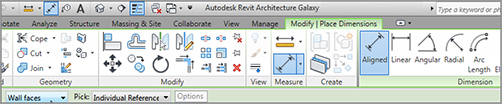
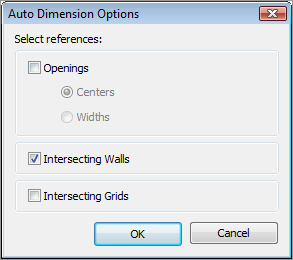
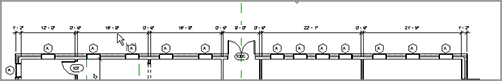
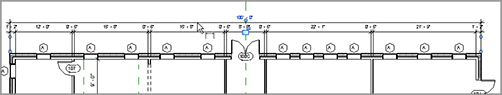
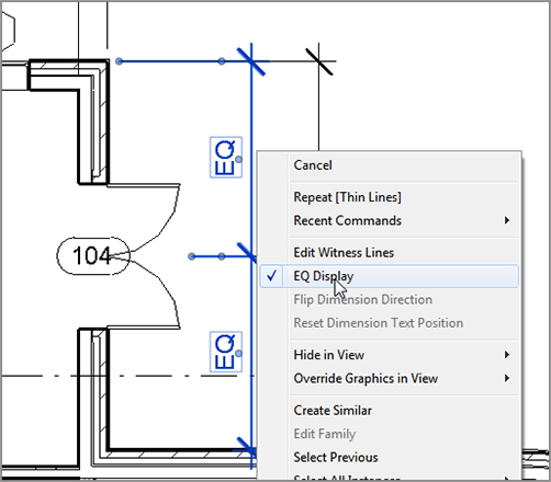
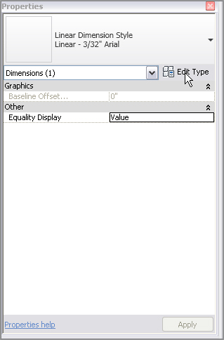
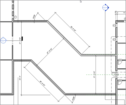
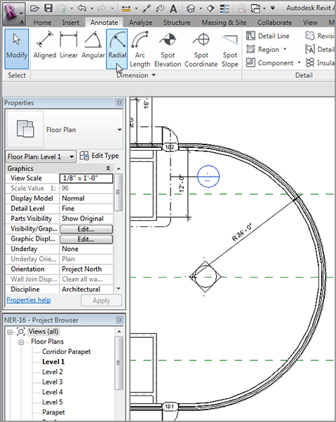
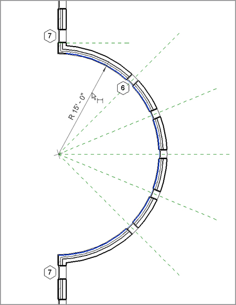
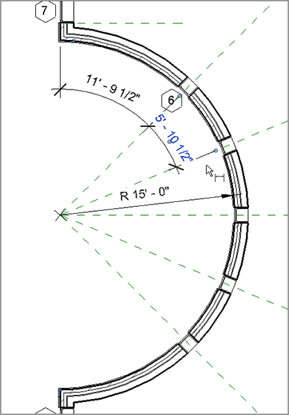
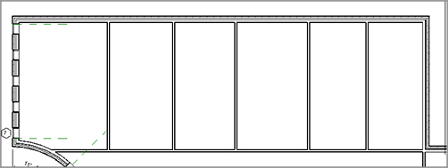
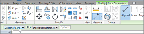
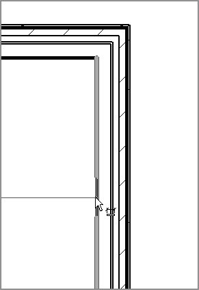
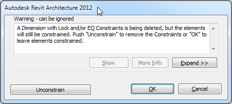
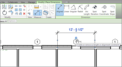
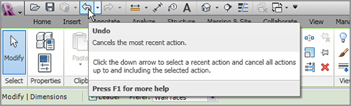
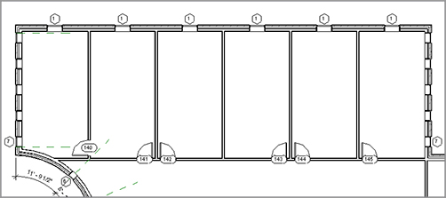
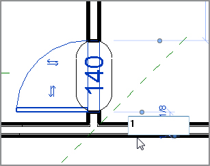
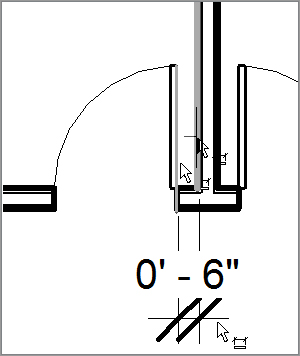
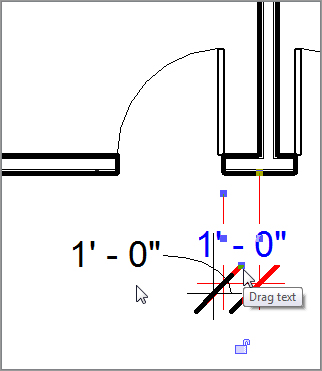
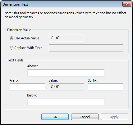
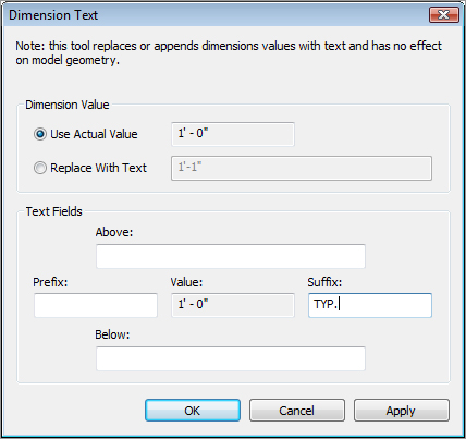
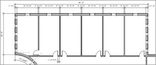
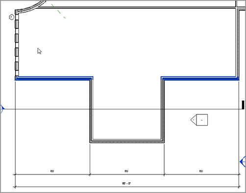
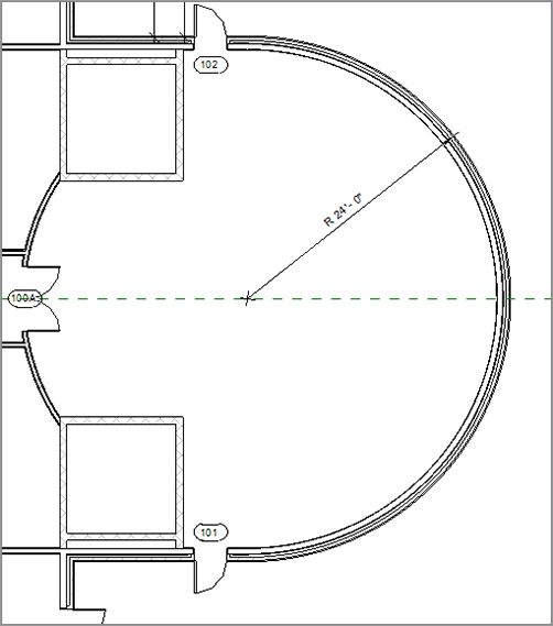
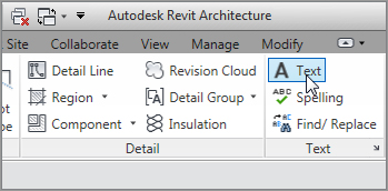
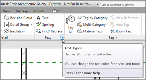
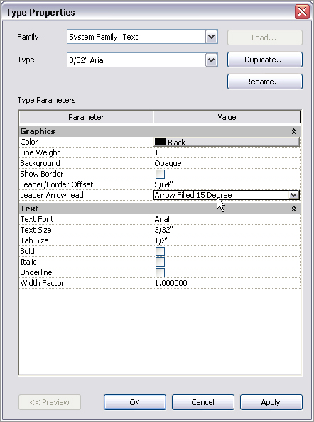
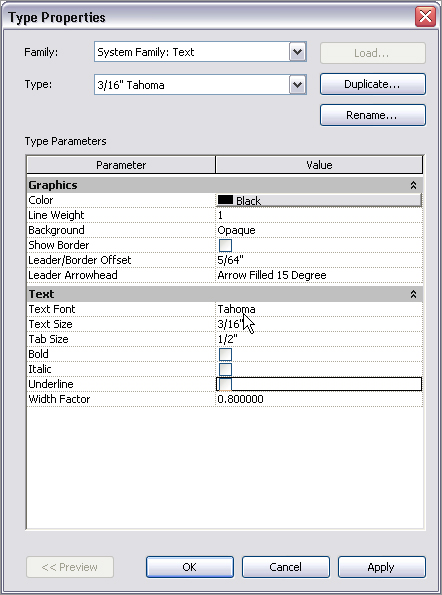
The focus of this chapter is to give you the ability to dimension and annotate a model. After the novelty of having a really cool model in 3D wears off, you need to buckle down and produce some bid documents. This is where Revit must prove its functionality. You should ask yourself, “Can Revit produce drawings consistent with what is acceptable to national standards, and more important, my company’s standards? And if so, how do I get to this point?” These are the questions that owners and managers will ask you. (If you are, in fact, an owner or a manager, I suppose you can ask yourself these questions.)


  • Dimensioning
  • Using dimensions as a layout tool
  • Placing text and annotations

Dimensioning


The answers to these questions begin right here with dimensioning and annotations. This is where you can start to make Revit your own. Also, when it comes to dimensioning, you will find in this chapter that dimensions take on an entirely new role in the design process.


I think you will like dimensioning in Revit. It is almost fun. Almost. Before you get started, let’s get one thing out of the way: you cannot alter a dimension to display an increment that is not true. Hooray! As you go through this chapter, you will quickly learn that when you place a dimension, it becomes not only an annotation but a layout tool as well.


The Dimension command has five separate types: Aligned, Linear, Angular, Radial, and Arc Length. Each has its importance in adding dimensions to a model, and each is covered separately in this section.


Let’s get started. To begin, open the file you have been following along with. If you did not complete Chapter 4, “Working with the Revit Tools,” go to the book’s website at www.sybex.com/go/revit2012ner. From there you can browse to Chapter 5 and find the file called NER-15.rvt.


Aligned Dimensions


The most popular of all the Revit Architecture dimensions is the Aligned dimension. This type of dimension will be used 75 percent of the time.


An Aligned dimension in Revit enables you to place a dimension along an object at any angle. The resulting dimension will align with the object being dimensioned. A Linear dimension, in contrast, will add a dimension only at 0, 90, 180, or 270 degrees, regardless of the item’s angle.


To add an Aligned dimension, perform these steps:


  1. 1. Go to the Level 1 floor plan.
  2. 2. Zoom in on the east wing of the building.
  3. 3. On the Annotate tab, click the Aligned button, as shown in Figure 5.1.
  4. 4. On the Options bar, you will see two drop-down menus with some choices, as shown in Figure 5.2. Make sure that you have Wall Faces selected.
  5. 5. The next menu lets you pick individual references or entire walls. Select Entire Walls from the menu.
    f0501.tif

    FIGURE 5.1 Starting the Dimension command from the Annotate tab

    f0502.tif

    FIGURE 5.2 The Options bar for the Dimension command. Notice the Options button.


  6. 6. On the far right of the Options bar is an Options button, which allows you to make further choices when selecting the entire wall. Click the Options button.
  7. 7. In the Auto Dimension Options dialog box, select Intersecting Walls. Do not select any other item (see Figure 5.3), and then click OK.
  8. 8. Zoom in on the north wall, as shown in Figure 5.4.
  9. 9. Pick (left-click) the north exterior wall. Notice that the dimensions are completely filled out.
    f0503.tif

    FIGURE 5.3 The Auto Dimension Options dialog box


  10. 10. Pick a point (to place the dimension) approximately 8´ (2400mm) above the north wall (see Figure 5.4).
    f0504.tif

    FIGURE 5.4 By choosing the Entire Walls option, you can add an entire string of dimensions in one click.


  11. 11. In true Revit form, you are still in the command unless you tell Revit you do not want to be. In this case, click the Options button on the Options bar (the same one you clicked before).
  12. 12. Deselect the Intersecting Walls option in the Auto Dimension Options dialog box and click OK.
  13. 13. Pick (left-click) the same wall. You now have a dimension traveling the entire length of the building.
  14. 14. Move your cursor above the first dimension string you added. Notice that the dimension will “click” when it gets directly above the first string.
  15. 15. When you see the dimension snap, pick that point (see Figure 5.5).

In many cases, you will need the ability to pick two points to create the dimension. What a world it would be if everything was as easy as the dimension string you just added. Unfortunately, it is not.

f0505.tif

FIGURE 5.5 Adding a major dimension by turning off the Intersecting Walls choice in the Auto Dimension Options dialog box


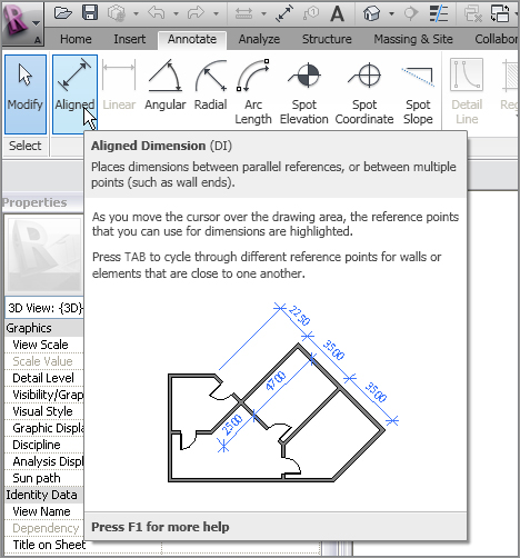
Creating Aligned Dimensions by Picking Points


Nine times out of 10, you will be picking two points to create the dimension. Usually in Revit this is quite simple—until you get into a situation where the walls are at an angle that is not 90 degrees. In a moment you will explore that issue, but for now, let’s add some straight dimensions:


  1. 1. Zoom in on the northeast portion of the east wing, as shown in Figure 5.6.
  2. 2. On the Annotate tab, click the Aligned button.
  3. 3. On the Options bar, choose Individual References from the Pick menu, as shown in Figure 5.6, and do the following:

    1. a. Pick the north wall marked 1 in Figure 5.6.
    2. b. Pick the horizontal wall that ties into the radial wall, illustrated as 2 in Figure 5.6.
    3. c. Place the dimension about 8´ (2400mm) to the right of the vertical wall, marked as 3 as shown in Figure 5.6.

  4. 4. With the Aligned Dimension command still running, pick the north wall again and do the following:

    1. a. Pick the outside face of the northern wall.
    2. b. Pick the centerline of the door, as shown in Figure 5.7, but do not press Esc or terminate the command.
    3. c. Pick the horizontal wall that ties into the radial wall, illustrated as 3 in Figure 5.7.
    4. d. Pick a point inside (to the left of) the first dimension illustrated as 4, as shown in Figure 5.7. This places the dimension string and finalizes the session.
    f0506.eps

    FIGURE 5.6 Placing the dimension by picking two objects


    You will now see that the actual dimension values are blue. Also, you will see a blue EQ icon with a dash through it (refer to Figure 5.7).


  5. 5. Click the blue EQ button, as shown in Figure 5.8. If the door was not exactly centered, this will force the door to move to an equal distance between the two walls.
  6. 6. Press Esc twice or click Modify.
f0507.eps

FIGURE 5.7 Adding a dimension string manually

f0508.eps

FIGURE 5.8 You can use the dimension string to move the door by clicking the EQ button.


Sometimes you may want to display the dimensions rather than the EQ that Revit shows as a default. To do so, follow along:


  1. 1. Select the dimension.
  2. 2. Right-click.
  3. 3. Choose EQ Display, as shown in Figure 5.9.

The dimensions will now show an increment.


Pretty cool. There is one last item involving Aligned dimensions that we should address: how do you dimension along an angle?

f0509.tif

FIGURE 5.9 Toggle off the EQ display.


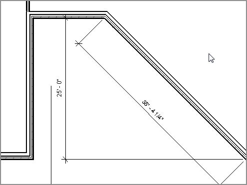
Dimensioning an Angle


No, not an angel, an angle. Adding this type of Aligned dimension is not the easiest thing to do in Revit. This is why we need to address the process as a separate item in this book. Here are the steps:


  1. 1. Zoom in on the corridor area (the link area between the east and west wings).
  2. 2. On the Annotate tab, click the Aligned button on the Dimension panel.
  3. 3. On the Options bar, be sure Pick is set to Individual References.
  4. 4. Zoom in close to the intersection of the two walls, shown in Figure 5.10.
  5. 5. Hover your pointer over the core intersection, as shown in Figure 5.10.
  6. 6. Tap the Tab key until you see the square grip appear.
  7. 7. When the square grip appears, pick it (left-click), as shown in Figure 5.10.
    f0510.eps

    FIGURE 5.10 Press the Tab key to select the point shown.


  8. 8. Move to the other intersection of the angled wall.
  9. 9. Hover your cursor over this core intersection, as shown in Figure 5.11.
  10. 10. Tap the Tab key until you see the same square grip.
  11. 11. Pick the square grip.
  12. 12. Now the dimension is following your pointer. Pick a third point about 8´ (2438mm) away from the angled wall, as shown in Figure 5.11.
  13. 13. On the left end of the Ribbon, select the Modify button. This ends the command.

Unfortunately, you had to dimension to the core of the wall. This is the last place you would ever need to take a dimension from. At this point, the dimension needs to be “stretched” to the outside, finished face of the brick, as you’ll see next.


Editing the Witness Line


Every dimension in Revit Architecture has its own grip points when selected. This is similar to most CAD applications. Two of these grips control the witness line. The witness line is the line “attached” to the item being dimensioned. Because you had to take this dimension from the core of the wall, the witness lines need to be dragged to the outside face of the brick:


  1. 1. Select the angled dimension. Notice the blue grips appear.
  2. 2. On the left side of the dimension, pick and hold the grip in the middle of the dimension line, as shown in Figure 5.12.
  3. 3. Drag the blue grip to the outside face of the brick. You will know you are in the right spot because you will see a small dot appear, as shown in the magnified segment of Figure 5.12.
  4. 4. Repeat the procedure for the other side.

Trust me—this is worth practicing now, before you get into a live situation. If you have already run into this situation, you know exactly what I mean.


You need to look at one more procedure for tweaking an Aligned dimension: overriding a dimension’s precision.

f0511.eps

FIGURE 5.11 Picking the second point along the wall and placing the dimension

f0512.eps

FIGURE 5.12 Dragging the witness line’s grip


Overriding the Precision


When you dimension a wall at an angle such as this, the dimension usually comes out at an uneven increment. In most cases, you do not want to override every dimension’s precision just for this one, lone dimension to read properly. In this situation, you want to turn to the dimension’s Type Properties:


  1. 1. Select the angled dimension.
  2. 2. In the Properties dialog, click the Edit Type button, as shown in Figure 5.13.
  3. 3. Click the Duplicate button, as shown in Figure 5.14.
  4. 4. In the Name dialog box that opens, name the new dimension style Linear – 3/32˝ Arial – 1/4˝ precision. For the metric users, it is Linear – 2mm Arial 10mm precision. Click OK.
    f0513.tif

    FIGURE 5.13 Clicking the Edit Type button to begin creating a new dimension style


  5. 5. Scroll down to the Text category. There, near the bottom, you will see a row for Units Format. Next to the Units Format row is a button that displays a sample increment. Click it (see Figure 5.14).
  6. 6. In the Format dialog box, deselect the Use Project Settings option.
    f0514.eps

    FIGURE 5.14 Select the button in the Text category to access the dimension’s precision.


  7. 7. Choose To The Nearest 1/4˝ (To The Nearest 10) from the Rounding drop-down menu (see Figure 5.15).
    f0515.tif

    FIGURE 5.15 Changing the dimension’s precision. Notice some of the other available choices.


  8. 8. Click OK twice.
  9. 9. Notice that the dimension is now rounded to the nearest 1/4˝ (10mm). In this case, it is rounded to a whole number.

Although Aligned dimensions will bear the brunt of your dimensioning, there are still plenty of other dimension types waiting for you to use.


Linear Dimensions


Linear dimensions are used less frequently than most of the other dimensions. Unlike in AutoCAD, in which Linear dimensions are the go-to dimension, they are put on the bench for most of the game in Revit. The best use for a Linear dimension is when you want to put a straight dimension across nonlinear (angled) geometry, as follows:


  1. 1. Zoom back in on the corridor area.
  2. 2. On the Annotate tab, select the Linear Dimension button. Notice that you cannot select the entire wall. That option has been taken away. Instead, Revit requires you to pick a point.
  3. 3. Move your cursor over the inside corner, at the bottom intersection of the corridor. Make sure you are exactly over the exterior intersection of the brick. You will know you are there by the blue dot that shows up, as shown in Figure 5.16.
    f0516.eps

    FIGURE 5.16 Selecting the finished exterior corner of the brick. You will see a small blue dot appear, indicating you can pick the start of the dimension.


  4. 4. When you see the dot, pick the corner.
  5. 5. Pick the same spot on the other end of the wall, as shown in Figure 5.17. When you pick the second corner, the dimension will follow your cursor in a straight direction.
  6. 6. Move your cursor to the left approximately 8´ (2400mm) past the first point that you picked, and pick the third point to place the dimension (see Figure 5.17).
  7. 7. Press Esc. See Figure 5.18 for the completed dimension.
f0517.eps

FIGURE 5.17 When you add a Linear dimension to an angled wall, you will get a straight dimension.

f0518.tif

FIGURE 5.18 Changing the dimension to reflect the new rounded dimension


Aligned and Linear dimensions are the two dimension styles that pertain to straight dimensioning. The next three dimension procedures add dimensions to angled and radial geometry.


Angular Dimensions


Angular dimensioning comes close to needing no introduction at all. But I will introduce it anyway. Angular dimensions are used to calculate and record the angle between two items. These two items are usually walls. Of course, you will add an Angular dimension to your lovely corridor walls:


  1. 1. Zoom back in on the corridor if you are not there already.
  2. 2. On the Annotate tab, select the Angular Dimension button, as shown in Figure 5.19.
  3. 3. For the first wall, pick the finished, inside face of the upper-left corridor wall, which is marked 1 in Figure 5.19.
  4. 4. Pick the finished, inside face of the angled corridor wall, which is marked 2 in Figure 5.19.
  5. 5. Move your cursor to the left about 8´ (2400mm), and place the dimension that is marked 3 in Figure 5.19.
  6. 6. Press Esc.
  7. 7. Repeat the steps for the bottom of the corridor.
  8. 8. Add the rest of the dimensions, as shown in Figure 5.20. This completes the dimensioning of the corridor area.
f0519.eps

FIGURE 5.19 Placing an Angular dimension means picking two walls and then a point to place the dimension.

f0520.tif

FIGURE 5.20 Finish placing the corridor dimensions.


If you would like to place the dimensions in different locations, feel free to do so.


The next set of dimensions pertains to radial geometry. You can finally get out of this corridor!


Radial Dimensions


Radial dimensions are used to, well, measure the radius of an item. You are lucky that Revit knows that you are adding a Radial dimension to a building component. This means that the many different choices provided by a CAD application are taken away, leaving just the basics.


The following procedure will lead you through adding a Radial dimension:


  1. 1. Zoom in on the east radial entry in the east wing.
  2. 2. On the Annotate tab, select the Radial Dimension button.
  3. 3. Pick the outside face of the radial wall, as shown in Figure 5.21.
  4. 4. Place the Radial dimension somewhere that makes sense. If your model looks like Figure 5.21, you may proceed. If it does not, go back and try it again.
    f0521.tif

    FIGURE 5.21 Adding a Radial dimension is about as straightforward as it gets.


  5. 5. Pan all the way to the west radial end of the west wing, as shown in Figure 5.22.
  6. 6. On the Annotate tab, select the Radial Dimension button.
  7. 7. Dimension to the finished outside face of the brick, and place your dimension in a location similar to that shown in Figure 5.22.
f0522.tif

FIGURE 5.22 Adding the second Radial dimension


If you are careful in how you add a Radial dimension, you will find this process quite simple. The next type of dimension, however, can be a little tricky.


Arc Length Dimensions


Measuring the length of an arc is a handy capability that was added back in the 2009 release. I have found the Arc Length dimension extremely useful in locating items such as windows along an arc. That is, in fact, what you need to do in the west wing of the building.


The following procedure will lead you through adding an Arc Length dimension:


  1. 1. Zoom in on the west radial entry of the west wing, as shown in Figure 5.23.
  2. 2. On the Annotate tab, select the Arc Length button, as shown at the top left of Figure 5.23.
  3. 3. Pick the finish face exterior face of the brick on the radial wall.
  4. 4. Pick the centerline of the uppermost window in the radial wall. The NO symbol will not change, but you will be able to pick the window centerline.
  5. 5. Pick a point along the exterior face of brick that runs along the vertical intersecting wall, illustrated as 3 in Figure 5.23.
  6. 6. Pick a point in which to place the dimension 4.
f0523.eps

FIGURE 5.23 Placing an Arc Length dimension involves four separate picks.


Let’s try it again. This time the dimension will be taken from the first window (the one you just dimensioned) to the second window. The process will be exactly the same:


  1. 1. On the Annotate tab, select the Arc Length button if you are not still in the command.
  2. 2. Pick the exterior face of brick along the radial wall.
  3. 3. Pick the first window’s centerline again.
  4. 4. Pick the second window’s centerline.
  5. 5. Pick a point to place the dimension (see Figure 5.24).

Now that you have experience adding dimensions to record placement of items, it is time to see how you can physically use dimensions as a layout tool.

f0524.tif

FIGURE 5.24 Adding a second Arc Length dimension


Using Dimensions as a Layout Tool


When it comes to dimensions, using them as a layout tool is my favorite topic. “Okay, fine,” you may say. “I can do that in CAD.” Well, not quite. You see, in Revit you cannot alter a dimension to reflect an increment that is not accurate. You can, however, select the item you are dimensioning, and then type a new number in the dimension. At that point, the item you are dimensioning will move. The result is an accurate dimension.


The first task you need to explore is how to equally constrain a string of dimensions. You were exposed to this task earlier in the chapter, but now, let’s really dig in and gain some tangible experience using this tool.


For this procedure, you will add some more walls to the west wing, and then constrain them by using the EQ dimension function:


  1. 1. In the Project Browser, go the Level 1 floor plan (not a ceiling plan!).
  2. 2. Zoom in to the west wing of the building.
  3. 3. Draw two interior-partition (2 hr) corridor walls, as shown in Figure 5.25.
    f0525.eps

    FIGURE 5.25 Adding two corridor walls


  4. 4. Draw five walls, as shown in Figure 5.26. They do not have to be an equal distance from one another.
    f0526.tif

    FIGURE 5.26 Place these walls as quickly as possible, and don’t worry about their spacing.


  5. 5. On the Annotate tab, click the Aligned Dimension button.
  6. 6. Also on the Options bar, be sure the justification is set to Center Of Core (see Figure 5.27).
    f0527.tif

    FIGURE 5.27 Changing the options for the dimension


  7. 7. Zoom in on the left exterior wall, as shown in Figure 5.28.
  8. 8. Hover your pointer over the wall. Do you notice that Revit is trying to locate the center of the wall? In this instance, you do not want this (even though you just told Revit to do that).
  9. 9. You want Revit to start this dimension string by using the interior face of the finished wall. To do this, hover your pointer over the inside face of the wall, as shown in Figure 5.28.
  10. 10. When your cursor is over the inside face of the wall, tap the Tab key on your keyboard until Revit highlights the inside face of the wall.
  11. 11. Pick the inside face of the wall.
    f0528.eps

    FIGURE 5.28 Press the Tab key to filter to the desired reference of the wall.


  12. 12. Move your cursor to the right until you pass over the first interior wall. Notice that the core centerline of the interior is highlighted. When you see this, pick the wall, as shown in Figure 5.29.
  13. 13. After you pick the first interior partition, move to the right and pick the center of the next wall.
  14. 14. Repeat the procedure until you get to the last wall (see Figure 5.29).
f0529.eps

FIGURE 5.29 Adding a string of dimensions to the interior walls


When you get to the exterior wall to the right, you will encounter the same issue. You want this string of dimensions to go to the inside face, not the core of the exterior wall:


  1. 1. Hover your cursor over the inside face of the wall and tap the Tab key on your keyboard until the inside face of the wall becomes highlighted, as shown in Figure 5.30.
  2. 2. When you locate the inside face, pick it.
  3. 3. Move your cursor up the view. Notice that the entire dimension string is following.
  4. 4. Placing a dimension in Revit is a little awkward, but you will get the hang of it. You need to pick a point away from the last dimension in the string, as shown in Figure 5.31, almost as if you are trying to pick another item that is not there. When you do this, the dimension will be in place.
f0530.tif

FIGURE 5.30 Press Tab to locate the inside face of the wall.

f0531.eps

FIGURE 5.31 Picking a point away from the last dimension to place the string


Now that the dimension string is in place, it is time to move these walls to be equal distances apart from one another. Notice that, after you placed the dimension string, the familiar blue icons appeared. You can use them as follows:


  1. 1. Find the EQ icon in the middle of the dimension string and pick it. The slash through it is now gone, and the walls have moved, as shown in Figure 5.32.
  2. 2. Press Esc twice to release the selection and exit the Aligned Dimension command.
f0532.eps

FIGURE 5.32 Before and after the EQ icon is selected


Because these walls are not constrained to always be equal, if one exterior wall is moved, these five interior partitions will always maintain an equal relationship to one another—that is, as long as this dimension string is still associated with the walls.


In Revit Architecture, you can choose to keep the walls constrained or to use the dimension only as a tool to move the walls around.


Constraining the Model


Choices you make early in the design process, such as constraining a model, can either greatly benefit or greatly undermine the project’s flow. As you gain more experience using Revit Architecture, you will start hearing the term overconstrained. This is a term for a model that has been constrained in so many places that any movement of the model forces multiple warnings and, in many cases, errors that cannot be ignored.


Given that, how you choose to constrain your model is up to you. You will learn how to constrain (and of course unconstrain) your model in this section, but deciding when and where to constrain your model will vary from project to project.


Unconstraining the Walls


The string of equal dimensions you now have in place has created a constraint with these walls. To unconstrain them, follow along:


  1. 1. Select the dimension string.
  2. 2. Press the Delete key on your keyboard.
  3. 3. Revit gives you a warning, as shown in Figure 5.33. You must then choose whether to unconstrain the elements.
    f0533.tif

    FIGURE 5.33 A Revit warning pertaining to the constraint of the walls


    If you click the Unconstrain button, the EQ dimension will disappear as well as any constraint on the walls. If you move the exterior wall, the newly spaced walls will not reposition themselves.


  4. 4. Click OK. You will learn how to unconstrain these walls via a different method.
  5. 5. Select one of the interior walls that were part of the EQ dimension string.
  6. 6. You will now see the EQ icon buried in the middle wall. Click this icon, and it will release the constraint set for the walls (see Figure 5.34). You are now free to move around the building. (Note that the EQ icon may be hiding behind a wall in the middle of the array. Zooming in will make the icon larger and easier to pick.)
f0534.eps

FIGURE 5.34 Unconstraining the walls


Now that you have experience with dimension equality constraints, it is time to learn about a different type of constraint that involves locking items together at a distance.


Locking a Dimension


At times you may want to always hold a dimension, no matter what else is going on around it. You can do this by physically adding a dimension to an item and then locking that dimension in place. For example, if you want to lock the middle space to a specific dimension, you simply add a dimension and lock it down. Sound easy? It is!


  1. 1. On the Annotate tab, click the Aligned Dimension button.
  2. 2. On the Options bar, change the alignment to Wall Faces.
  3. 3. Pick the inside faces of the two middle partitions, as shown in the upper-left corner of Figure 5.35.
    f0535.tif

    FIGURE 5.35 You can add a dimension and lock the distance between two items.


  4. 4. After you place the dimension, a blue padlock icon will appear. When it does, pick it. It should then change to an unlocked padlock icon. When you see this, press Esc twice or click Modify to terminate the command.
  5. 5. Select the left wall that has been dimensioned.
  6. 6. Move the wall to the right 2´–0˝ (600mm). Notice that the right wall moves as well. Note that if you get a “constraints are not satisfied” message, you need to go back and “un-EQ” the five walls.
  7. 7. Click the Undo button, as shown in Figure 5.36.
    f0536.tif

    FIGURE 5.36 Click the Undo button.


  8. 8. Delete the dimension.
  9. 9. When you get the warning, click the Unconstrain button.
  10. 10. Save the model.
  11. 11. Add doors and windows to the plan, as shown in Figure 5.37. They can be any type of door or window you choose—just try to keep them similar to the ones in Figure 5.37. Also, placement does not matter. You will adjust this in the next procedure.
f0537.tif

FIGURE 5.37 Adding doors and windows to the floor plan


In the next section, you will start using dimensions as a tool to physically move elements around. Although this one might seem like an exercise in futility, the practice is quite relevant to what you will encounter in future projects.


Using Dimensions to Move Objects


As I have mentioned before, you cannot type over a dimension and cause the value in that dimension to be inaccurate. Revit does provide tools to get around this. When you add a dimension and select the object being dimensioned, your dimension will turn blue. This is a temporary dimension, which can be edited. Consequently, the object being dimensioned will move.


The objective of this procedure is to select an item and modify the temporary dimension, in effect moving the object:


  1. 1. Zoom in on the left side of the west wing, as shown in Figure 5.38.
  2. 2. Select the door, as shown in Figure 5.38. Notice that there is a blue dimension on both sides of the door. These are temporary dimensions.
  3. 3. Pick the blue text in the lower temporary dimension, as shown in Figure 5.38. (The text might be obscured by the wall, but if you hover over it, it will activate and then you can select it.)
    f0538.tif

    FIGURE 5.38 When you type a different value, the temporary dimension will move the object.


  4. 4. Type 1. (300mm). For imperial users, this is the equivalent of 1´–0˝. The door moves.
  5. 5. Press the Esc key to release the door.

This procedure used a temporary dimension that appeared when you selected the item. After you edited the dimension, it went away. In the next procedure, you will add a permanent dimension and do the same thing:


  1. 1. On the Annotate tab, select the Aligned Dimension button.
  2. 2. Place a dimension between the door and the wall, as shown in Figure 5.39.
    f0539.tif

    FIGURE 5.39 Placing a dimension (note that the door tags have been removed for clarity)


  3. 3. Press the Esc key twice.
  4. 4. Select the door shown in Figure 5.40. Notice that the dimension turns small and blue. It is now ready to be modified.
    f0540.eps

    FIGURE 5.40 Making adjustments with the actual dimension


  5. 5. When you see the dimension turn blue, select the text and type 1 (1´–0˝) (300mm). The door adjusts to the 1´–0˝ (300mm) increment.
  6. 6. Press the Esc key or click anywhere in open space to clear the selection.
  7. 7. Select the dimension.
  8. 8. Notice that there is a blue grip just underneath the text. Pick the grip and move the text out from between the extension lines, as shown in Figure 5.41. Notice that Revit will place a leader (an arrow line extending from the model to your text) in the text.

The process of using dimensions to move objects takes some getting used to. The next procedure delves into making further modifications to dimensions, and provides a nice fail-safe procedure embedded within the dimension properties.

f0541.tif

FIGURE 5.41 By grip-editing the text, you can slide it to a cleaner location. Revit automatically places a leader for the text to the dimension line.


Using Dimension Text Overrides


Although I just told you that you can’t override a dimension, the following steps get around that problem. In many cases, you may want text or, more commonly, a prefix or a suffix within a dimension. You can do all three in Revit Architecture:


  1. 1. Select the 1´–0˝ (300mm) dimension.
  2. 2. Notice that the text turns blue. As you know, blue means that this item is editable in Revit. Pick the text. You should see a dialog box like the one in Figure 5.42.
  3. 3. Under Dimension Value, click Replace With Text.
    f0542.tif

    FIGURE 5.42 The Dimension Text dialog box


  4. 4. Type 1´–1˝ (325mm) and press Enter.
  5. 5. You will get an Invalid Dimension Value message, as shown in Figure 5.43. Revit will not allow you to do such a foolish thing. Click Close.
    f0543.eps

    FIGURE 5.43 Any numeric value will trigger a warning in Revit. You simply cannot type a value over a dimension.


  6. 6. In the Dimension Text dialog box, click Use Actual Value.
  7. 7. Under Suffix, type TYP., as shown in Figure 5.44.
  8. 8. Click OK.
f0544.tif

FIGURE 5.44 Under Dimension Value, choose Use Actual Value, and type TYP. as the suffix.


As a closing practice for dimensioning, move the rest of the doors along this wall to a 1´–0˝ (300mm) increment from the finished, inside face of the wall to the door opening. Also, dimension the floor plan as shown in Figure 5.45 and Figure 5.46.

f0545.tif

FIGURE 5.45 The dimensional layout for the north part of the west wing

f0546.tif

FIGURE 5.46 The dimensional layout for the south part of the west wing


Placing Text and Annotations


Text in Revit Architecture is going to be a love/hate relationship for every Revit user. You will love text because it will automatically scale with the view’s scale. You will hate it because the text editor is something of a throwback from an earlier CAD application. Either way, the procedure for adding text does not change with your feelings toward it.


To begin, open the file you have been following along with. If you did not complete Chapter 4, go to the book’s web page at www.sybex.com/go/revit2012ner. From there you can browse to Chapter 5 and find the file called NER-16.rvt.
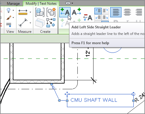

The objective of this procedure is to simply add text to the model, format it, and then add and format a leader:


  1. 1. In the Project Browser, go to the Level 1 floor plan.
  2. 2. Zoom in on the east wing’s radial entry area, where the elevator shafts are, as shown in Figure 5.47.
    f0547.tif

    FIGURE 5.47 The radial entry


  3. 3. On the Text panel of the Annotate tab, click the Text button, as shown in Figure 5.48.
    f0548.tif

    FIGURE 5.48 Click the Text button on the Text panel of the Annotate tab.


  4. 4. In the Type Selector, select Text : 3/32˝ Arial.
  5. 5. On the Format panel, you have choices for a leader. For this example, select the No Leader button. It is the button with the A on it, as shown in Figure 5.49.
  6. 6. To place the text, you can pick a point or drag a window. Left-click at the point labeled 1 in Figure 5.49. Keep the button down.
  7. 7. Drag the cursor to the point labeled 2 in Figure 5.49 and let the button up.
    f0549.eps

    FIGURE 5.49 Placing text


  8. 8. Type CMU SHAFT WALL.
  9. 9. Click a point in the view outside the text box. You now have a note in the model. The text wraps to fit the size of the window you dragged.
  10. 10. Press the Esc key twice or click Modify.
  11. 11. Select the text.
  12. 12. On the Format panel, review the choices you have to add a leader to the text.
  13. 13. Click the Add Left Side Straight Leader button, as shown in Figure 5.50. This option adds a leader to the left end of the text.
  14. 14. By clicking the grips and moving the text around, configure the text and the leader to resemble Figure 5.50.
f0550.tif

FIGURE 5.50 Adding and stretching a leader


Adding Leader Text


You can add text to a model by placing a leader first and then adding the text within the same command. Although in Revit you can add leaders to all text, you can choose to add text to a model with or without a leader.


The objective of the following steps is to place text with a leader:


  1. 1. On the Text panel of the Annotate tab, select the Text button.
  2. 2. On the Format panel, click the Two Segments button, as shown in Figure 5.51.
  3. 3. Pick a point near the radial wall, shown as 1 in Figure 5.51.
  4. 4. Pick a second point similar to 2, shown in Figure 5.51.
  5. 5. Pick a third point just to the right of the second point.
  6. 6. Type FULL HEIGHT RADIAL WALL.
  7. 7. Click an area outside the text.

Now that you can add text to a model, it is time to investigate how to modify the text after you add it. You can start with that arrowhead on the end of the leader.

f0551.eps

FIGURE 5.51 Adding a piece of leader text


Changing the Leader Type


It almost seems as though Revit uses the ugliest leader as a default, forcing you to change it immediately. The large arrowhead you saw in the previous figure is not the only arrowhead Revit provides—had that been the case, Revit may have never have even gotten off the ground!


To change the arrowhead that Revit uses with a text item, follow this procedure:


  1. 1. On the Text panel of the Annotate tab, you will see a small arrow pointing down and to the right, as shown in Figure 5.52. Click it.
    f0552.tif

    FIGURE 5.52 Accessing the text properties


  2. 2. Change the Leader Arrowhead parameter to Arrow Filled 15 Degree, as shown in Figure 5.53.
    f0553.tif

    FIGURE 5.53 Changing that ugly arrow


  3. 3. Click OK. You have changed a Type parameter.

Now that’s a handsome-looking arrowhead. The next item to address is how to modify the placement of text after you add it to the model.


Modifying the Text Placement


With any text item in Revit, you can select the text in your model, and you will see grips for adjusting text: two grips on the text box, two on the leader, and a rotate icon.


Your next objective is to modify the text placement and to make the necessary adjustments:


  1. 1. Select the text you just added to the model.
  2. 2. Pick the right blue grip.
  3. 3. Stretch the text window to the left until it forces the text to wrap, as shown in Figure 5.54.
f0554.tif

FIGURE 5.54 Wrapping the text by using the right grip


Observe the rotate icon. You don’t need to rotate the text here, but notice that it is there, for future reference.


Modifying the placement of text is a straightforward process. Changing the actual font and size of the text in a model is another story, and involves further investigation.


Changing Text Properties


Of course, you can change the font for text. You can also change the height and the width. Keep in mind, however, that the text height you specify is the actual text height you want to see on the sheet. You no longer have to multiply the desired text height to a line type scale. Revit understands that text is scaled based on the view’s scale.


To modify the text appearance, run through the following procedure:


  1. 1. Pick the Text Types arrow in the corner of the Text panel, as you did when you changed the leader type.
  2. 2. Click the Duplicate button.
  3. 3. Call the new text 3/16˝ Tahoma (3.5mm Tahoma).
  4. 4. Click OK.
  5. 5. Change the Text Font setting to Tahoma.
  6. 6. Change the Text Size setting to 3/16˝ (3.5mm), as shown in Figure 5.55.
    f0555.tif

    FIGURE 5.55 Changing the text values in the Type Properties dialog box


  7. 7. Change the Width Factor setting to 0.8.
  8. 8. Click OK twice.

You have now successfully created a text style. Of course, this large, nonuniform text is not proper in this context. You can use that new type easily:


  1. 1. Start the Text command.
  2. 2. In the Type Selector, verify that your new text is in the list.

Are You Experienced?


Now you can…


  • add a multitude of different types of dimensions to your model by simply altering the options associated with the Dimension command
  • equally constrain items in a model by adding a string of dimensions and clicking the EQ button
  • use your dimensions as a layout tool, keeping the items constrained even after the dimension is deleted
  • add text to a model by starting either with a leader or just a paragraph of text
  • change the text type and arrowhead type for leader text

Aug 3, 2021 | Posted by in Building and Construction | Comments Off on 5: Dimensioning and Annotating
Premium Wordpress Themes by UFO Themes