Roofs come in all shapes and sizes. Given the nature of roofs, there is a lot to think about when you place a roof onto your building. If it is a flat roof, pitch is definitely a consideration. Drainage to roof drains or scuppers is another consideration as well. But how about pitched roofs? Now we are in an entirely new realm of options, pitches, slopes, and everything else you can throw at a roof design. Also, there are always dormers that no pitched roof can live without! Do the dormers align with the eaves, or are they set back from the building?
This book can’t address every situation you will encounter with a roof system, but it will expose you to the tools needed to tackle these situations yourself. The techniques you will employ in this chapter start with the concept of adding a roof to the model by using the actual floor-plan footprint. As with floors, you will also build the roof’s composition for use in schedules, quantities, and material takeoffs.
The command you’ll probably use most often when working with roofs is the one to place a roof by footprint. Essentially, you will create a roof by using the outline of the building in plan view. There are three roof types you can place by using a footprint:
A flat roof. (Okay, no roof is actually flat, but you get the point.)
A gable roof, which has two sides that are sloped and its ends left open.
A hip roof, which has all sides sloped.
You have only these options while placing a roof by footprint because you are looking at the roof in the plan, which limits your ability to place a roof with nonuniform geometry. Later in the book, you will explore doing just that, but for now let’s start with placing a flat roof by using the footprint of the east wing.
Flat Roofs by Footprint
To begin, open the file you have been following along with. If you did not complete Chapter 6, “Floors,” go to the book’s web page at www.sybex.com/go/revit2012ner. From there you can browse to Chapter 7 and find the file called NER-18.rvt.
The objective of this procedure is to create a flat roof by outlining the building’s geometry in the plan:
1. In the Project Browser, double-click the Roof view in the Floor Plans section (be careful not to click Roof in the Ceiling plans).
2. Zoom in to the east wing.
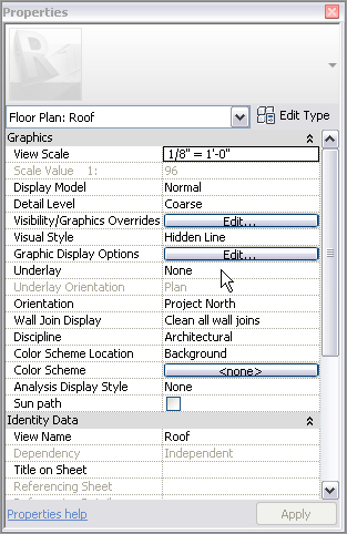
3. In the view Properties, find the Underlay row and select None from the menu, as shown in Figure 7.1.
4. Click the Apply button.
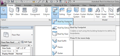
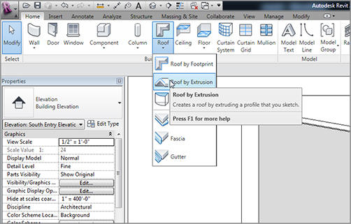
5. On the Home tab, click Roof Roof By Footprint, as shown in Figure 7.2.
FIGURE 7.2 Clicking Roof By Footprint on the Home tab of the Design bar
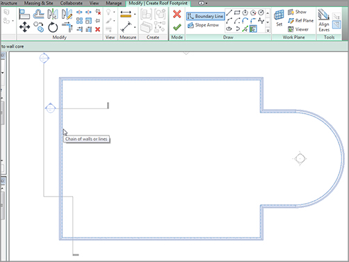
6. On the Modify | Create Roof Footprint tab, be sure the Pick Walls button on the Draw panel is selected, as shown at the right of Figure 7.3.
7. On the Options bar, deselect Defines Slope.
8. In the Options bar, make sure the overhang is set to 0´ 0˝(0).
9. Deselect Extend Into Wall Core (if it is selected).
10. Hover your pointer over the leftmost vertical wall. Notice that it becomes highlighted. When you see the wall highlight, press the Tab key on your keyboard. Notice that all the perimeter walls highlight. When they do, pick (left-click) anywhere along the wall. This places a magenta sketch line at the perimeter of the building (see Figure 7.3).
FIGURE 7.3 Adding a sketch line to the perimeter of the building by picking walls
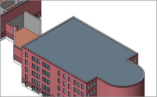
11. On the Modify | Create Roof Footprint tab, click Finish Edit Mode.
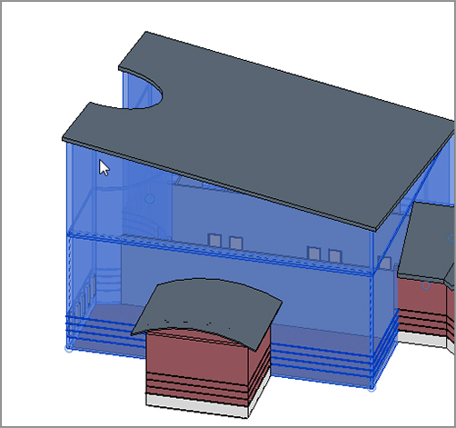
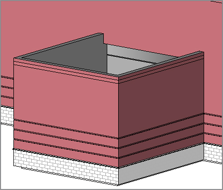
13. If you have the elevator shaft masonry walls sticking out of your roof, select all of them, and in the Properties dialog box, change the top constraint to Up To Level: Roof.
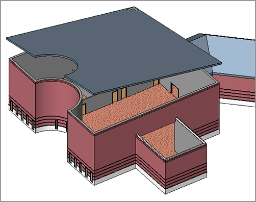
FIGURE 7.4 The roof has been added. You still have a lot of work to do, though.
With the roof added, step 1 is out of the way. Now we need to create a roof system. You will do this the same way you created your floor system in Chapter 6.
Creating a Flat Roof System
Although you can use this system for a pitched roof, the steps for a flat roof system differ slightly. In Revit Architecture, there are two ways to look at a roofing system. One way is to create it by using all of the typical roof materials and a large space for the structural framing. In this book, I do not recommend that approach. Creating a roof by using only the roofing components is necessary, but adding the structure will lead to conflicts when the actual structural model is linked with the architectural model. Also, it is hard for the architect to guess what the depth of the structural framing will be. In Revit, you want each component to be as literal and as true to the model as possible. The second way to look at a roofing system, as you are about to explore, is to build the roof in a literal sense—that is, to create the roof as it would sit on the structural framing by others.
The objective of this procedure is to create a roof system by adding layers of materials:
1. Select the roof. (If you are having trouble selecting the roof, remember the Filter tool.)
2. In the Properties dialog box, click Edit Type.
3. Click Duplicate.
4. Call the new roof system 4˝ Insulated Concrete Roof (100mm Insulated Concrete Roof).
5. Click OK.
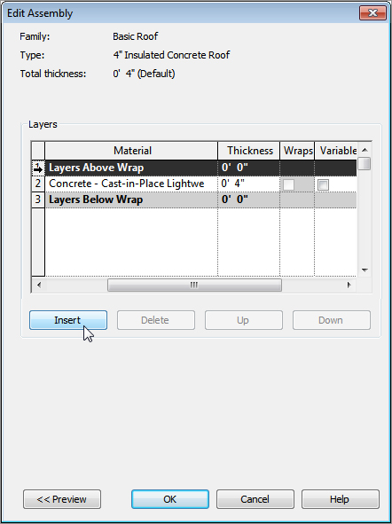
6. Click the Edit button in the Structure row.
7. Change the material of Structure 1 to Concrete – Cast-in-Place Lightweight Concrete. (You do this by clicking in the cell and then clicking the […] button. You can then select the material from the menu.) After the material is selected, click OK.
8. Change the structure Thickness to 4˝ (100mm), as shown in Figure 7.5.
9. Insert a new layer above the core boundary. (You do this by clicking the number on the left side of the Layers Above Wrap row, and clicking the Insert button below the Layers section, as shown in Figure 7.5.)
FIGURE 7.5 Changing the material and adding a layer
10. Change the function of the new layer to Thermal/Air Layer [3].
11. Click in the Material cell.
12. Click the […] button to open the Materials dialog box.
13. Select Insulation / Thermal Barriers – Rigid Insulation for the material.
14. Click OK.
15. Change Thickness to 4˝ (100mm).
16. Click the Variable button. When you modify the roof, this insulation layer will warp, enabling you to specify roof drain locations.
17. Insert a new layer above Insulation.
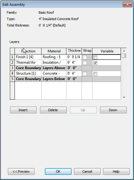
18. Give it a Function of Finish 1 [4].
19. Select Roofing – EPDM Membrane.
20. Click OK.
21. Change Thickness to 1/4˝ (6mm), as shown in Figure 7.6.
24. Press Esc or click in open space to clear the roof selection.
Phew! That was a long procedure. It was worth it, though. You will be using this process a lot in Revit Architecture.
For the next procedure, you will add some roof drain locations and then taper the insulation to drain to those locations.
Tapering a Flat Roof and Adding Drains
If you went through the floor procedure in Chapter 6, you will see that the process for tapering a roof is similar to pitching a floor. You may have also noticed that creating a roof system is identical to creating a floor system.
To taper the roof insulation, you must first divide the roof into peaks and valleys, and then specify the drain locations based on the centering of these locations:
1. In the Project Browser, make sure you are in the Roof floor plan.
2. Select the roof. (You may have to use the Filter tool here.)
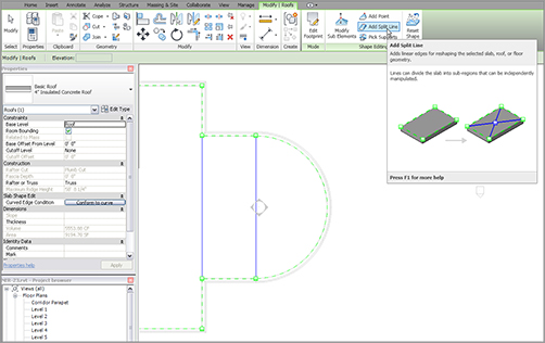
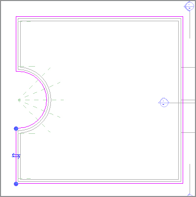
3. With the roof selected, select the Create Split Lines button shown in Figure 7.7.
4. Draw a line from the points shown in Figure 7.7.
FIGURE 7.7 Start splitting the radial portion of the roof.
5. Press Esc.
6. Select the roof.
7. Click the Add Point button, as shown in Figure 7.8.
8. Add two points at the midpoints marked as 1 and 2 in Figure 7.8.
FIGURE 7.8 Click the Add Point button and add the two points.
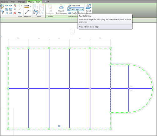
9. Click the Add Split Line button and draw a ridge across the entire length of the building, from point 1 to point 2, as shown in Figure 7.9.
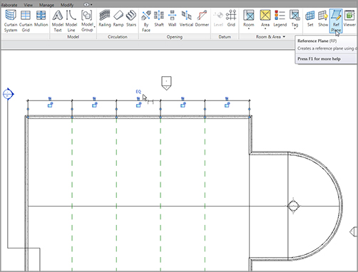
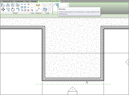
10. Press Esc twice or click Modify. Then, on the Home tab, click Ref Plane, as shown at the top right of Figure 7.10.
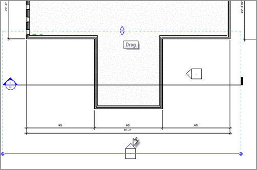
11. Draw four reference planes spaced approximately the same as in Figure 7.10.
12. On the Annotate tab, click the Aligned Dimension button.
13. Add a dimension string starting at the exterior wall to the left and ending at the exterior wall to the right, as shown in Figure 7.10.
14. Click the blue EQ icon. This equally constrains the reference planes.
15. Press Esc twice or click Modify to terminate the command.
16. Select the roof.
FIGURE 7.9 Drawing a new ridge from the two points shown
FIGURE 7.10 Add a dimension string to the reference planes shown here.
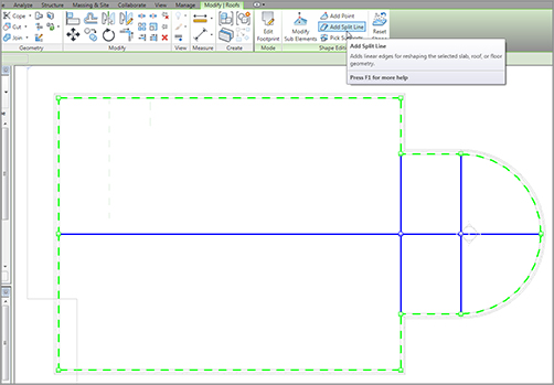
17. Click Add Split Line, as shown in Figure 7.11. Make sure to clear the Chain option.
18. Draw four ridges at the intersections of the reference planes, as shown in Figure 7.11.
FIGURE 7.11 The ridges are in. All that is left is to create some points and start tapering the roof.
19. Press Esc.
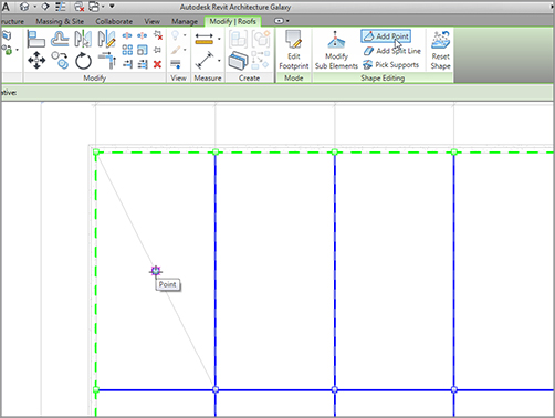
20. On the Annotate tab, click the Detail Line button.
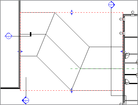
21. Draw a diagonal line from the two points shown in Figure 7.12.
22. Click Modify and then select the roof.
23. Click the Add Point button.
FIGURE 7.12 Add a temporary line, and then pick a point to pitch the insulation to.
24. Pick the midpoint of the diagonal line.
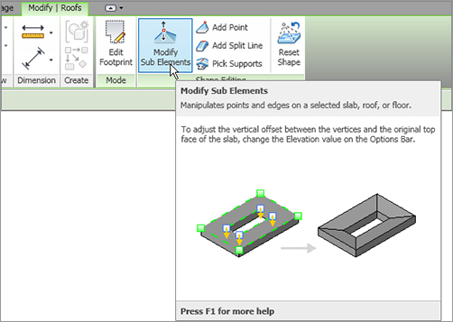
25. Notice that there is a node where you picked the point. To access the node, click the Modify Sub Elements button on the Shape Editing panel, as shown in Figure 7.13.
FIGURE 7.13 Click the Modify Sub Elements button to gain access to the points on the roof.
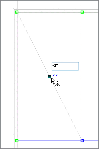
26. Pick the point that you just added. Notice that a blue elevation shows up, as shown in Figure 7.14. Click the elevation, and type -3˝ (-75mm).
FIGURE 7.14 Click here to taper the roof to this point.
27. Press Esc twice.
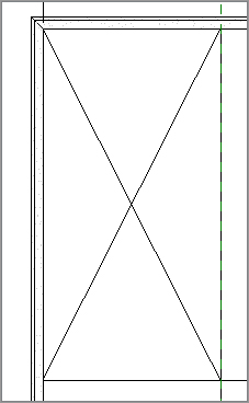
This process tapers the insulation only in this bay, as shown in Figure 7.15. The objective now is to do the same thing for every bay. Because you cannot copy a point, you need to move the temporary line to the next bay and add a new point.
To further investigate how this roof works, and to see the benefits of this approach rather than drafting the lines in, let’s cut a section through the roof and see how the detail looks:
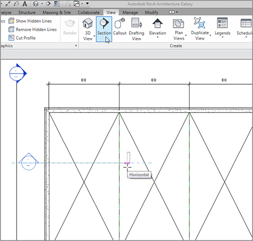
1. On the Create panel of the View tab, click the Section button.
2. Add a section through the roof, as shown in Figure 7.17.
FIGURE 7.17 Adding a section through the roof at this point
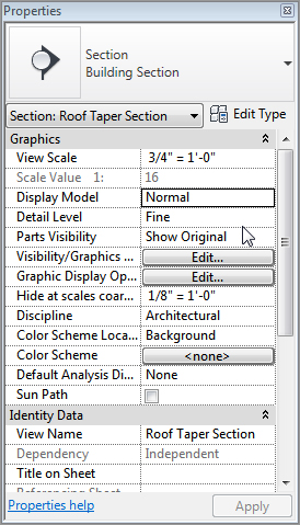
3. In the Type Selector, make sure the type of section is a building section and change View Scale to 3/4˝ = 1´–0˝ (1:20).
4. Change the Detail Level to Fine.
5. Change the View Name option (under Identity Data) to Roof Taper Section (see Figure 7.18).
6. Click the Apply button.
FIGURE 7.18 Changing the properties of the section
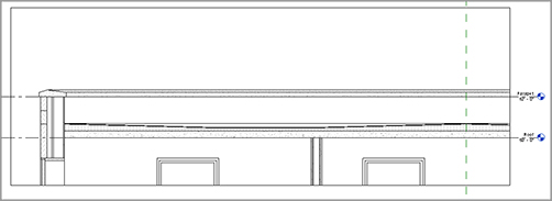
7. Double-click on the section head (or you can find the section called Roof Taper Section in the Project Browser).
8. Adjust the crop region so you are looking only at the roof area, as shown in Figure 7.19.
FIGURE 7.19 By adding the points to the roof, you now have an almost perfect section.
This concludes modeling a flat roof. You can now move on to creating a pitched roof. Again, although these types of roofs can be easy to add in the beginning, more work will be required to get them exactly the way you want them.
Pitched Roofs by Footprint
You’ll add a pitched roof in an identical manner in which you added the flat roof. The only real difference is that each magenta sketch line will need more attention before you finish the sketch. But, after tapering the roof’s insulation, this will be a cakewalk.
You will place the pitched roof over the corridor. The problem with the corridor is that you used a wall system with a parapet cap. This is not the best wall system to receive a pitched roof. First you will change to a simpler wall system:
1. Go to a 3D view of the model.
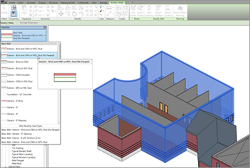
2. Select the six corridor walls, as shown in Figure 7.20.
3. In the Properties dialog box, click the Edit Type button.
4. Click the Duplicate button.
5. Call the new wall system Exterior – Brick and CMU on MTL. Stud (No Parapet).
6. In the Structure row, click the Edit button.
7. In the Edit Assembly dialog box, make sure the Preview button has been selected and the view has been set to Section, as shown at the bottom of Figure 7.21.
8. Click the Sweeps button, as shown in Figure 7.21.
FIGURE 7.21 Without the Preview button selected, you will not be able to modify the parapet sweep.
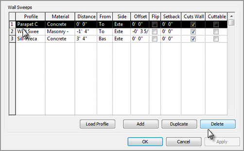
9. In the Wall Sweeps dialog box, you will see three sweeps. The top sweep is the parapet cap. Select sweep 1 (Parapet Cap), and click the Delete button, as shown in Figure 7.22.
10. Click OK three times.
Your corridor walls should look exactly the same but are now void of the concrete parapet cap.
It’s now time to add the roof to the corridor. Because the walls our roof will bear on are now correct, the rest will be a snap!
1. Go to the Level 3 floor plan. (This is the roof level for your corridor.)
2. On the Home tab, choose Roof Roof By Footprint.
3. On the Draw panel, make sure the Pick Walls button is selected.
4. On the Options bar, make sure the Defines Slope button is selected.
5. Type 1 (300mm) in the Overhang field.
6. Pick the six walls that compose the corridor, as shown in Figure 7.23.
With the easy walls out of the way, it is now time to create the gable ends. You should still be in the Pick Walls mode. This is okay, but there are a few things you need to change on the Options bar:
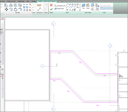
1. Click the Boundary Line button on the Draw panel, as shown in Figure 7.24.
2. On the Draw panel again, click the Pick Lines icon.
3. On the Options bar, deselect Defines Slope.
FIGURE 7.23 Pick these walls for the roof’s footprint.
5. Pick the east wall of the west wing, and the west wall of the east wing, as shown in Figure 7.24.
FIGURE 7.24 You must pick lines to trace the terminating walls of the roof.
It’s cleanup time! Of course the magenta lines are overlapping at the long walls. This is okay—you are an expert at the Trim command by now, especially in Sketch Mode:
1. On the Modify | Create Roof Footprint tab, select the Trim/Extend Single Element command, as shown in Figure 7.25.
2. Trim the intersections that overlap. There are four of them (see Figure 7.25).
FIGURE 7.25 Using the Trim command in conjunction with the roof sketch
3. On the Mode panel, click Finish Edit Mode.
One ugly roof, huh? Welcome to the world of pitched roofs in Revit. You will get the roof you want—you just need to add two roofs here. You will understand this process, but it is going to involve patience and trial and error!
To fix this roof, you simply have to make two separate roofs and join them together. This is a common procedure for the more complicated roof systems in Revit:
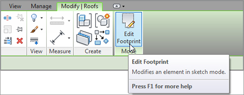
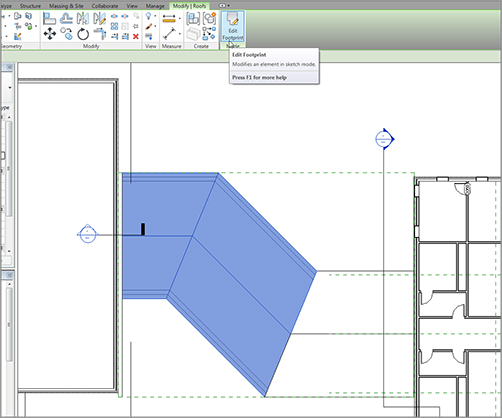
1. Select the roof.
2. On the Modify | Roofs tab, click the Edit Footprint button, as shown in Figure 7.26.
FIGURE 7.26 Selecting the roof and clicking the Edit Footprint button
3. Delete every line, other than the three shown in Figure 7.27.
6. On the Modify | Roofs Edit Footprint tab, click Finish Edit Mode. The roof displays. It still looks funny, but you will take care of that by altering the view range.
7. Start the Roof Roof By Footprint command again on the Home tab. You can also select the roof and click Create Similar on the Modify | Roofs tab that activates.
8. On your own, sketch the roof shown in Figure 7.29. Make sure the lines along the walls are defining a slope. The lines that represent the ends of the roof do not slope.
9. To add the line that matches the roof to the right, make sure you have the Boundary Line button selected on the Draw panel, and that you have Pick Lines selected as well. Now, simply pick the roof to the right, and the line will appear.
10. Review Figure 7.29 to see if your sketch matches. You should have six lines total, and the right and the left ends should not have a slope.
The walls need some help! They are indiscriminately poking up through the roof. You need to do some wall cleanup. First you need to force the walls to use a mitered join at the 45-degree intersections. The following procedure will show you how:
1. Go to the Level 1 floor plan.
2. Zoom in to the wall intersection, as shown in Figure 7.31.
3. On the Modify tab, click the Wall Joins button, as shown in Figure 7.31.
4. Move your cursor over the intersection. You will see a box form around the corner. When you see this box, pick the wall.
5. On the Options bar, click the Miter radio button. Notice that the walls are now joined at a miter.
6. Perform this procedure at all four corners.
You can now attach the tops of the walls to the bottom of the roof:
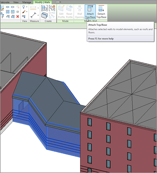
1. Go back to a 3D view and select one of the corridor walls.
2. On the Modify | Walls tab, notice that there is an option to attach the top or base of the wall, as shown in Figure 7.32. Click the Attach Top/Base button.
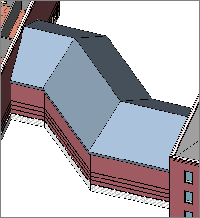
Back in Level 3 (the level in which the corridor roof resides), you are having a view problem: the roof is showing up only to the cut plane for that level. This just cannot be. There is a procedure to correct this called a plan region:
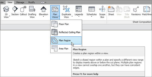
1. Go to the Level 3 floor plan.
2. On the View tab, click the Plan Region button, as shown in Figure 7.34.
3. On the Draw panel, select the Rectangle button, as shown in Figure 7.35.
FIGURE 7.34 Using a plan region enables you to alter the view range in a specified area of a plan.
FIGURE 7.35 Creating the rectangle that forms the perimeter of the plan region
4. Draw a rectangle around the corridor, as shown in Figure 7.35. Be sure to snap to the exact points where the roof meets the taller walls on the east and west wings.
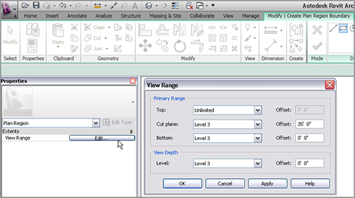
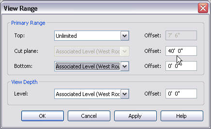
5. In the Properties dialog box, click the Edit button in the View Range row, as shown in Figure 7.36.
FIGURE 7.36 Setting the view range for the plan region
6. In the View Range dialog box, set Top to Unlimited and Level 3 Cut Plane Offset to 35´ 0˝ (11500mm), as shown in Figure 7.36.
7. Click OK.
8. On the Modify | Create Plan Region Boundary tab, click Finish Edit Mode.
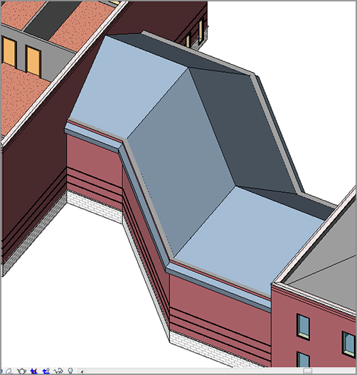
You can now see the roof in its entirety, as shown in Figure 7.37.
There is one more kind of roof to add. It will be a flat roof that has a slope in one single direction. Although you can do this by simply creating a roof with one edge specified as a pitch, at times you will want a roof sloped at an odd direction that can’t be handled by simply angling a roof edge.
To begin the process of creating a sloping roof, you will cap off the west wing of your building. The exterior walls used for the perimeter need to be altered. You are already a pro at this, so let’s start right there:
1. Go to a 3D view.
2. Select the west wing exterior walls, as shown in Figure 7.38.
3. In the Type Selector, select Exterior – Brick And CMU On MTL. Stud (No Parapet), as shown in Figure 7.38.
FIGURE 7.38 Changing the walls to Exterior – Brick And CMU On MTL. Stud (No Parapet)
4. In the Project Browser, go to the West Roof floor plan.
5. On the Home tab, choose Roof Roof By Footprint.
6. On the Draw panel, verify that the Pick Walls button is selected.
7. On the Options bar, deselect Defines Slope.
8. Type 1 (300mm) for the Overhang value.
9. Move your cursor over a wall. Make sure the overhang alignment line is facing outside the walls to the exterior.
10. Press the Tab key on your keyboard. All of the walls are selected.
11. Pick the wall. The magenta lines are completely drawn in. Your sketch should look like Figure 7.39.
Now it is time to set the slope. The objective here is to slope the roof starting at the northeast corner (as the low point) and ending at the southwest corner (the high point). This is done by adding a slope arrow:
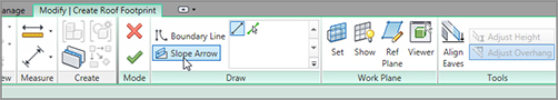
1. On the Draw panel, select the Slope Arrow button, as shown in Figure 7.40.
FIGURE 7.40 Clicking the Slope Arrow button on the Draw panel
2. Pick the corner at the upper right and then the corner at the lower left, as shown in Figure 7.41.
Of course, there is a wall issue. You can attach most of the walls to the roof simply by selecting them and attaching the tops. You will, however, have to modify the profile for one wall:
1. In the 3D view, select all of the exterior west wing walls, excluding the one on the east side that is west of the corridor (you can see it in Figure 7.45).
2. On the Modify | Walls tab, select Attach Top/Base.
3. Pick Top from the Options bar (it is all the way to the left).
5. In the Project Browser, go to the section called West Corridor Section.
6. Select the wall that does not attach to the roof.
7. On the Mode panel, click Edit Profile.
FIGURE 7.45 Attaching the tops of the walls to the sloping roof
8. Trace the roof with the line tool. Be sure you delete the magenta line that established the top of the wall.
9. On the Sketch tab, click Finish Edit Mode. You now have all of the walls joined to the roof. Right now would be a good time to check out the roof in 3D just to make sure the results are pleasing to you.
10. Save the model.
The next item to tackle will be creating a roof by extrusion. This is where you can design a custom roof.
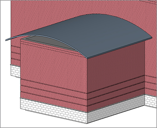
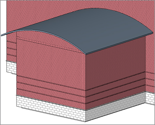
Creating a roof by extrusion is almost always done in an elevation or a section view. The concept here is to create unique geometry that cannot be accomplished by simply using a footprint in a plan. A barrel vault or an eyebrow dormer comes to mind, but there are literally thousands of combinations that will influence how our roofs will be designed.
To get started, the last roof left to be placed is the south jog in the west wing of the model. This is the perfect area for a funky roof!
The first thing to do is to change the three walls defining the jog to the Exterior – Brick And CMU On MTL. Stud (No Parapet) wall type:
1. Go to a 3D view.
2. Select the three walls that compose the jog in the south wall, as shown in Figure 7.46.
3. From the Properties dialog box, switch these walls to Exterior – Brick And CMU On MTL. Stud (No Parapet), as shown in Figure 7.46.
FIGURE 7.46 Changing the wall types as you have been doing all along
4. Go to the Level 1 floor plan.
5. On the View tab, select the Elevation button.
6. In the Properties dialog box, be sure the elevation is a Building elevation (you are given the choice in the drop-down menu at the top of the dialog box).
14. On the Home tab, select the Ref Plane button; then, in the Draw panel, click the Pick Lines button.
15. Set Offset to 1´–6˝ (450mm).
16. Pick the southernmost wall and offset the reference plane away from the building (see Figure 7.48).
17. Press Esc twice or Click Modify to clear the command.
18. Select the reference plane.
19. In the Properties dialog box, change the name to South Entry Overhang.
20. Click the Apply button.
21. Open the elevation called South Entry Elevation.
The importance of that reference plane you just added becomes obvious at this point. You needed to establish a clear starting point for the roof you are about to add. Because the roof will be added in an elevation, Revit does not know where to start the extrusion. This reference plane will serve as that starting point.
1. On the Home tab, choose Roof Roof By Extrusion, as shown in Figure 7.49.
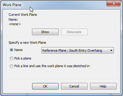
2. When you start the command, Revit will ask you to specify a reference plane. Select Reference Plane: South Entry Overhang from the Name drop-down list, as shown in Figure 7.50.
FIGURE 7.50 Selecting the South Entry Overhang reference plane
3. Click OK.
4. In the next dialog box, change the Level setting to Level 3, and click OK.
5. In the Home tab, select Reference Plane, as shown in Figure 7.51, and then click the Pick Lines button.
6. Offset a reference plane 3´–0˝ (900mm) to the left and to the right of the exterior walls, as shown by numbers 1 and 2 in Figure 7.51.
7. Offset a reference plane 4´–0˝ (1200mm) up from the top of the wall, as shown by number 3 in Figure 7.51.
8. In the Properties dialog box, select Roofs from the drop-down list, and then click the Edit Type button.
9. Click Duplicate.
10. Change the name from Generic – 12˝ 2 to Canopy Roof.
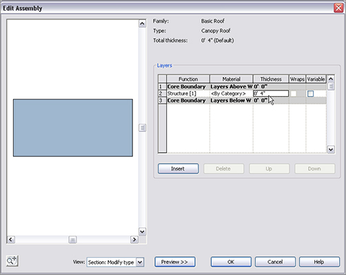
11. Click the Edit button in the Structure row.
12. In the Edit Assembly dialog box, change the structure thickness to 4˝ (100mm), as shown in Figure 7.52.
13. Click OK twice to get back to the model.
FIGURE 7.51 Adding reference planes to use as construction lines
FIGURE 7.52 Changing the thickness of the canopy roof
Now it’s time to put the actual roof into the model. So far you have been using great discipline in terms of setting reference planes and creating a separate roof for this canopy. Try to make this a habit!
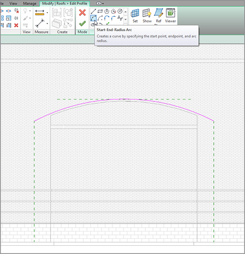
1. On the Draw panel of the Modify | Create Extrusion Roof Profile tab, click the Start-End-Radius Arc button, as shown in Figure 7.53.
2. Draw an arc from the points shown in Figure 7.53.
FIGURE 7.53 Drawing an arc, which will define the outside face of the roof
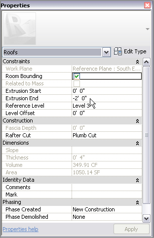
3. In the Properties dialog box, set Extrusion End to -2´–0˝ (-600mm), as shown in Figure 7.54.
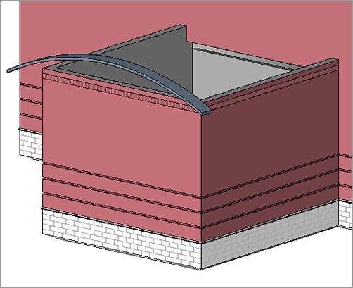
The walls are now joined to the roof, as shown in Figure 7.58.
FIGURE 7.58 The walls are now attached to the roof.
All of the conventional roofing systems have been added. It is now time to move on to adding some dormers. This process will simply use a collection of the tools you have gained experience with up to this point.
The best way to add a roof dormer is to modify an existing roof. You certainly have plenty of those in this model, so there should be no shortage of roof surfaces you can use to chop up into dormers.
To begin adding a roof dormer, follow along:
1. Go to the Level 3 floor plan.
2. Zoom in on the corridor roof.
3. Select the corridor roof, as shown in Figure 7.59.
4. On the Modify | Roofs tab, click the Edit Footprint button.
4. The two points are an even 4´–0˝ (1200mm) in from each edge.
5. Press Esc twice.
6. Select the middle line.
7. On the Options bar, deselect Defines Slope.
Now that the length of the dormer has been established, you need to indicate to Revit that you want it to be a gable-end dormer. You do this by adding slope arrows:
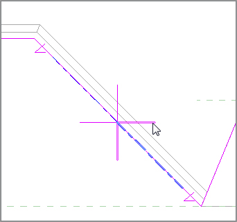
1. On the Draw panel, click the Slope Arrow button.
2. For the first point of the slope arrow, click the endpoint of the first point you split (see number 1 in Figure 7.61).
3. For the second point of the slope arrow, pick the midpoint of the middle line (see Figure 7.61).
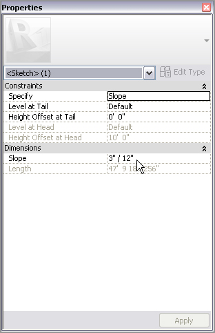
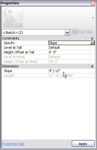
7. In the Properties dialog box, under Constraints, change Specify to Slope.
8. Under Dimensions, keep the slope at 9˝ / 12˝ (750 / 1000mm) (see Figure 7.63).
FIGURE 7.63 Changing the values of the slope arrows
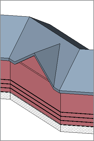
9. Click Finish Edit Mode.
10. Go to a 3D view to check out the dormer. It should look identical to Figure 7.64.
Adding roof dormers takes some practice to become efficient. If you do not feel confident that you can do a roof dormer on your own, feel free to either go back through the procedure or find another place in the building to add a second dormer.