Well, we can’t avoid the topic of structure forever. Because we need to consider our structure from pretty much the beginning of the project, I had better add it to the first half of the book before we get too carried away!
Revit has entire books on this subject alone, so this book addresses only the structural items available to people using Revit Architecture. If you are a structural engineer or structural designer, I recommend that you use Revit Structure. That application is just as powerful as Revit Architecture but is geared toward structural engineering. That being said, the two applications share the same file extension (.rvt), which you can open and modify directly from either Revit Architecture, Revit Structure, or Revit MEP with absolutely no issues.
This chapter delves into the structural world by presenting available functions that have been blended in with the architectural tools. The first item you will tackle is usually the first item in the model: structural grids. Although you add structural grids line by line, you will soon discover that these grids are just as “smart” as the rest of Revit. The starting point for all things structural is most certainly the grid. In Revit Architecture, you will find quickly that placing a structural grid into a model is not a complicated task. Grids are essentially placed one line at a time. Those lines you place, however, have “intelligence.” For example, if you place a vertical grid line called A and then place a horizontal grid line called 1 that intersects with A, you will have a grid location. If you place a column at that intersection, the column will assume a new property called Location. That location is—you guessed it—A-1.
Let’s get started. To begin, open the file you have been following along with. If you did not complete the previous chapter, go to the book’s web page at www.sybex.com/go/revit2012ner. From there you can browse to Chapter 8 and find the file called NER-19.rvt.
Placing a Grid
Placing a grid means drawing grid lines in one by one. You can copy grids to speed up placement, and array them if the spacing is regular. This task sounds tedious, but it is a welcome change from other applications that force you to create an entire, rectangular grid that you have to keep picking at until it resembles your layout. Grids are like snowflakes: no two are the same.
1. In the Project Browser, go to the Level 1 floor plan. (Make sure you aren’t in the Level 1 ceiling plan.)
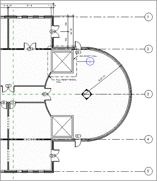
2. Zoom in to the east wing’s radial entry.
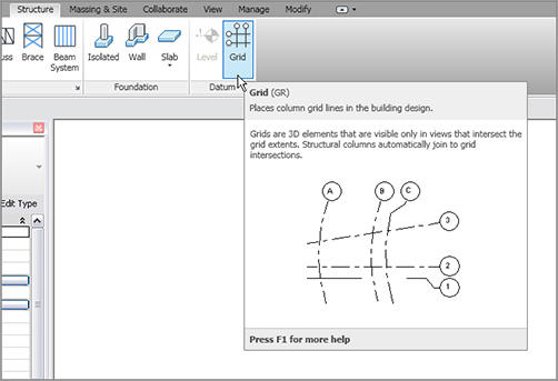
3. The Datum panel that holds the Level and Grid tools appears on the Home tab and the Structure tab. On the Datum panel of the Structure tab, click the Grid button, as shown in Figure 8.1.
FIGURE 8.1 The Grid button on the Datum panel of the Structure tab
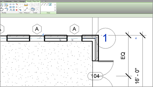
4. On the Draw panel of the Modify | Place Grid tab, click the Pick Lines icon, as shown in Figure 8.2.
5. Pick the core centerline of the north wall, as shown in Figure 8.2.
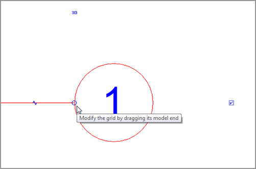
6. The grid bubble needs to be moved. Press Esc twice or click Modify (to clear the command), and select the grid bubble. Notice the round blue grip, similar to Figure 8.3.
11. Drag the right end of the line to align with grid 1. It snaps weakly. After you move your line to the length of grid 1, pick the second point. An alignment line appears.
12. If the grid bubble isn’t appearing on the right side as shown, but on the left side, find the blue box on the right side of grid 2. Pick it. It will turn the grid head on.
13. On the left side of grid 2, you will see a grid bubble (see Figure 8.5). You will also see the same blue check box. Click the check box to turn the grid head off at this location.
14. Press Esc.
Being able to pick lines is certainly an advantage, but you will not always be in a situation where you have geometry in place to do so. In the following procedure, you will add grid 3 by picking two points:
1. Select the Grid button from the Home tab.
2. On the Draw panel, select the Line icon.
3. Pick a point along the center reference plane, as shown in Figure 8.6.
4. Pick a second point in alignment with grid 2 (see Figure 8.6).
FIGURE 8.6 Adding grid 3 at the center of the building
5. Add grids 4 and 5 to the exact opposite ends of the east wing (see Figure 8.7).
You need to add two more grids at 45-degree angles. This will be as easy as drawing lines. The objective here is to manipulate the grids to read the appropriate numbering:
1. On the Home tab, click the Grid button if it’s not selected already.
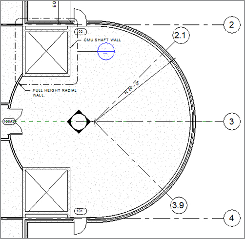
2. Pick the center of the radial wall.
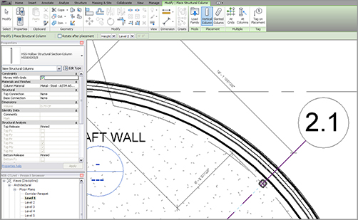
3. Draw the line at a 45-degree angle until you are beyond the radial wall, as shown in Figure 8.8.
4. Click in the bubble for the angled grid and rename the grid line 2.1. You can do this while placing grids. Click outside the grid number field to enter the change.
5. Draw another grid line at a 45-degree angle in the opposite direction.
FIGURE 8.8 Adding two additional grids and renumbering them
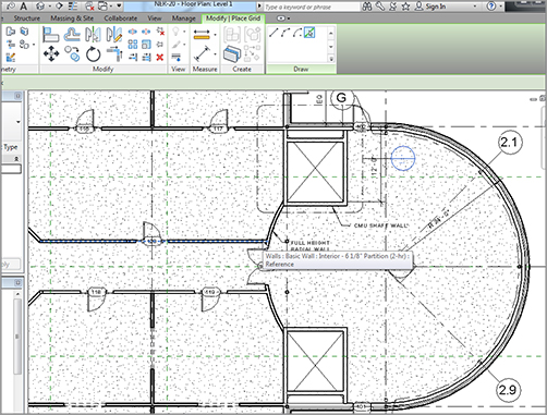
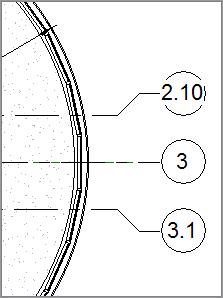
You need two more horizontal column lines that span the length of the building. You will number these lines as 2.10 and 3.1. The lines will run centered on the corridor walls. To do this, you will use the Pick Lines icon on the Draw panel.
1. On the Home tab, click the Grid button if it’s not selected already.
2. On the Draw panel, click the Pick Lines icon.
3. Pick the core centerline of the north corridor wall, as shown in Figure 8.9.
FIGURE 8.9 Adding a column line to the north corridor wall
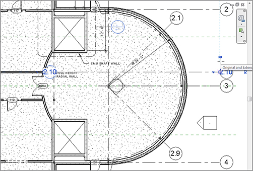
4. Pick the blue grip at the end of the line and stretch it to align with the already placed bubbles, as shown in Figure 8.10.
FIGURE 8.10 Dragging the line and turning on the bubble so you can rename the grid to 2.10
7. Zoom to the other end of the grid line and deselect the Show Bubble check box if necessary.
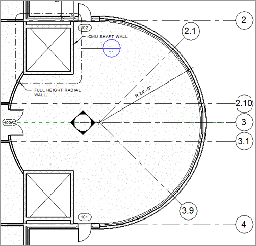
8. Repeat the process for the south corridor wall, adding an additional grid line numbered 3.1, as shown in Figure 8.11.
The grids are laying out okay, but it looks like you should make some adjustments to move the bubbles apart a little. You can do this by adding an elbow to the grid’s end.
Adding Elbows
As with levels, you can add a break in the line of the grid, allowing you to make adjustments as if the grid were an arm with an elbow:
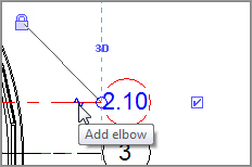
1. Click Modify. Select grid 2.10.
2. You will see several blue grips appear. Pick the one that appears as a break line, as shown in Figure 8.12.
FIGURE 8.11 Adding the grids along the corridor walls
FIGURE 8.12 Clicking the Add Elbow grip after selecting the grid
3. When you pick this break line, it adds an elbow to your grid line, as shown in Figure 8.13.
4. Repeat the procedure for grid 3.1. Your grids should now look like Figure 8.13.
It is now time to add the vertical grids. This will be a simple process until you get to the radial entry area. At that point, there will need to be some additional manipulating of the grid.
Adding Vertical Grids
The only real issue with adding vertical grids is the numbering versus lettering issue, because Revit will continue the sequencing from the horizontal grids. Make sure that when you add your first grid going in the opposite direction, you renumber (or rename) the first occurrence of the grid.
The objective of the next procedure is to create a grid pattern running vertically across the view:
1. Zoom out so you can see the entire east wing, as shown in Figure 8.14.
2. On the Datum panel of the Home tab, click the Grid button.
3. On the Draw panel of the Modify | Place Grid tab, click the Pick Lines icon, as shown in Figure 8.14.
4. Pick the core centerline of the west exterior wall of the east wing, as shown in Figure 8.14.
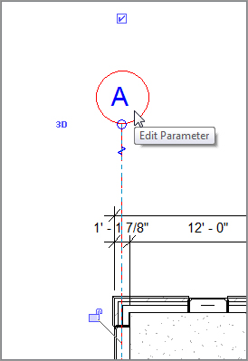
5. When you pick the wall, the grid is added. It will not be the name or number you want. You will change that. But first, pick the round blue grip and drag the bubble up past the dimensions, as shown in Figure 8.15.
6. Press Esc.
7. Select the new vertical grid.
8. Click in the bubble and rename it to A, as shown in Figure 8.16.
FIGURE 8.14 Adding the first vertical grid by picking the core centerline of the exterior wall
FIGURE 8.15 Dragging the new bubble out of the wall
It is now time to duplicate this grid. Because you have an arsenal of modify commands under your belt, the best way to duplicate this grid is to copy it, as shown in the following steps:
1. Select grid A.
2. On the Modify | Grids tab, click the Copy button, as shown at the top of Figure 8.17.
3. On the Options bar, make sure the Multiple check box is selected, as shown near the top left of Figure 8.17.
4. Pick a base point along the grid line within the wall, as shown in Figure 8.17.
5. Copy grid A to the wall centerlines, as shown in Figure 8.17. Notice that the grid lines will auto-sequence as you go.
6. Press Esc twice.
7. Start the Grid command again.
8. On the Draw panel, be sure the Line button is selected.
9. Pick a start point at the endpoint of the radial wall, where it intersects with the straight wall, as shown near the bottom of Figure 8.18.
10. Pick the second point in line with the adjacent grid bubbles (see Figure 8.18).
FIGURE 8.17 Copying the grid line to the other walls
12. Pick the grip on the bottom of the line, and drag it down past the south part of the radial wall.
The next step is to add the grid to the radial entry area. This will not be as easy as simply picking a wall’s centerline. The trick here will be to establish a reference point to place the grid and, subsequently, a column.
Adding a Radial Grid Line
Sometimes, you have to think outside the box. Literally. Because you have radial geometry to contend with, you need to add a radial grid, as follows:
1. Zoom in on the radial entry of the east wing.
2. Click the Grid button on the Home tab if the grid command is not currently running.
3. On the Draw panel, select the Pick Lines button, as shown in Figure 8.19.
FIGURE 8.19 Adding a grid line offset from the finish inside face
4. Type in an offset of 6˝ (150mm) on the Options bar.
5. Pick the finished, inside face of the radial wall, as shown in Figure 8.19. Make sure the alignment line indicating where the grid will go is on the inside of the wall.
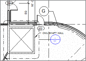
6. The actual grid bubble lands in a congested area. Fix this by adding an elbow and adjusting the bubbles, as shown by grid G near the top of Figure 8.20.
FIGURE 8.20 Adding bubbles to the radial grid line and adjusting their placements with elbows
One last thing you need to do is to make sure the grids are extending all the way to the west side of the east building. This will play a major role when you start placing columns.
1. Select grid 1.
2. Pick the grip icon to the left of the grid line.
3. Drag the grid past the west wall.
4. Repeat the procedure for grids 2, 2.10, 3.1, 4, and 5.
5. Repeat the procedure, stretching the vertical grids south. This will include grids A, B, C, D, and E. If you drag the lower end of grid A down, the copied grids B, C, D, and E will move with it. Make the lower end of grid F snap into alignment with the others.
I think you get the picture on adding grids. The next procedure is to start adding columns to these grid intersections. To do so, you will explore the Structure tab on the Ribbon.
The hard part is over. Determining where to put the columns is harder than physically placing them in the model. But of course there are rules to follow, and rules that need to be bent in order to accomplish the results you want to see.
This next series of procedures includes adding structural components to the model and placing framing systems in areas where a structural engineer may defer to the architect for structural integrity, given the design intent. (Also, try using that phrase in a meeting).
To add columns to the model, follow this procedure:
1. In the Project Browser, go to the Level 1 floor plan.
2. Zoom in to the radial entry area in the east wing.
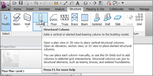
3. On the Structure tab, click Column Structural Column, as shown in Figure 8.21. This tool is also on the Home tab.
FIGURE 8.21 The Structural Column button on the Structure tab of the Ribbon
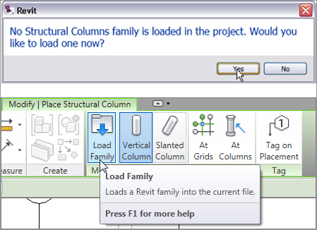
4. You will probably not have any structural columns loaded into the model. If you get the message shown in Figure 8.22, click Yes to browse for a structural column. If you do have a column, click the Load Family button.
5. Browse to US Imperial Structural Columns Steel (or Metric Structural Columns Steel).
FIGURE 8.22 You’ll see this message when no structural columns are loaded in the model. Click Yes. You can click the Load Family button to add additional columns to your project.
6. In the Steel folder, browse to HSS-Hollow Structural Section-Column.rfa (or M_HSS-Hollow Structural Column.rfa).
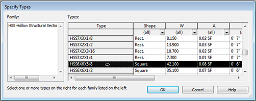
7. Double-click HSS-Hollow Structural Section-Column.rfa (or M_HSS-Hollow Structural Column.rfa). You will see a dialog box enabling you to select the type, as shown in Figure 8.23.
FIGURE 8.23 Select HSS-Hollow Structural Section-Column.rfa and choose the HSS6×6×5/8 (HSS152.4×152.4×12.7) type.
8. Select the HSS6×6×5/8 (HSS152.4×152.4×12.7) column.
9. Click OK.
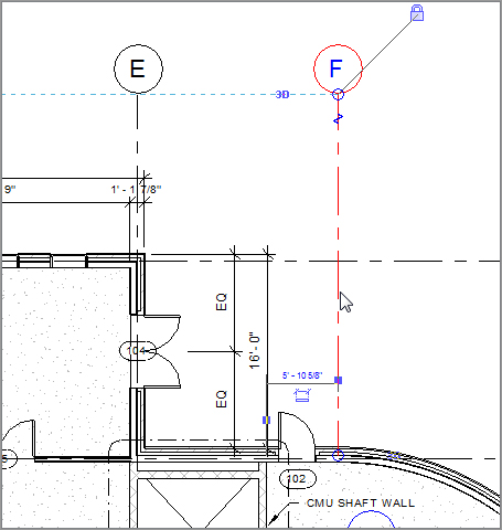
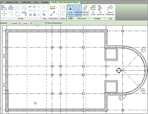
10. On the Options bar, make sure Height is set to Roof, as shown in Figure 8.24.
FIGURE 8.24 Placing the column on grid intersection F-1
11. Place the column on the grid intersection F-1.
12. Press Esc twice.
13. Click the Column Structural Column button on the Home tab.
14. Place a column at grid intersection F-2. Before you place this column, be sure Height is set to Level 2.
15. Set the column height Option to Roof. Place another column at grid intersection F-G (see Figure 8.25).
16. Click Modify.
17. Select the column you just placed (column F-G).
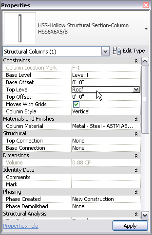
18. In the Properties dialog box, make sure that the top level is set to Up To: Roof, as shown in Figure 8.26 (just to check).
FIGURE 8.26 Setting the column’s Top Level to extend to the roof
19. Mirror the three columns to the opposite side of the entry, using column line 3 as the reference plane.
20. Save the model.
It’s time to start adding some full-height columns at the rest of the grid locations. You will begin with the radial grid, and then place the rest of the columns in the walls of the exterior and the corridor:
1. On the Structure tab, click the Column Structural Column button.
2. On the Options bar, be sure Height is set to Roof.
3. Hover your cursor over grid intersection G-2.1. Notice that you can see the column, but it is at the wrong orientation.
4. Press the Tab key on your keyboard, and the column will rotate to align with the grid, as shown in Figure 8.27.
5. When the column is aligned, pick the intersection. The column is placed.
6. Repeat the steps for columns 3 and 3.9.
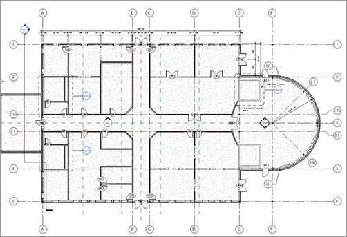
It’s time now to start placing columns in the main part of the wing. Place a column at every grid location. Note that you must stretch the column lines to the left side of the wing. You should also turn the grid bubbles on at the west and south sides of the building, as shown in Figure 8.28.
FIGURE 8.28 The grids should be extended and the bubbles turned on at each end.
To add columns by intersection, follow these steps:
1. Start the Structural Column command.
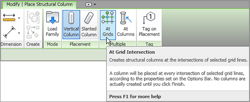
2. On the Modify | Place Structural Column tab, click the At Grids button on the Multiple panel, as shown in Figure 8.29.
FIGURE 8.29 Using the Place Column At Grids function
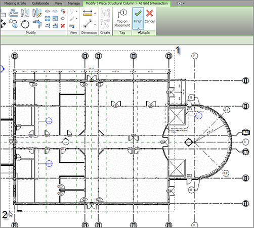
3. Pick a window around the rectangular portion of the east wing (from right to left), as shown in Figure 8.30.
4. Notice that the Modify | Place Structural Column At Grid Intersection tab now changes to allow you to either finish or cancel. After you have the window placed, click the Finish button on the Multiple panel, as shown at the top of Figure 8.30.
5. Press Esc.
FIGURE 8.30 Picking a window where the columns will be placed
There are quite a few columns placed. You will need to move some of these columns, including the four columns in the corridor intersection area. Revit will still locate these columns at a grid intersection, except it will add the offset in the column’s properties.
To move the columns and create a column offset, follow these steps:
1. Zoom in to the middle of the east wing at the corridor intersection.
2. Select the two columns at the left of the corridor, as shown in Figure 8.31.
3. Move the columns 4´–0˝ (1200mm) to the left (see Figure 8.31).
FIGURE 8.31 Moving the columns to the left 4´–0˝ (1200mm)
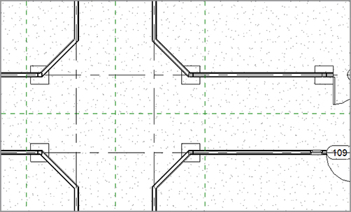
4. Repeat the same procedure for the other two columns (see Figure 8.32).
FIGURE 8.32 Making adjustments such as moving a column will happen quite a bit.
7. Thank your structural engineer for allowing this. She is extremely understanding.
8. Save the model.
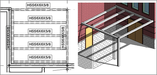
That’s enough columns for now. It’s time to move on to adding some structural framing. The main areas where you will add framing are in the canopy areas surrounding the east entry of the east wing.
Although you will not create much structural framing in Revit Architecture, there are a few areas where you will need to add some framing. Canopies with light structural framing are certainly one area that could call for the architect to wander over to the structural side of the fence.
To start adding structural framing:
1. In the Project Browser, go to the Level 2 floor plan.
2. Zoom in to the radial entry area.
3. Select columns F-1 and F-5.
4. In the Properties dialog box, set the Top Level to Level 2. (This makes the columns disappear for a moment.)
5. Set the Properties display to Floor Plan: Level 2.
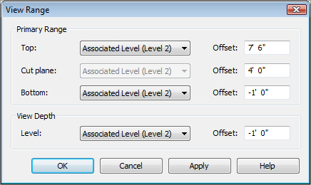
6. In the Properties dialog box, scroll down to the View Range row, and click the Edit button.
7. In Primary Range, set Bottom Offset to -1´–0˝(-300mm).
8. For View Depth, set Level Offset to -1´–0˝(-300mm), as shown in Figure 8.33.
FIGURE 8.33 Setting the view range so you can see below the level
9. Click OK. You can now see the column.
It is now time to place the structural framing. Make sure you are zoomed in to the northeast corner of the east wing.
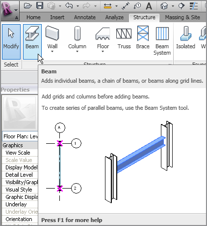
1. On the Structure panel of the Structure tab, select the Beam button, as shown in Figure 8.34.
FIGURE 8.34 The Beam button on the Structure panel of the Structure tab
2. If you get a message stating that no structural framing family is loaded into the model, click Yes. If you don’t, click the Load Family button.
11. Draw a beam 6˝ (150mm) off the finish face of the wall, starting at the top beam and ending on column line 2, as shown in Figure 8.37. (This will later be supported by the framing within the building).
FIGURE 8.37 Adding a beam 6˝ (150mm) off the face of the wall to column line 2
12. Draw another beam from the left to the right, 6˝ (150mm) off the finish face of the wall, as shown in Figure 8.38.
It is now time to add some filler beams. In Revit Architecture, you can add a beam system that is controlled by a specified spacing. After the system is in place, you can control the properties for the duration of the project.
Adding a Beam System
Although adding beam systems is much more crucial in Revit Structure, it does have its usefulness in Revit Architecture as well. Having the capability to equally space a framing system can be quite advantageous.
To create a beam system, follow along with this procedure:
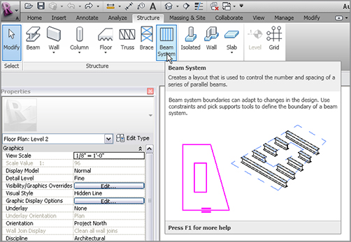
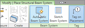
1. On the Structure panel of the Structure tab, click the Beam System button, as shown in Figure 8.39.
2. Make sure the Automatic Beam System button is picked, as shown in Figure 8.40.
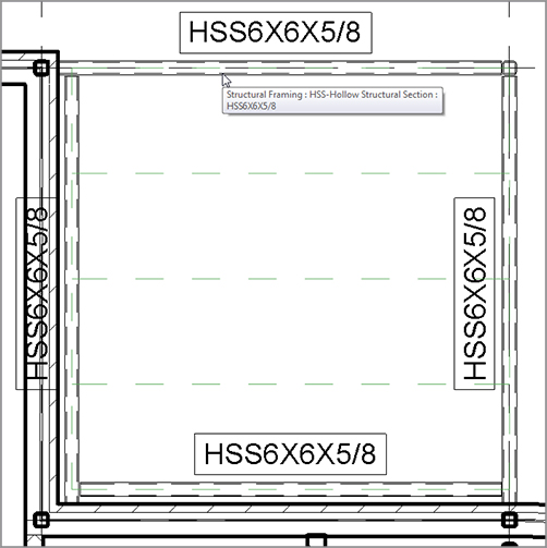
3. On the Options bar, make sur HSS6×6×5/8 (HSS152.4×152.4×12.7) is the Beam Type selection.
4. Change the Layout Rule to Maximum Spacing, as shown in Figure 8.41. Set the distance field to 4´–0˝ (1200mm).
8. Click Modify. Mirror the canopy to the other side of the radial entry. Be careful not to accidentally mirror the columns.
9. You may receive the same message about bearing a structural member on a nonstructural wall. Click the Make Wall Bearing button.
By using the Beam System command, you can easily add multiple occurrences of framing members quite quickly. In some cases, however, you will need nonuniform members on a different plane, such as lateral bracing.
Adding Bracing
It would be nice to add a rod to the top of this canopy at an angle. You can accomplish this by using the Brace command.
To use the Brace command, let’s first add the rod family to our model:
1. To load the rod family, click the Load Family button on the Insert tab.
2. Browse to Structural Framing Steel, and open the file called Round Bar.rfa (or M_Round Bar.rfa).
3. Now that the file is loaded, go to the North elevation in the Project Browser. Notice that grid lines A–F are visible in this view—very useful!
4. In the Properties panel for the North elevation, change Detail Level to Fine and Visual Style to Shaded.
5. Zoom in on the east canopy.
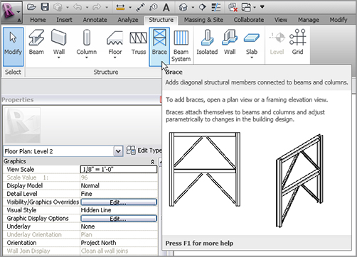
6. On the Structure panel of the Structure tab, click the Brace button, as shown in Figure 8.44.
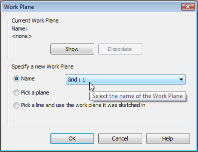
7. After you select the Brace button, Revit displays a dialog box asking you to specify a work plane. In the Name drop-down list, select Grid : 1, as shown in Figure 8.45, and then click OK.
FIGURE 8.45 Specifying Grid : 1 as the work plane for the bracing
8. Verify that Round Bar: 1˝ (M_Round Bar 25mm) is the current framing member in the Type Selector.
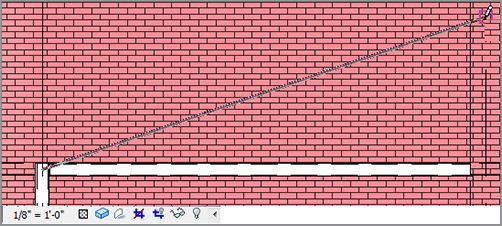
15. Mirror the rods to the other canopy. You can stay in the East elevation to do so.
16. Save the model.
That pretty much covers it for framing. The next section will bring you underground into the foundation. Although the structural engineer will usually specify the foundation system, architects must have access to foundation tools to place concrete foundation walls as well as to strip and isolate footings and piers. The next section addresses these topics.
The first question that arises while addressing structural foundations is, “What if the architect places a foundation in the model, and then the structural engineer places one in their model?”
What will happen is the structural engineer will use a method called Copy/Monitor, whereby the engineer takes the architect’s foundation and makes it their own. The engineer is then free to alter the foundation. This method is addressed fully in Chapter 20, “Importing and Coordinating Revit Models.”
This section focuses on creating foundation walls. Although adding this type of wall is similar to adding architectural walls, there are a few things you want to look out for.
For now, let’s add a foundation and deal with coordination later. The task before you here is to create a foundation wall constructed of 18˝ (450mm) of solid concrete. To proceed, follow these steps:
1. Go to the Level 1 floor plan.
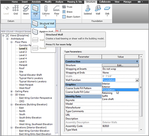
2. Click the Wall Structural Wall button on the Structure tab, as shown in Figure 8.48.
3. In the change Type Selector, select Generic 8˝ Masonry (Generic – 200mm).
4. Click the Edit Type button.
5. Click the Duplicate button.
6. Name the new wall 18˝ Concrete (450mm Concrete).
7. Click OK.
8. In the Wall Function row, select Foundation from the drop-down list, as shown in Figure 8.48.
9. Just under the Wall Function row is the Coarse Scale Fill Pattern row. Change the hatch to Concrete by clicking the […] button and selecting Concrete from the menu. Click OK.
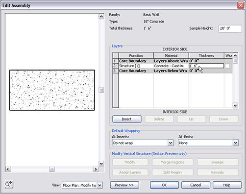
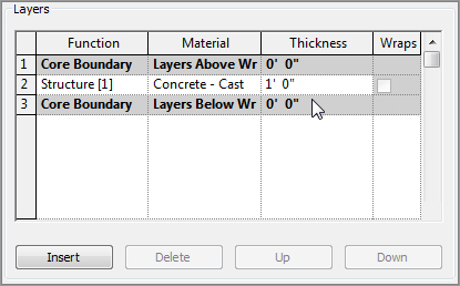
10. Click the Edit button in the Structure row.
11. In the second row in the Layers chart, click in the Material cell.
15. Change the Thickness to 1´–6˝ (450mm), as shown in Figure 8.49.
16. Click OK twice.
You are about to place a wall underneath this level. This view is currently set to not show anything below this level, forcing us to alter the view range.
FIGURE 8.49 Changing the Material and Thickness settings
To modify the view range, follow these steps:
1. Set the Properties to Floor Plan: Level 1. Scroll down to View Range and click the Edit button.
2. For Primary Range, set Bottom Offset to -1´–0˝ (-300mm).
3. For View Depth, set Level Offset to -1´–0˝ (-300mm).
4. Click OK.
5. On the Draw panel, click the Pick Lines icon.
6. Foundation walls are placed top down, so there is Depth rather than Height on the Options bar. Make sure that Depth is set to T.O. Footing on the Options bar, and make sure the justification is set to Wall Centerline.
7. Pick the core centerline of the exterior wall, as shown in Figure 8.50.
FIGURE 8.50 Picking the core centerline of every exterior wall in the entire model. This includes the corridor and both wings.
8. Keep repeating picking the exterior walls in all three sections of the model.
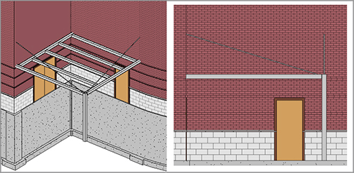
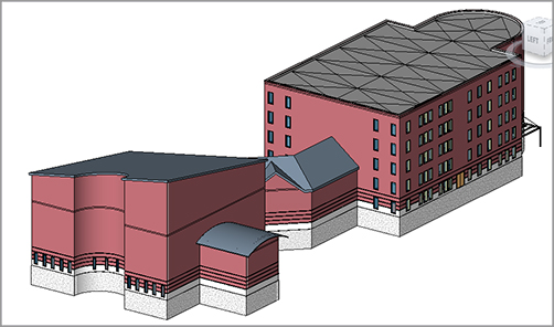
Your 3D model should look like Figure 8.51. Get into the habit of viewing the model in 3D—especially when you can’t see exactly where the walls are being placed in the plan.
Now you can travel into the ground and check out how your walls are joining. Some cleanup will be involved:
1. In the Project Browser, find the T.O. Footing floor plan and double-click it.
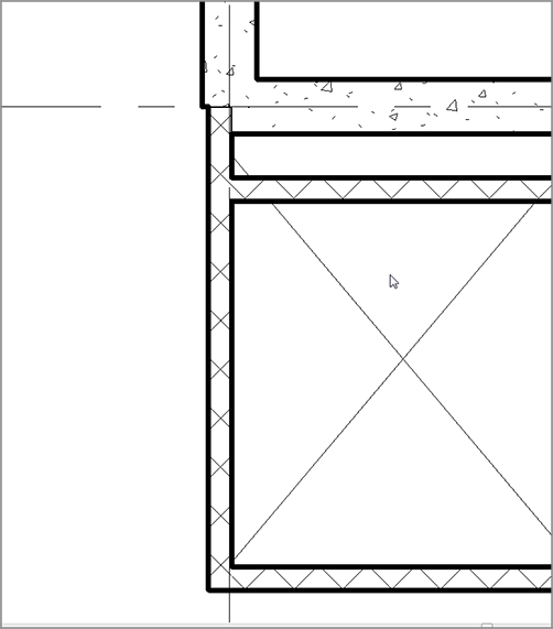
2. Zoom in to the east wing area, where the north elevator meets the foundation wall. There is an issue: the walls are funky, as shown in Figure 8.52.
3. Select the left masonry elevator shaft wall.
4. Drag the wall out so it abuts the foundation wall.
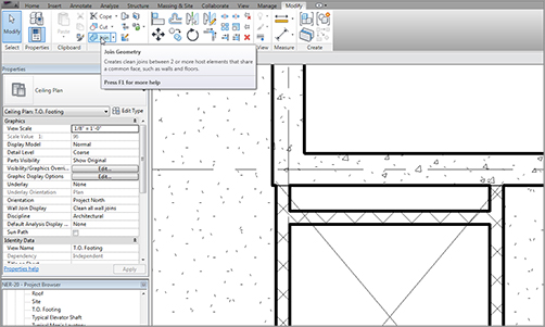
5. The masonry wall to the right needs to be joined to the foundation wall. To do this, click the Join Geometry button on the Modify toolbar, as shown in Figure 8.53.
6. Pick the foundation wall.
7. Pick the masonry wall. The masonry wall is now notched back for the foundation.
FIGURE 8.52 The walls are not behaving as we would like them to.
8. Repeat the procedure for the south elevator. The condition may be slightly different from that of the north elevator, but the process to fix it will be the same.
Moving to the west wing, there is one wall you need to fix. The command you will have to use is the Split command:
2. On the Modify tab, click the Split Element button, as shown in Figure 8.54.
3. On the Options bar, click the Delete Inner Segment check box (see Figure 8.54).
4. Pick the points labeled 1 and 2, shown in Figure 8.54.
FIGURE 8.53 Joining the walls will enable the foundation walls to terminate as expected.
FIGURE 8.54 Splitting the foundation wall to follow the profile of the wall above
Now that the foundation walls are in place, it is time to think about what these walls are bearing on. Revit Architecture has tools to add footings to the bottom of these walls.
If you are going as far as placing structural foundation walls, you might as well continue on and place footings underneath them, right? Luckily, this is not a difficult task.
Before you start adding the structural footings to the plan, you need to acknowledge that, by default, this view is not set up to see any objects that are physically below its level. To correct this, you must alter the view range of this specific plan:
1. Make sure you are still in the T.O. Footing plan, and set the Properties list to Floor Plan: T.O. Footing.
2. In the Properties dialog box, go to the View Range row and click Edit.
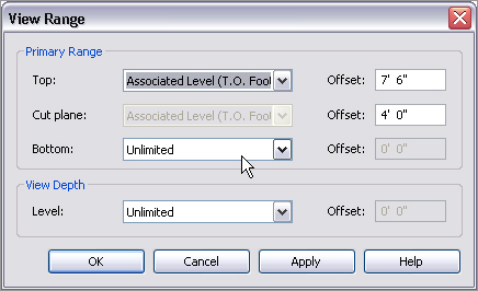
3. Set Primary Range Bottom to Unlimited.
4. Set View Depth Level to Unlimited, as shown in Figure 8.55.
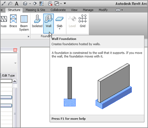
6. On the Foundation panel of the Structure tab, click the Wall Foundation button, as shown in Figure 8.56.
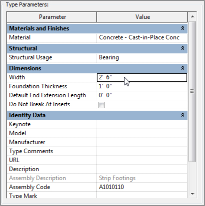
At the top of the Properties dialog box, notice it says Bearing Footing – 36˝ × 12˝ (900mm × 300mm). This is a little big for our purposes, so let’s make a new one:
1. In the Properties dialog box, click the Edit Type button.
2. Click Duplicate.
3. Call the new footing element Bearing Footing – 30˝ ×12˝. (Metric users will call it Bearing Footing – 750mm × 300mm).
7. Start picking walls. This footing will be centered underneath each wall you pick. Ignore the elevator shaft walls.
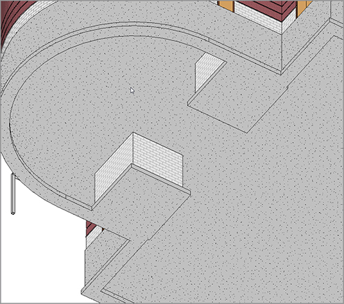
8. When you are finished picking the walls, go to a 3D view to make sure you have all of the foundations covered, as shown in Figure 8.58.
FIGURE 8.58 Doing a 3D investigation to see whether the footings are all in place
When all the footings are in place, you can see that you need to focus on the elevator shafts. Because you need an entire foundation mat underneath the elevators, you can use a structural slab.
Structural Slabs
Structural slabs are basically really thick floors. The one you are about to use is a solid concrete floor 12˝ (300mm) thick. Of course, Revit does not have something this thick already built in the library, so you will take this opportunity to make one:
1. Go to the T.O. Footing floor plan.
2. Zoom in to the elevator area.
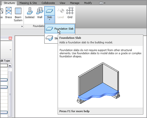
3. On the Foundation panel of the Structure tab, click Slab Foundation Slab, as shown in Figure 8.59.
4. In the Properties panel, click Edit Type.
5. Click Duplicate.
6. Call the new slab 12˝ Elevator Slab (300mm Elevator Slab).
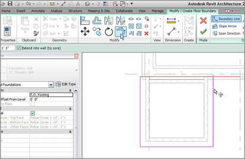
11. On the Draw panel, verify that the Pick Walls button is selected.
12. On the Options bar, set Offset to 1’–0” (300mm).
13. Pick the three elevator shaft walls, as shown by the numbers in Figure 8.61.
FIGURE 8.61 When picking the elevator shaft walls, be sure to include the 1´–0˝ (300mm) offset.
14. Set the offset back to 0.
15. Select the Pick Lines button. Verify that the offset is 0.
16. Pick the inside of the exterior foundation wall.
Now that the perimeter is set, it is time to start trimming the edges to make sure you have a continuous, closed loop:
1. On the Modify panel, click the Trim/Extend To Corner button.
2. Trim any overlapping corners, as shown in Figure 8.62.
3. On the Floor panel to the right of the Create Floor Boundary tab, click Finish Edit Mode.
4. Repeat the process for the south elevator.
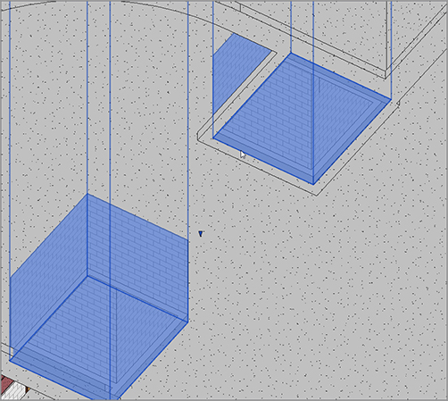
5. Go to a 3D view.
6. If your slabs look more like a strip footing, as shown in Figure 8.63, hover your cursor over the inside of one of the foundations until you see that you have the elevator shafts highlighted.
7. After the elevator shafts are highlighted, select it.
8. In the Properties dialog box, change the Base Offset to 0.
Now that the footings are mostly in place, it is time to think about placing piers and spread footings in the foundation. Luckily, as you are soon to discover, you already know how to do this.
Piers and Spread Footings
Piers and pilasters, simply put, are concrete columns. This is how Revit sees these items, and the following is the easiest placement method. A nice thing about this method is that the grids are in place as well as the steel columns that bear upon them. The only real trick is deciding which plan to put them in.
The objective of the next procedure is to add footings to the bottoms of the structural walls:
1. Return to the T.O. Footing plan.
2. On the Structure panel of the Structure tab, click the Column Structural Column button.
3. On the Insert tab, click the Load Family button, shown at the top of Figure 8.65.
4. Browse to Structural Columns Concrete.
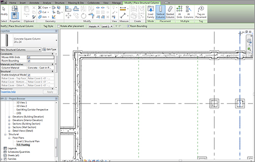
5. Pick the file called Concrete-Square-Column.rfa (M_Concrete-Square-Column.rfa).
6. Click Open.
7. In the Type Selector, select the 24 × 24 (600 × 600mm) column. Verify that the height is set to Level 1.
8. Start placing the columns at the grid intersections, as shown in Figure 8.65. Using At Grids can speed up your work.
Having a foundation in place in an architectural plan can be good and bad. It can be bad because structural items will start showing up in places you may not want to see them. The last procedure of the chapter involves isolating the structure from the architecture.
By creating a structural view, you are essentially duplicating an architectural view and hiding the structural items in that view. Sound easy? That’s because it is! Just follow these steps:
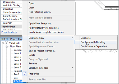
1. In the Project Browser, right-click T.O. Footing and select Duplicate View Duplicate With Detailing, as shown in Figure 8.68. The new view opens.
2. Rename the view called Copy of T.O. Footing to T.O. Footing Structural Plan.
FIGURE 8.68 Selecting Duplicate View Duplicate With Detailing
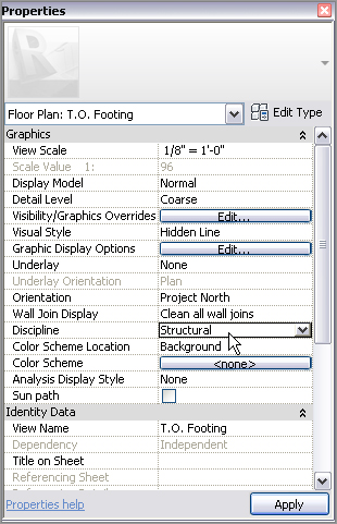
3. In the Discipline category of the View Properties, select Structural from the list, as shown in Figure 8.69. The sections disappear.
Now the Project Browser is broken down into categories. This will be helpful for large projects with a mix of structure and architecture.
This is getting easy! Now, let’s go make the Level 1 Architectural plan truly architectural:
1. Open the Level 1 Floor plan (Architectural).
2. Scroll down to View Range.
3. Click the Edit button in the View Range row.
4. Change both Bottom and View Depth offsets to 0.
5. Click OK.
The foundation information is no longer displayed in the Level 1 floor plan.
Although the last part of this chapter was short, it is a nice look into the Project Browser and shows how you can start to get organized. If you would like more practice, go into the Project Browser on your own and start organizing it the way you think you would like.