9: Ceilings and Interiors


CHAPTER 9
Ceilings and Interiors


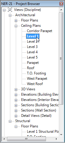
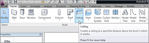
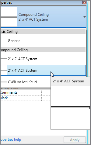
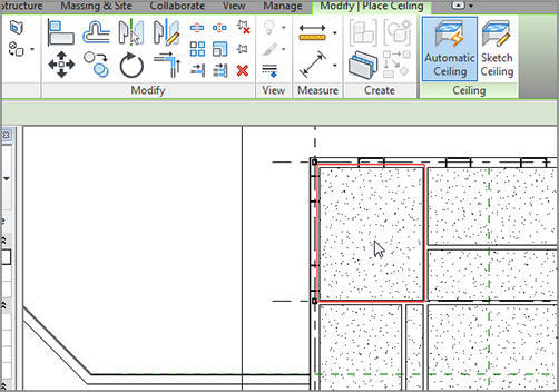
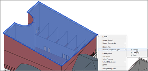
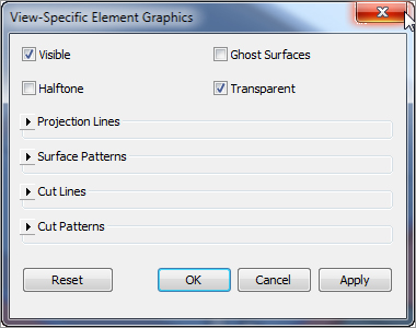
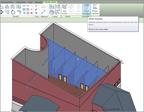
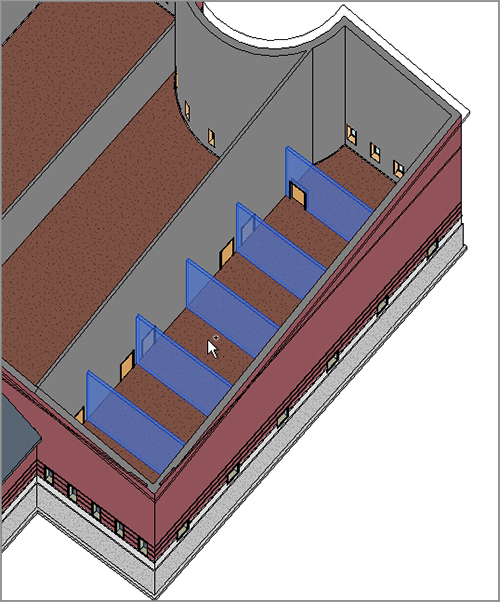
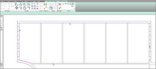
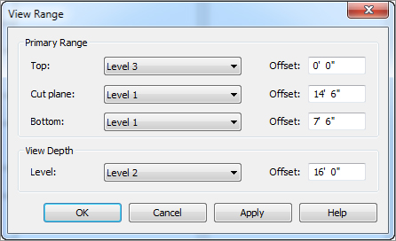
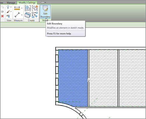
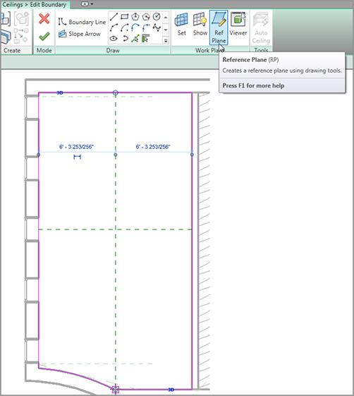
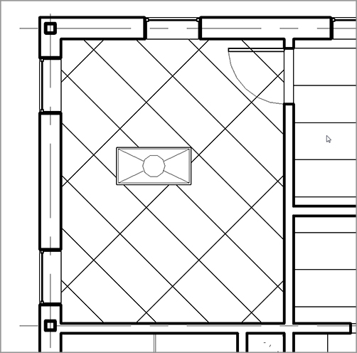
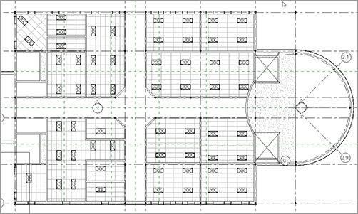
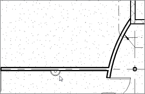
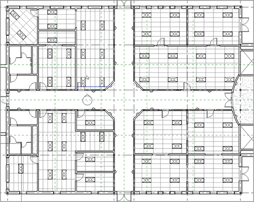
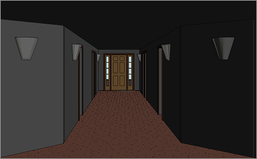
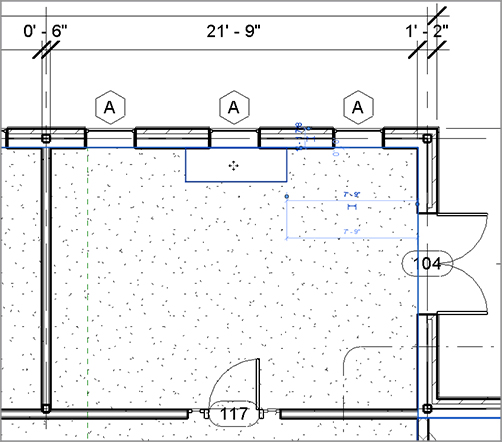
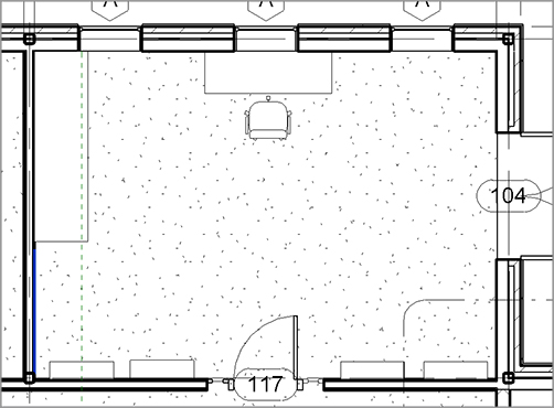
Now that the exterior shell is up and the rooms are basically laid out, it is time to start considering the interiors. As it stands, you have a bunch of rooms with the same wall finish, the same floor finish, and no ceilings to speak of. The restrooms don’t have any fixtures, and the rooms are going to be useless without furniture.


Another issue is that you don’t have any separate views such as furniture plans or finish plans. This chapter dives into all of these items—and then some!


  • Creating ceilings
  • Creating ceiling openings and soffits
  • Adding Interior Design
  • Adding alternate floor materials

Creating Ceilings


Placing a ceiling is quite easy; the hard part is finding the view in which to do it. As you have probably noticed, the Project Browser is divided into categories. The categories for plans are Floor Plans and Ceiling Plans. Whereas floor plans show the views standing at that level looking down, ceiling plans show the view standing at that level looking up. In Revit, you are looking at a true reflected ceiling plan.


To begin, open the file you have been following along with. If you did not complete Chapter 8, “Structural Items,” go to the book’s web page at www.sybex.com/go/revit2012ner. From there you can browse to Chapter 9 and find the file called NER-20.rvt.


  1. 1. Go to the Level 1 ceiling plan, as shown in Figure 9.1 (remember, this is a ceiling plan, not a floor plan).
    f0901.tif

    FIGURE 9.1 The Ceiling Plan category


  2. 2. On the Home tab, click the Ceiling button, as shown in Figure 9.2.
  3. 3. With the Ceiling command active, select Type Selector.
  4. 4. Choose 2´ × 4´ ACT System (600 × 1200mm Grid) from the Type Selector, as shown in Figure 9.3.
    f0902.tif

    FIGURE 9.2 The Ceiling button on the Home tab of the Design bar

    f0903.tif

    FIGURE 9.3 The available ceiling types listed in the Type Selector


  5. 5. Hover your mouse over the room shown in Figure 9.4. Notice that the perimeter is outlined in red. This indicates that the ceiling has found at least four walls you can use as a layout.
  6. 6. When you see the red outline, pick a point in the middle of the room. Your ceiling should now look like Figure 9.5.
  7. 7. Have at it! Add a ceiling to every room in the east wing except for the hallway, the bathrooms, East Radial Entry, and, of course, the elevator shafts, as shown in Figure 9.6.
  8. 8. With the Ceiling command still running, select Compound Ceiling : GWB On Mtl. Stud from the Type Selector.
    f0904.tif

    FIGURE 9.4 The ceiling finds a home.

    f0905.tif

    FIGURE 9.5 Placing the 2×4 tiled ceiling


  9. 9. Pick the bathrooms (not the chases) and the hallway.
  10. 10. Press Esc.

That was just too easy! Too good to be true, right? All right, it is. You always have to make adjustments to this type of item. You probably noticed that you had no control over which direction the grids were running. Also, you have no clue how high these ceilings are. It is time to start modifying the ceilings.

f0906.tif

FIGURE 9.6 Adding 2×4 ACT ceilings to the specified rooms


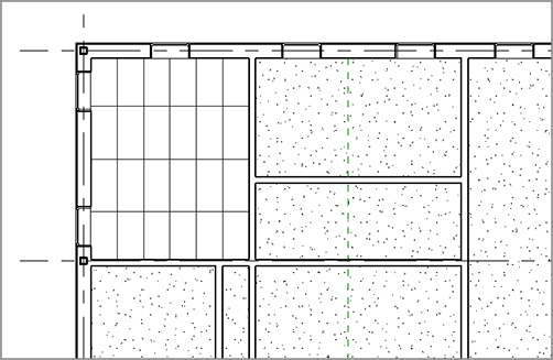
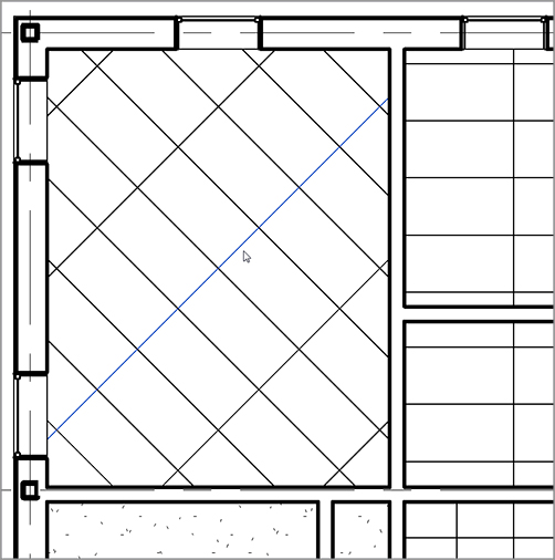
Modifying Ceiling Grids


To be honest, a ceiling consists of nothing more than a basic hatch pattern applied to a material. Actually, everything in Revit is a basic hatch pattern applied to a material. That sure does make it easy to understand!


The one unique thing about hatch patterns in Revit is that you can modify them onscreen. That means you can move and rotate a hatch pattern. That also means you can move and rotate a grid pattern. Let’s give it a shot:


  1. 1. Press Esc or Modify to cancel the command you may be in.
  2. 2. Pick the ceiling grid line, as shown in Figure 9.7. (Make sure you’re zoomed in close enough to make the Rotate command active.)
  3. 3. On the Modify | Ceilings tab, click the Rotate button, as shown in Figure 9.7.
  4. 4. Rotate the grid 45 degrees by using the two-pick method, as shown in Figure 9.8.

Your ceiling should now look like Figure 9.9.


Now that the ceilings are in, let’s look at the ceiling’s properties before you go too far. As a matter of fact, it is a good idea to investigate the ceiling’s properties before you place it in the model.


Setting Ceiling Element Properties


As I mentioned earlier, ceilings are set up in a similar fashion as floors. So, it stands to reason you will see many similar properties.


Before you get started, let’s make some modifications to the west wing. The objective of this procedure is to add a hard ceiling with metal framing, gypsum, and a 3/4˝ (18mm) cherry finish. To do so, however, you need to modify some of the walls:


  1. 1. Go to a 3D view of the model.
  2. 2. Select the sloped roof that covers the west wing, as shown in Figure 9.10.
  3. 3. Right-click.
  4. 4. Select Override Graphics In View images By Element (see Figure 9.10).
  5. 5. In the View-Specific Element Graphics dialog box, click the Transparent button in the upper-right corner, as shown in Figure 9.11.
  6. 6. Click OK. The roof is now transparent.
f0907.tif

FIGURE 9.7 Select one of the grids and click the Rotate button.

f0908.eps

FIGURE 9.8 The Rotate process

f0909.tif

FIGURE 9.9 The ceiling at a 45-degree angle

f0910.tif

FIGURE 9.10 Selecting the roof, and right-clicking

f0911.tif

FIGURE 9.11 The View-Specific Element Graphics dialog box


You made the roof transparent because some of the walls have to be attached to the roof. It is much easier to attach the walls in a 3D view. But to do so, you need to see the walls that you will be working on:


  1. 1. Select the wall shown in Figure 9.12.
  2. 2. On the Modify | Walls tab, select the Attach Top/Base button.
  3. 3. Pick the roof.

Your wall should look like Figure 9.12.

f0912.tif

FIGURE 9.12 Attaching the wall to the roof


The next step is to constrain the partition walls in this area to Level 3. The ceilings you will add to these rooms will be much higher than the rest of the building. Follow these steps:


  1. 1. While still in a 3D view, select the partitions shown in Figure 9.13.
    f0913.tif

    FIGURE 9.13 Selecting the partitions


  2. 2. In the Properties dialog box, set the Top constraint to Up To Level: Level 3.
  3. 3. The walls are now constrained to Level 3.
  4. 4. Select the roof that is transparent, right-click, select Override Graphics In View, click the Reset button, and then click OK.
  5. 5. Go to Level 1 under Ceiling Plans.

The next procedure is a tad off the beaten path but it fits squarely within this process. Because you have specified the walls in this area to be of a greater height than the rest of the walls in the model, you are obviously adding ceilings higher than 8´–0˝ (2400mm). This poses a problem in terms of the Level 1 ceiling plan view range.


Creating a Plan Region


Sometimes you will need to set your view range in a specific area that differs from the view range in the plan as a whole. In this example, you will add a ceiling at 14´–6˝ (4350mm) above the finish floor. If you do this with the current View Range settings, Revit will not display the ceiling. If you modify the View Range for the entire view, you will see the 14´–6˝ (4350mm) ceilings, but you will not see the regular 8´–0˝ (2400mm) ceilings in the rest of the building, in that view.


In the following procedure, you will create a region that has a different view range as compared to the view range in the Level 1 ceiling plan:


  1. 1. In the Project Browser, make sure you are in the Level 1 Ceiling Plan.
  2. 2. Zoom in to the west wing.
  3. 3. On the View tab, select the Plan Views images Plan Region button, as shown in Figure 9.14.
    f0914.tif

    FIGURE 9.14 The Plan Region button on the Create panel of the View tab


  4. 4. On the Draw panel, click the Pick Lines button, as shown at the top of Figure 9.15.
  5. 5. Pick the inside, finished face of the exterior walls around the north portion of the west wing, as shown in Figure 9.15.
  6. 6. For the lower-left corner, draw a straight line, as shown in Figure 9.15. (Unfortunately you can’t have radial perimeter lines in a plan region.)
f0915.tif

FIGURE 9.15 Defining the limits of the plan region by drawing a rectangle around a specific area


Notice that the View tab has now switched to the Modify | Create Plan Region Boundary tab. You need to define the view range for this region:


  1. 1. In the Properties dialog box, click the Edit button in the View Range row.
  2. 2. In the View Range dialog box, set the Top setting to Level 3.
  3. 3. Set Cut Plane Offset to 14´–6˝ (4350mm).
  4. 4. Set Bottom Offset to 7´–6˝ (2250mm).
  5. 5. Set View Depth Level to Level 2 with an Offset value of 16´–0˝ (4800mm), as shown in Figure 9.16.
    f0916.tif

    FIGURE 9.16 Configuring the View Range for the crop region


  6. 6. Click OK.
  7. 7. On the Mode panel, click Finish Edit Mode.

You now have a plan region. Although it may not seem as though you did anything in the plan, when you place a ceiling at 14´–6˝ (4350mm), you will be able to see it.


With the plan region in place, you can now place a ceiling at a higher distance from the finish floor. Because you are going to the trouble of placing a high ceiling, you might as well make the ceiling something special.


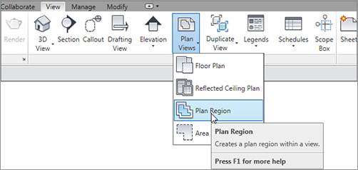
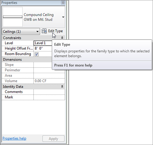
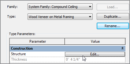
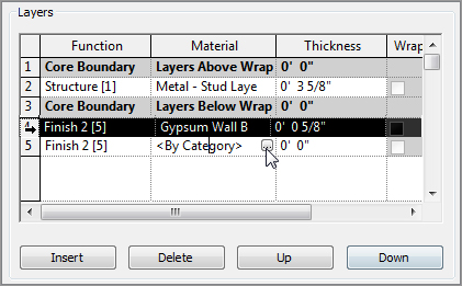
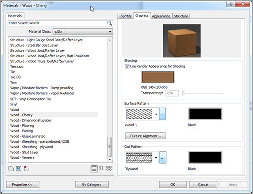
Creating a Custom Ceiling


So, what do you do if your ceiling is not an acoustical tile ceiling or a gypsum system? This is Revit! You make a new one.


As mentioned earlier, creating a ceiling is similar to creating a floor or a roof. The Properties dialog boxes are exactly the same. This procedure guides you through the process of creating a custom ceiling:


  1. 1. Be sure you are in the Level 1 ceiling plan, and zoom in on the northwest room.
  2. 2. On the Home tab, click the Ceiling button.
  3. 3. In the Type Selector, select GWB On Mtl. Stud. To the right and below the picture of the ceiling is the Edit Type button. Click it (see Figure 9.17).
  4. 4. Click Duplicate.
  5. 5. Name the new ceiling Wood Veneer on Metal framing and then click OK.
  6. 6. In the Structure row, click the Edit button, as shown in Figure 9.18.
  7. 7. In the Layers field, as shown in Figure 9.19, click on row 4. This is the Finish 2 [5] Gypsum Wall Board row.
    f0917.tif

    FIGURE 9.17 Clicking the Edit Type button after choosing the GWB On Mtl. Stud ceiling type

    f0918.tif

    FIGURE 9.18 Clicking the Edit button in the Structure row to gain access to the ceiling’s structural composition


  8. 8. Just below the Layers field is the Insert button. Click it.
  9. 9. Click the Down button to move the new row to the bottom.
  10. 10. Change the function from Structure to Finish 2 [5].
  11. 11. Click in the Material cell and click the […] button, as shown in Figure 9.19.
  12. 12. In the Materials dialog box, find Wood – Cherry.
  13. 13. To the right of the Materials dialog box, click the Graphics tab, as shown in Figure 9.20.
  14. 14. For Shading, click the Use Render Appearance For Shading check box.
  15. 15. Give it a Surface Pattern setting of Wood 1.
  16. 16. Give it a Cut Pattern setting of Plywood.
  17. 17. Click OK.
  18. 18. Change the Layer 5 thickness to 3/4˝ (18mm).
    f0919.tif

    FIGURE 9.19 Clicking the […] button in the Material cell

    f0920.tif

    FIGURE 9.20 Selecting and configuring the material for the ceiling


  19. 19. Click OK twice.
  20. 20. In the Properties dialog box, change the Height Offset from Level to 14´–6˝ (4350mm).
  21. 21. Place the ceiling in the room shown in Figure 9.21.
f0921.tif

FIGURE 9.21 The cherry-veneered plywood ceiling


For the adjacent rooms, add the same ceiling. You can keep the same height. You can follow along with these steps, but I encourage you to try to put the ceilings in from memory:


  1. 1. In the Project Browser, be sure you are in the Level 1 ceiling plan.
  2. 2. On the Home tab, click the Ceiling button.
  3. 3. In the Change Element Type menu on the Element panel, find the ceiling called Compound Ceiling : Wood Veneer on Metal framing (it will probably be the current selection).
  4. 4. In the Properties panel, set the height above the floor to 14´–6˝ (4350mm).
  5. 5. Pick the rooms shown in Figure 9.22. When you are finished, press Esc a couple of times or click Modify to clear the command.
f0922.tif

FIGURE 9.22 The north row of rooms will receive cherry ceilings!


Now that you have experience placing ceilings and creating custom ceiling systems, it is time to start adding features. The first items that come to mind are lighting fixtures, but you need to go back even further and figure out how to “cut holes” in the ceilings and add soffits.


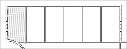
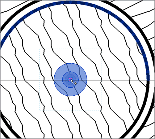
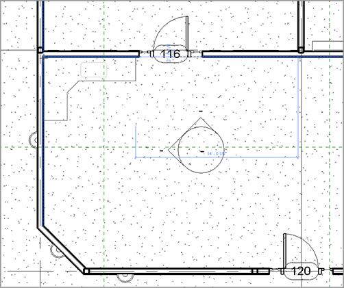
Creating Ceiling Openings and Soffits


Unless you are in a residential dwelling, or a prison, you can look up and notice that a ceiling is merely serving as a host for electrical, mechanical, and architectural components. Very seldom will you find a ceiling that does not require a modification in some capacity. This section of the chapter deals with this issue, starting with creating a ceiling opening.


Creating a Ceiling Opening
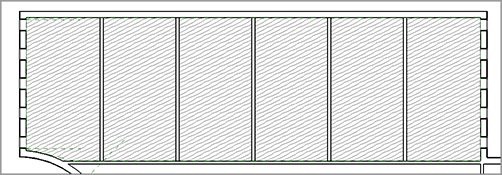
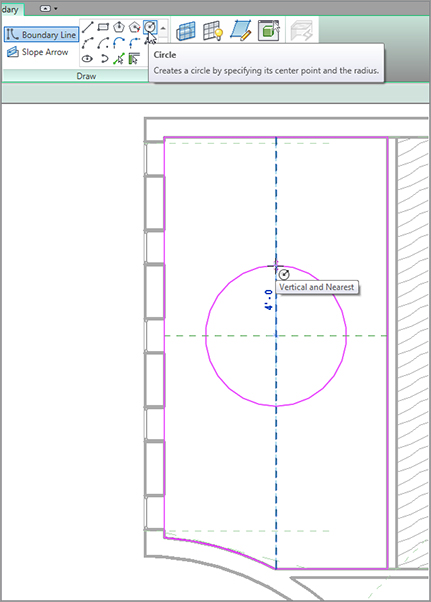
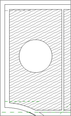
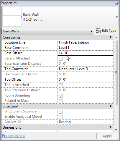
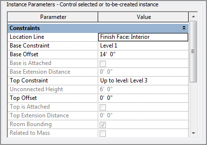
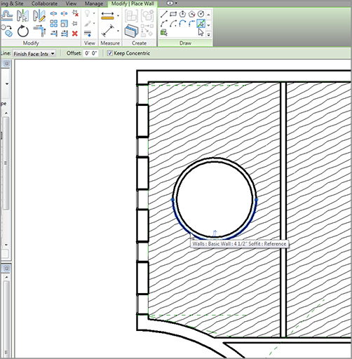

The objective of the next procedure is to cut an opening into a ceiling to later drop a soffit into:


  1. 1. Open the Level 1 ceiling plan.
  2. 2. Zoom in to the wood ceilings in the west wing, as shown in Figure 9.23.
  3. 3. Select the ceiling in the northwest corner of the building.
  4. 4. After the ceiling is selected, click the Edit Boundary button on the Modify | Ceilings tab, as shown in Figure 9.23. The ceiling pattern disappears and is replaced by a magenta sketch line at the perimeter of the room.
  5. 5. Click the Ref Plane button on the Work Plane panel, as shown in Figure 9.24.
  6. 6. Draw two reference planes, as shown in Figure 9.24. Be sure to snap to the midpoints of the magenta sketch lines.
  7. 7. With the reference planes drawn, hit Esc a couple of times or click Modify to clear the Ref Plane command.
  8. 8. On the Draw panel, click the Boundary Line button. You will see an expanded list of sketch choices. Pick the Circle choice, as shown in Figure 9.25.
    f0923.tif

    FIGURE 9.23 Clicking the Edit Boundary button on the Modify | Ceilings tab


  9. 9. Draw a 4´–0˝ (1200mm) radius circle at the intersection of the reference planes (see Figure 9.25).
  10. 10. On the Mode panel, click Finish Edit Mode.
  11. 11. Verify that your ceiling looks like Figure 9.26.

With the cutout in place, you need to think about closing this feature with a soffit and, perhaps, another ceiling.


Creating a Soffit


Soffits are nothing more than walls with a base offset. This makes sense if you think about it. If your floor level moves, you certainly want the distance from the finish floor to the bottom of the soffit to remain consistent. This one is going to be easy!


  1. 1. On the Home tab, click the Wall button.
  2. 2. In the Type Selector, select Basic Wall : Interior: 6 1/8˝ Partition (2 Hr).
  3. 3. Click the Edit Type button.
  4. 4. Click Duplicate.
  5. 5. Call the new wall 4 1/2˝ Soffit. (Metric users, call it 112mm Soffit.)
  6. 6. Click OK.
  7. 7. Click the Edit button in the Structure row.
  8. 8. Delete rows 1 and 7 (the double gypsum layer).
  9. 9. Change the gypsum thicknesses for rows 1 and 5 to 1/2˝ (112mm).
  10. 10. Change the Stud layer to 3 1/2˝ (90mm).
  11. 11. Click OK twice (see Figure 9.27).
    f0924.tif

    FIGURE 9.24 Drawing two reference planes to create a center intersection

    f0925.tif

    FIGURE 9.25 Sketching a 4´–0˝ (1200mm) radius circle

    f0926.tif

    FIGURE 9.26 There’s a hole in my ceiling!

    f0927.tif

    FIGURE 9.27 Modifying the dimensions of the 6 1/8˝ wall


  12. 12. In the Properties dialog box, set Base Offset to 14´–0˝ (4200mm), as shown in Figure 9.28.
  13. 13. Set Top Constraint to Up To Level: Level 3 (see Figure 9.28).
f0928.tif

FIGURE 9.28 Setting the Top Constraint and Bottom Offset


You are now ready to place the soffit. You will add it to the radial hole in the ceiling. Normally, you would need to physically draw the wall by using the Arc Sketch function. In this case, you can simply pick the radial portion of the ceiling opening:


  1. 1. With the Wall command still running, click the Pick Lines icon on the Draw panel.
  2. 2. Mouse over the radial ceiling opening. Notice that a blue alignment line appears. Make sure it is to the inside of the opening and then press the Tab key twice.
  3. 3. Notice that the entire circle is selected and the blue alignment line is facing the inside of the hole (see Figure 9.29). When you see this, pick a point to the inside of the hole.
    f0929.tif

    FIGURE 9.29 Creating one cool soffit!


  4. 4. Press Esc twice or click Modify.

Your soffit is complete.


It is now time to add a secondary ceiling to the inside of the soffit. This procedure is carried out exactly as it was when you added a ceiling to the entire room:


  1. 1. In the Project Browser, go to the Level 1 ceiling plan and zoom in on the ceiling with the soffit.
  2. 2. On the Home tab, click the Ceiling button.
  3. 3. Select Compound Ceiling : Wood Veneer On Metal Framing (if it is not the current selection already).
  4. 4. Click the Edit Type button.
  5. 5. Click Duplicate.
  6. 6. Call the new ceiling Mahogany Veneer on Metal Framing and then click OK.
  7. 7. Click the Edit button in the Structure row.
  8. 8. Click in the bottom layer, and click the […] button to change the material, as shown in Figure 9.30.
    f0930.tif

    FIGURE 9.30 Click the […] button to change the material.


  9. 9. In the Materials dialog box, find Wood – Cherry
  10. 10. Click the Duplicate button, as shown in Figure 9.31.
  11. 11. Call the new material Wood – Mahogany.
  12. 12. Click the Appearance tab.
  13. 13. Find the Wood category, as shown in Figure 9.32.
  14. 14. Choose Mahogany – Stained Dark Polished, as shown in Figure 9.32.
  15. 15. Go to the Graphics tab.
  16. 16. Change Surface Pattern to Wood 2.
  17. 17. Click OK twice.
  18. 18. Click OK one more time to get back to the model.
    f0931.tif

    FIGURE 9.31 Duplicating a material

    f0932.tif

    FIGURE 9.32 Making mahogany


  19. 19. In the Properties dialog box, change Height Offset From Level to 14´–1˝ (4225mm).
  20. 20. Place the ceiling inside the soffit. Click Modify.

You need to adjust your plan region; it has to be set so the cut plane is either below or equal to 14´–1˝ (4225mm) so you can see the lower ceiling:


  1. 1. Pick the dotted rectangle surrounding the rooms. This is the plan region.
  2. 2. On the Modify | Plan Region tab, click the View Range button.
  3. 3. Change the Offset value for the cut plane to 14´–1˝ (4225mm).
  4. 4. Click OK.

Your ceiling plan should look like Figure 9.33.

f0933.tif

FIGURE 9.33 The completed ceiling


You are getting there with this ceiling, that’s for sure! The only task left is to add some light fixtures.


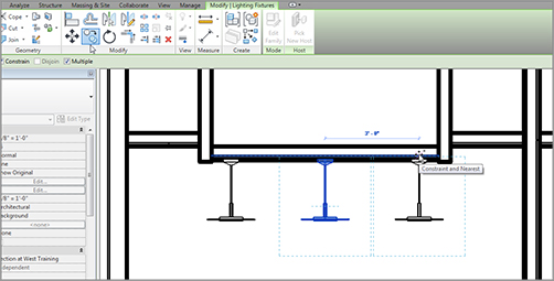
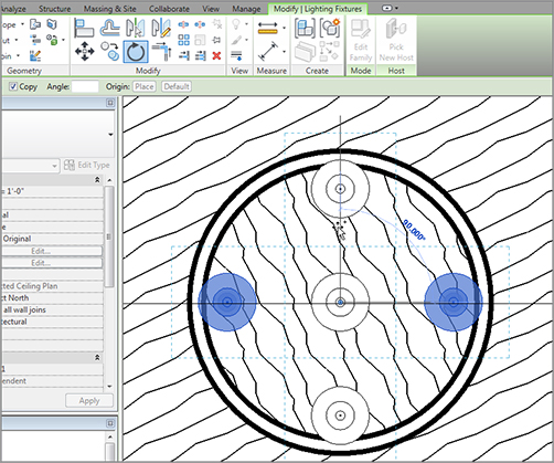
Adding Light Fixtures to Ceilings


Adding lighting fixtures to a Revit Architecture model is not a difficult task, but you must follow a few guidelines to achieve success in installing lighting. For example, you must work with the Ribbon to find a face in which to insert the component:


  1. 1. Go to the Level 1 ceiling plan, where you have been adding the wood ceilings.
  2. 2. On the Home tab, click Component images Place A Component, as shown in Figure 9.34.
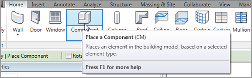
    f0934.tif

    FIGURE 9.34 Click Place A Component on the Home tab


  3. 3. In the Mode panel of Modify | Place Component, click Load Family, and then browse to Imperial Library images Lighting Fixtures (Metric Library images Lighting Fixtures).
  4. 4. Open the file Pendant Light – Disk.rfa (M_Pendant Light – Disk.rfa).
  5. 5. Place the light approximately as shown in Figure 9.35. Click Modify.
    f0935.tif

    FIGURE 9.35 Moving the fixture to the correct location


  6. 6. Move the light to the center of the radial soffit. This time, you can use snaps (see Figure 9.35).
  7. 7. Open the section called West Training. Notice that the light fixture is in the exact location you expected it to be.
  8. 8. Select the fixture.
  9. 9. Click the Copy button on the Modify Lighting Fixtures tab, as shown in Figure 9.36.
    f0936.tif

    FIGURE 9.36 Copying the fixtures in the section


  10. 10. On the Options bar, be sure the Multiple button is selected.
  11. 11. Copy the fixture 3´–0˝ (900mm) to the right and 3´–0˝ (900mm) to the left (see Figure 9.36).

The main point of having you open a section to copy the fixtures is to illustrate that you are now in a fully modeling environment. When you switch back to the plan, you will see that the fixtures have been moved. In later chapters, you will learn that this will also add line items to schedules.


Now, let’s make some more fixtures:


  1. 1. In the Project Browser, go to the Level 1 ceiling plan.
  2. 2. Zoom in on the radial soffit. You will see the two new fixtures.
  3. 3. Select the right and left fixtures.
  4. 4. Click the Rotate command on the Modify | Lighting Fixtures tab.
  5. 5. On the Options bar, make sure Copy is selected.
  6. 6. Rotate the fixtures 90 degrees to create a total of five fixtures, as shown in Figure 9.37.

Now that you have experience dealing with ceilings, it is time to start working on some interior design. Ceilings are a part of this, but what about wall treatments, trims, and architectural millwork? These items will be covered in the next section.

f0937.tif

FIGURE 9.37 You are now copying and rotating as if you were in flat, 2D AutoCAD.


Adding Interior Design


Congratulations! You have arrived at possibly the most difficult subject when it comes to 3D modeling. Why is that? Well, for starters, this is the area where nothing is easy in terms of shape, configuration, and for some projects, the sheer amount of millwork and detail. For example, suppose you want a crown molding at the ceiling where it intersects the walls. And suppose you need the same crown at the radial soffit. Of course, the floors and walls are not the same material, and you need to add furniture as well.


I can go on and on listing the complications you will face here, so let’s just jump in. The first part of the process is adding plumbing fixtures and furniture.


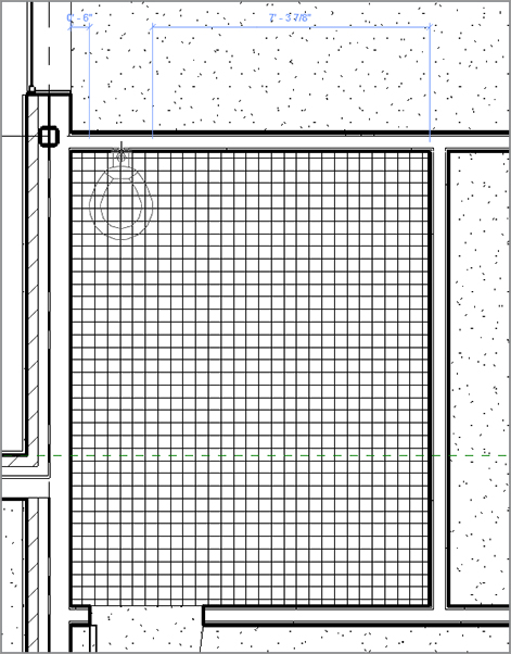
Adding Plumbing Fixtures and Furniture


Adding a desk follows the same procedure as adding a light fixture. Notice, though, that when you added the light fixture, it just “knew” that it was supposed to be hosted by the ceiling. It is important to note that most furniture is not hosted by a floor; it is actually hosted by a level. This becomes very important if you have a floor system offset from a level. Your furniture will ignore the floor and stick to the level it is associated with.


To begin, you will have to knock off the less glamorous but all-too-important task of adding bathroom fixtures:


  1. 1. In the Project Browser, go to the Level 1 floor plan (floor plan, not ceiling plan).
  2. 2. Zoom in on the lavatory area, and turn off the thin lines mode, as shown in Figure 9.38.
  3. 3. As you can see, there is a callout of this area. Double-click the callout bubble to open the view called Typical Men’s Lavatory.
    f0938.tif

    FIGURE 9.38 The lavatory area


  4. 4. With the Typical Men’s Lavatory view opened, you can start adding some fixtures. In the Insert tab, click the Load Family button.
  5. 5. In the Imperial Library (or Metric) directory, browse to the Plumbing Fixtures folder.
  6. 6. Select the file called Toilet-Commercial-Wall-3D.rfa (M_Toilet-Commercial-Wall-3D.rfa) and click Open.
  7. 7. Go to the Home tab and click the Component button.
  8. 8. If you see a dialog box asking whether you want to load a plumbing fixture tag, click No.
  9. 9. In the Type Selector, make sure the 19˝ Seat Height (480mm Seat Height) toilet is selected.
  10. 10. Place it along the north wall approximately 6˝(150mm) from the west wall, as shown in Figure 9.39.

Because you’re not creating a military barracks from the 1960s, you need some stalls. Unfortunately, Revit does not provide any stalls out of the box, but this book you bought does! To add some toilet stalls to the model, go to the book’s web page at www.sybex.com/go/revit2012ner. From there, you can browse to Chapter 9 and find these files:


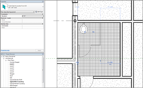
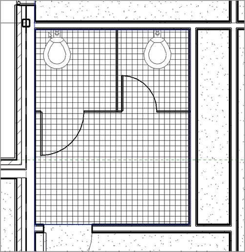
  • Toilet Stall-Accessible-Front-3D.rfa
  • Toilet Stall-Accessible-Side-3D.rfa
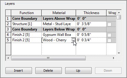
  • Toilet Stall-Braced-3D.rfa
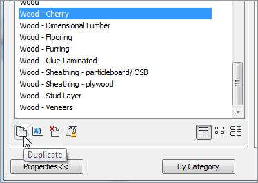
  • Grab Bar.rfa
  • Double Sink – Round.rfa
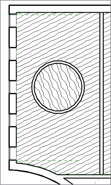
After you locate the files, download them to the location where you keep all of your Revit families. Then follow along with the procedure:


  1. 1. On the Insert tab, click Load Family.
  2. 2. Browse to the location where the new families are kept and select the new files; then click Open. They are now loaded into your project.
  3. 3. On the Home tab, click the Place A Component button.
  4. 4. Select Toilet-Stall-Accessible-Front-3D 60˝ × 60˝ Clear.
  5. 5. Pick the corner of the bathroom, as shown in Figure 9.40.
f0939.tif

FIGURE 9.39 Placing the 19˝ (480mm) Seat Height toilet 6˝ (150mm) from the west wall, along the north wall

f0940.tif

FIGURE 9.40 Placing the accessible stall


The next step is to copy the toilet and add another stall. It would be nice if the family just fit, but this is not a perfect world!


  1. 1. Copy the toilet to the right 6´–2 1/2˝ (1862mm).
  2. 2. On the Home tab, select the Place A Component button.
  3. 3. Select Toilet Stall – Braced – 3D 59˝ × 60˝ Clear.
  4. 4. Click Edit Type.
  5. 5. Click Duplicate.
  6. 6. Name the new stall type 54˝ ×60˝ Clear (1350 × 1500mm Clear). Set the width to 4´–6˝ (1350mm).
  7. 7. Place the stall in the model (see Figure 9.41).
f0941.tif

FIGURE 9.41 The two toilets and stalls in place


With the toilets and the stalls in place, you need to add a grab bar to the accessible stall. Again, Revit does not provide this content. You need to either make this component yourself (this is covered in Chapter 17, “Creating Families”) or use the one from the book that you downloaded with the bathroom stalls.


To add a grab bar, follow these steps:


  1. 1. Zoom in on the accessible stall, as shown in Figure 9.42.
  2. 2. Click the Place A Component button.
  3. 3. Select Grab Bar 4´–0˝ (1200mm) Length.
  4. 4. Place the grab bar along the wall, as shown in Figure 9.42.
f0942.tif

FIGURE 9.42 Adding the grab bar family to the wall


Because you are in the men’s room, it is time to add some urinals. You can fit two before you start getting too close to the sink area, and the guy standing next to you:


  1. 1. On the Insert tab, click the Load Family button.
  2. 2. Browse to Plumbing Fixtures.
  3. 3. Select the file called Urinal-Wall-3D.rfa (M_Urinal-Wall-3D.rfa).
  4. 4. Click Open.
  5. 5. Click the Component button, and place two urinals about 6˝ (150mm) away from the front of the stall, with a 1´–0˝ (300mm) space between the two, as shown in Figure 9.43.
f0943.tif

FIGURE 9.43 Adding the urinals to the men’s room


What a relief to get those urinals in! The next step is to get a sink with two stations installed into the bathroom. To do this, you can use the double sink you loaded from the book’s website:


  1. 1. On the Home tab, click the Place A Component button if it is not still running.
  2. 2. In the Change Element Type menu, find the family called Double Sink – Round 24˝ Depth (Double Sink – Round 600mm Depth).
  3. 3. Place it into the corner, as shown in Figure 9.44.

Because the women’s room is the same size, there will be two stalls and a sink. Create the mirrored layout shown in Figure 9.45.


Now that the first-floor bathrooms are done, let’s move over to some of the actual rooms and offices to furnish these rooms. The first thing you need to do is to add lighting to the ceilings.


Adding Parabolic Troffers


As you are starting to see, the procedure for adding a component does not change based on the component you are adding. This is great news. Adding a troffer, however, is slightly different. You do need to be in a ceiling plan, and you do need to specify the face of the ceiling.

f0944.tif

FIGURE 9.44 Placing the double sink


At this point, you may be good enough at adding these fixtures to simply look at the following figures and add the lights yourself. Or, if you desire a little help, follow these steps:


  1. 1. In the Project Browser, go to the Level 1 ceiling plan. (Notice that you are going to a ceiling plan right now, not a floor plan.)
  2. 2. Zoom in on the northwest corner of the east wing, as shown in Figure 9.46.
  3. 3. On the Insert tab, click the Load Family button.
  4. 4. Browse to the Lighting Fixtures folder.
  5. 5. Select the file called Troffer Light – 2×4 Parabolic.rfa (M_Troffer Light Parabolic Rectangular.rfa).
  6. 6. Click Open.
    f0945.tif

    FIGURE 9.45 Completing the women’s room


  7. 7. Click the Place A Component button; then place the fixture in your ceiling, as shown in Figure 9.46.
  8. 8. Click the Align button on the Modify tab, as shown in Figure 9.47.
  9. 9. Align the light fixture to the grid.
  10. 10. Copy the light to the location shown in Figure 9.48.
  11. 11. Add lights to the rest of the rooms in the east wing, as shown in Figure 9.48. It will be quickest to place a single light horizontally and one vertically, align them to the grids, and then make multiple copies.
  12. 12. In the Properties dialog box, click the View Range button.
  13. 13. Set the cut plane to 4´–0˝ (1200mm).
f0946.tif

FIGURE 9.46 Placing a light in a ceiling. You will be aligning it to the grid in a moment.


With the lights added to the suspended ceilings, you need to illuminate the corridors. This can be done by adding a set of wall-mounted sconces, as follows:


  1. 1. Select the Level 1 floor plan.
  2. 2. On the Insert tab, click Load Family.
  3. 3. Browse to the Lighting Fixtures folder.
  4. 4. Select the file called Sconce Light – Uplight.rfa. (M_Sconce Light – Uplight.rfa).
  5. 5. Add the sconce to the corridor wall, as shown in Figure 9.49.
    f0947.eps

    FIGURE 9.47 Aligning the fixture to the grid

    f0948.tif

    FIGURE 9.48 Adding lights to the rest of the ceilings

    f0949.tif

    FIGURE 9.49 Adding a sconce


  6. 6. Add sconces to the walls of the hallways as appropriate, as shown in Figure 9.50.
    f0950.tif

    FIGURE 9.50 Copying the sconce to the other hallway walls


  7. 7. In the Project Browser, double-click on the 3D view called East Wing Corridor Perspective. This gives you a good idea of how the up-lighting influences the corridor (see Figure 9.51).
f0951.tif

FIGURE 9.51 Looking at the hallway in a perspective view


Well, that corridor is looking great! It’s time now to start looking into the offices, and also to see whether you can get a kitchen area completed.


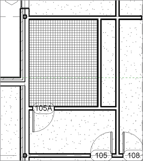
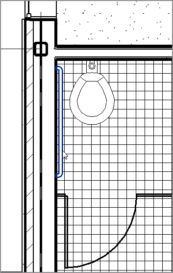
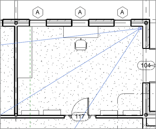
Adding Casework and Furniture


Adding casework and furniture is the easiest part of this chapter—that is, if you like the casework and furniture that comes right out of the Revit box. Something tells me that this is not going to be adequate. For this chapter, you will be using the out-of-the box items, but in Chapter 17, you will make some custom millwork families.


To add some office furniture, follow along:


  1. 1. Select the Level 1 floor plan.
  2. 2. Zoom in to the northeast corner office, as shown in Figure 9.52.
  3. 3. On the Insert tab, click the Load Family button.
  4. 4. Browse to the Furniture folder and select the following five items:

    • Cabinet-File 5 Drawer.rfa (M_Cabinet-File 5 Drawer.rfa)
    • Chair-Executive.rfa (M_Chair-Executive.rfa)
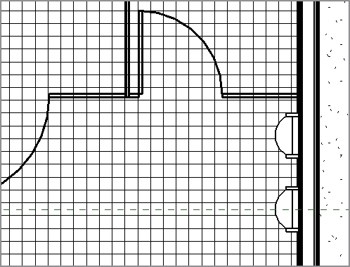
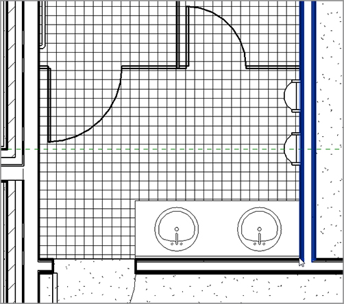
    • Credenza.rfa (M_Credenza.rfa)
    • Entertainment Center.rfa (M_Entertainment Center.rfa)
    • Shelving.rfa (M_Shelving.rfa)

  5. 5. Click the Place A Component button; then, in the Type Selector, select Credenza 72˝ × 24˝ (1830 × 610mm).
  6. 6. Place the credenza desk into the room, as shown near the top of Figure 9.52.
  7. 7. On the Home tab, click the Place A Component button if the command isn’t still running.
  8. 8. From the Type Selector, select Chair-Executive and place it in front of the credenza, as shown in Figure 9.53.
    f0952.tif

    FIGURE 9.52 Placing the credenza desk into the first office


  9. 9. In the Type Selector, select the Entertainment Center 96˝ × 84˝ × 30˝ (2743 × 2134 × 762mm) and place it in the corner, as shown in Figure 9.53.
  10. 10. Place four 36˝ (915 × 0254 × 1830mm) shelving units across the south wall, as shown near the bottom of Figure 9.53.
f0953.tif

FIGURE 9.53 Adding furniture to the office


At this point, it is a good idea to take a perspective shot of this office to see if this space is developing the way you were envisioning. Although you may never put this perspective view onto a construction document, it is still a great idea to see what is going on:


  1. 1. On the View tab, select the 3D View images Camera button.
  2. 2. Pick a point in the northeast corner.
  3. 3. Pick a second point beyond the southwest corner, as shown in Figure 9.54. The new view opens. You will probably want to stretch the crop boundaries.
  4. 4. In the Project Browser, right-click on the new 3D view and call it Perspective of Corner Office.
    f0954.tif

    FIGURE 9.54 Adding a camera (perspective view) to the corner office


  5. 5. You can change the Visual Style setting to Shaded, and even turn on shadows, if you need to do so. Remember, however, shadows are unnecessary and will slow down the view dramatically (see Figure 9.55).

It’s time for a kitchen! This is such a nice office that there seems to be a need for a break area right outside. You would not want your esteemed executive to have to walk very far for a cup of coffee or a snack.


To get started, you’ll load some countertops and cabinets:


  1. 1. On the Insert tab, click the Load Family button.
  2. 2. Browse to the Casework folder.
  3. 3. Open the Domestic Kitchen folder.
  4. 4. Select the following families:

    • Base Cabinet-2 Bin.rfa
    • Base Cabinet-Double Door & 2 Drawer.rfa
    • Base Cabinet-Double Door Sink Unit.rfa
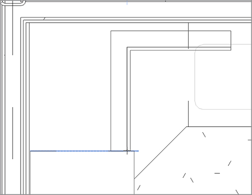
    • Base Cabinet-Filler.rfa
    • Base Cabinet-Single Door & Drawer.rfa
    • Counter Top-L Shaped w Sink Hole 2.rfa
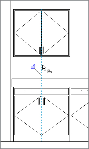
    • Upper Cabinet-Double Door-Wall.rfa
      f0955.tif

      FIGURE 9.55 The perspective of the corner office. If you notice that your entertainment unit is backward, you will have to go back to the plan to rotate it.


  5. 5. Click Open.
  6. 6. Also, load the file called 
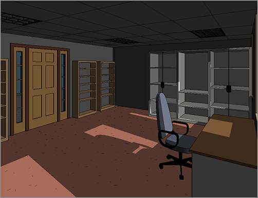
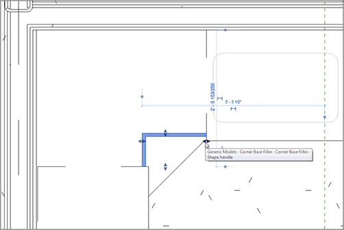
Corner Base Filler.rfa from the book’s website within the Chapter 9 directory.
  7. 7. Open Floor Plan Level 1. Zoom in on the kitchen area, as shown in Figure 9.56.
  8. 8. Add the countertop, as shown in Figure 9.56.
  9. 9. Press Esc twice.
  10. 10. Select the countertop.
  11. 11. Select the stretch arrows and stretch the leg of the counter to the end of the wall, as shown in Figure 9.57.
    f0956.tif

    FIGURE 9.56 Adding the countertop


  12. 12. Add the Base Cabinet-Double Door Sink Unit 30˝ (900mm) under the sink.
  13. 13. Align the base unit under the sink.

You now have a counter and a sink base. The problem is, you have no idea how high these items are or what they really look like. That’s okay—this is Revit. You just need to create two elevations for these items, as follows:


  1. 1. On the Create panel on the View tab, click the Elevation button.
  2. 2. Add an interior elevation looking north, as shown in Figure 9.58.
  3. 3. Select the elevation marker and turn on the elevation looking west (see Figure 9.58).
    f0957.tif

    FIGURE 9.57 Lengthening the counter leg to meet the corner of the wall


  4. 4. Rename the north elevation to Kitchen North.
  5. 5. Rename the west elevation to Kitchen West.

With the elevations in, you can now flip back and forth to make sure you are putting the items in the right places, and to get a good idea of how your cabinet run is looking.


The remainder of the procedure involves adding the rest of the cabinets. Let’s do it!


  1. 1. On the Home tab, click the Place A Component button.
  2. 2. From the Type Selector, select Base Cabinet – Single Door & Drawer 24˝ (600mm).
  3. 3. Place the base cabinet to the right of the sink cabinet.
  4. 4. Press Esc twice or click Modify; then open the Kitchen North elevation. Does your elevation look like Figure 9.59?
    f0958.tif

    FIGURE 9.58 Adding elevations to aid in design

    f0959.tif

    FIGURE 9.59 The elevation of the cabinet run


  5. 5. Go back to the Level 1 floor plan.
  6. 6. Place a Base Cabinet Double Door & 2 Drawer 36˝ (900mm) in the position shown in Figure 9.60.
    f0960.tif

    FIGURE 9.60 Placing the 36˝ (900mm) double-door, two-drawer base cabinet


  7. 7. Press Esc twice or click Modify; then select the Kitchen West elevation.
  8. 8. Move the base cabinet so there is a 1˝ (25mm) counter overhang, as shown in Figure 9.61.
  9. 9. Copy the base cabinet to the right three times (four total cabinets), as shown in Figure 9.62.
    f0961.tif

    FIGURE 9.61 The 1˝ (25mm) overhang on the end

    f0962.tif

    FIGURE 9.62 The base cabinet run


  10. 10. Go back to Level 1 and click the Place A Component button.
  11. 11. Find Corner Base Filler.
  12. 12. Place it into the model on the side of the base cabinet, as shown in Figure 9.63.
  13. 13. Select the filler.
  14. 14. Stretch the grips until the filler resembles Figure 9.64.
f0963.tif

FIGURE 9.63 Adding the filler

f0964.tif

FIGURE 9.64 The completed corner


The bases are done! It is time to add some wall cabinets to the kitchen. I think at this point you will have enough experience to go on your own to populate the rest of your building as you see fit.


  1. 1. On the Home tab, click the Place A Component button.
  2. 2. In the Type Selector, select Upper Cabinet-Double-Door-Wall 36˝ (900mm).
  3. 3. Place the wall cabinet in the model, as shown in Figure 9.65. (Don’t worry too much about aligning it to the cabinet below. You will align it in elevation.)
    f0965.tif

    FIGURE 9.65 Adding the wall cabinet


  4. 4. Open the Kitchen West elevation.
  5. 5. Click the Align button on the Modify tab.
  6. 6. Align the wall cabinet to the base cabinet, as shown in Figure 9.66.
    f0966.tif

    FIGURE 9.66 Aligning the wall to the base


  7. 7. Copy the wall cabinet to the right three times (for four total cabinets).
  8. 8. Save the model.

Your cabinets should look like Figure 9.67.


Now that the kitchen is in place, it would be nice to add a tile floor only to that area. You can accomplish this without having to add extra floors to the model. You can simply split the face of the floor that is already there, and add an additional material.


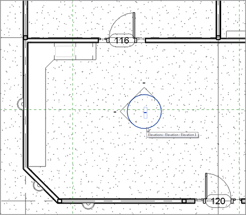
Adding Alternate Floor Materials


Carpeting does not perform well in kitchens. This is information you already know. What you don’t know is how to add tile to a carpeted floor system without having to cut the existing floor and start piecing in sections of alternate materials. That’s what you’ll learn in this section.

f0967.tif

FIGURE 9.67 The finished west wall of the kitchen


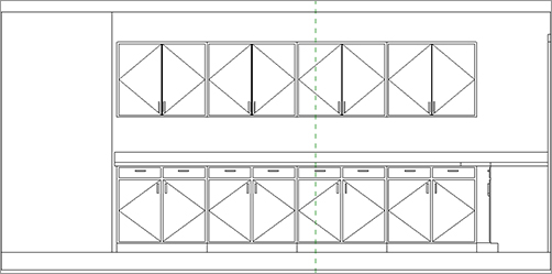
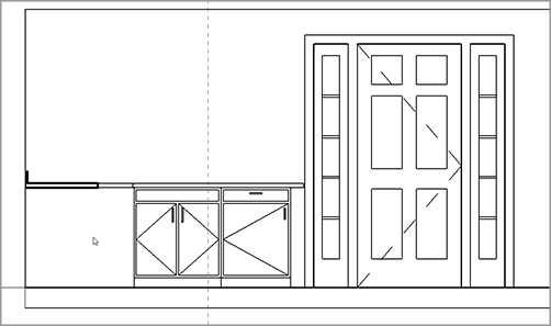
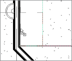
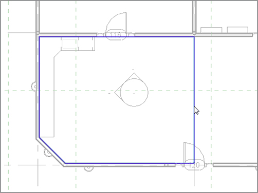
Separating the Floor


Now that we have a floor area targeted for a new material, the following procedure guides you through the steps:


  1. 1. Open the Level 1 floor plan. Click the Split Face button on the Modify tab, as shown near the top right of Figure 9.68.
  2. 2. Select the entire floor. This may require finding the edge of the floor along an exterior wall (see Figure 9.68).
  3. 3. Click the Line button on the Draw panel. Draw a continuous line around the kitchen, as shown in Figure 9.69.
  4. 4. On the Modify | Split Face images Create Boundary tab, click Finish Edit Mode.

Although it does not seem like it, you have split the kitchen from the rest of the floor. Next you’ll apply a material to the kitchen. The first step will be to create a suitable material to use.

f0968.tif

FIGURE 9.68 Clicking the Split Face button and selecting the slab edge

f0969.tif

FIGURE 9.69 Drawing the perimeter of the alternate floor material


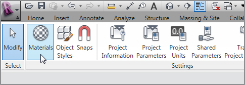
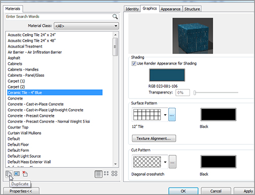
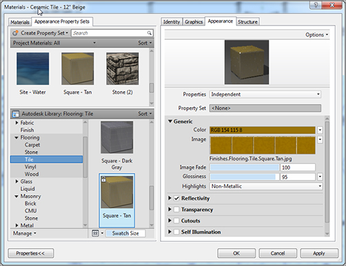
Creating a Tile Material


There is one tile material in this model, but it would be beneficial to create a new one with 12˝ (300mm) square tiles. This procedure takes the place of using hatching in a conventional drafting situation.


Follow this procedure to create a new material:


  1. 1. On the Manage tab, click the Materials button, as shown in Figure 9.70.
  2. 2. In the Materials dialog box, scroll down and select Ceramic Tile – 4˝ (100mm) Blue.
    f0970.tif

    FIGURE 9.70 Choosing the Materials button on the Manage tab


  3. 3. At the bottom-left of the dialog box, click the Duplicate button, as shown in Figure 9.71.
  4. 4. Call the new material Clay Tile – 12˝ Beige (Clay Tile – 300mm Beige).
  5. 5. Go to the Graphics tab.
  6. 6. Change Surface Pattern to 12˝ (300mm) Tile (see Figure 9.71).
  7. 7. Select the Use Render Appearance For Shading check box.
  8. 8. Click the Appearance tab.
  9. 9. Under Flooring, go to Tile and then select Square – Tan, as shown in Figure 9.72. Click OK.

The new material is locked, loaded, and ready to spill onto the floor! To do this, you will paint to apply the new material to the kitchen. Follow along:


  1. 1. Click the Paint icon in the Geometry panel of the Modify tab, as shown in Figure 9.73.
  2. 2. Select Clay Tile – 12˝ Beige from the Material Class drop-down list, as shown in Figure 9.74.
  3. 3. Put your paint icon over the edge of the kitchen floor until the region becomes highlighted.
  4. 4. When the region becomes highlighted, pick the floor. Your new tile appears. Click OK in the Materials dialog box.
f0971.tif

FIGURE 9.71 Creating a new tile


Phew! You are gaining a good amount of experience in terms of adding components and making the interior of the building conform to your design. If you think about it, you have done nothing here that is out of the ordinary. You are simply replacing everyday drafting routines with modeling routines. What a way to go!

f0972.tif

FIGURE 9.72 Mapping out the rendering and the shading appearance

f0973.tif

FIGURE 9.73 The Paint button


Because there is quite a bit of building left, go ahead and load this model up with components. If you get stuck anywhere, go back and find the procedure that pertains to your problem.

f0974.tif

FIGURE 9.74 Selecting Clay Tile


Are You Experienced?


Now you can…


  • add ceilings to a room as well as create new ceilings and modify them to suit your needs
  • transfer ceilings from other projects by using the Transfer Project Standards function
  • add soffits to your model by using a typical wall and offsetting the base
  • create a plan region so you can see elements at different elevations without disturbing the rest of the view
  • add components such as bathroom fixtures, office furniture, and lighting to your model
  • create subregions in which to specify an alternate flooring, thus allowing you to avoid hatching

Aug 3, 2021 | Posted by in Building and Construction | Comments Off on 9: Ceilings and Interiors
Premium Wordpress Themes by UFO Themes