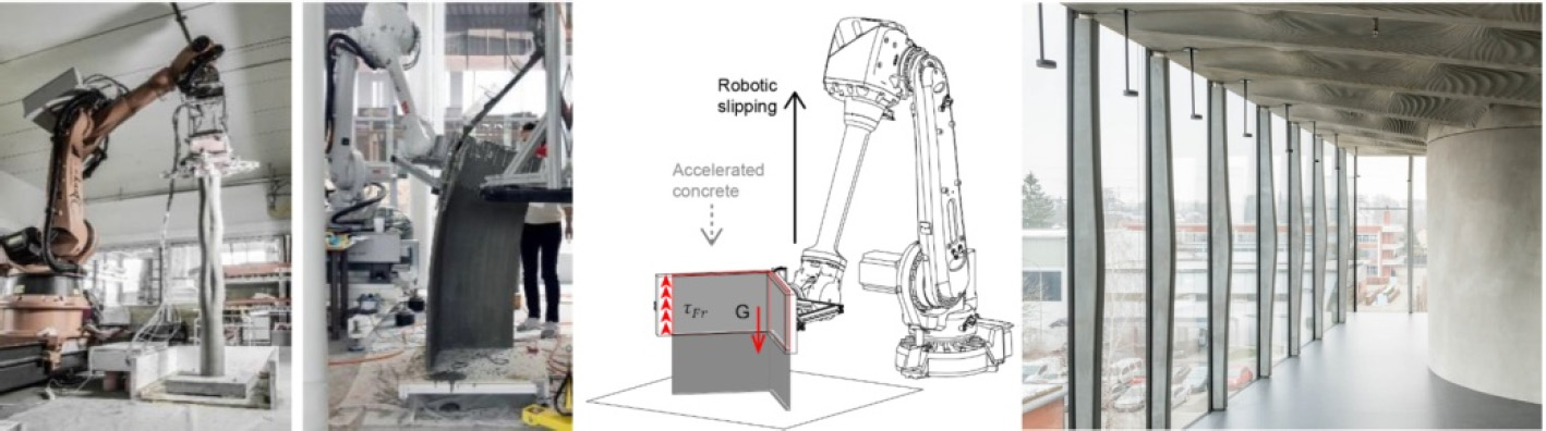
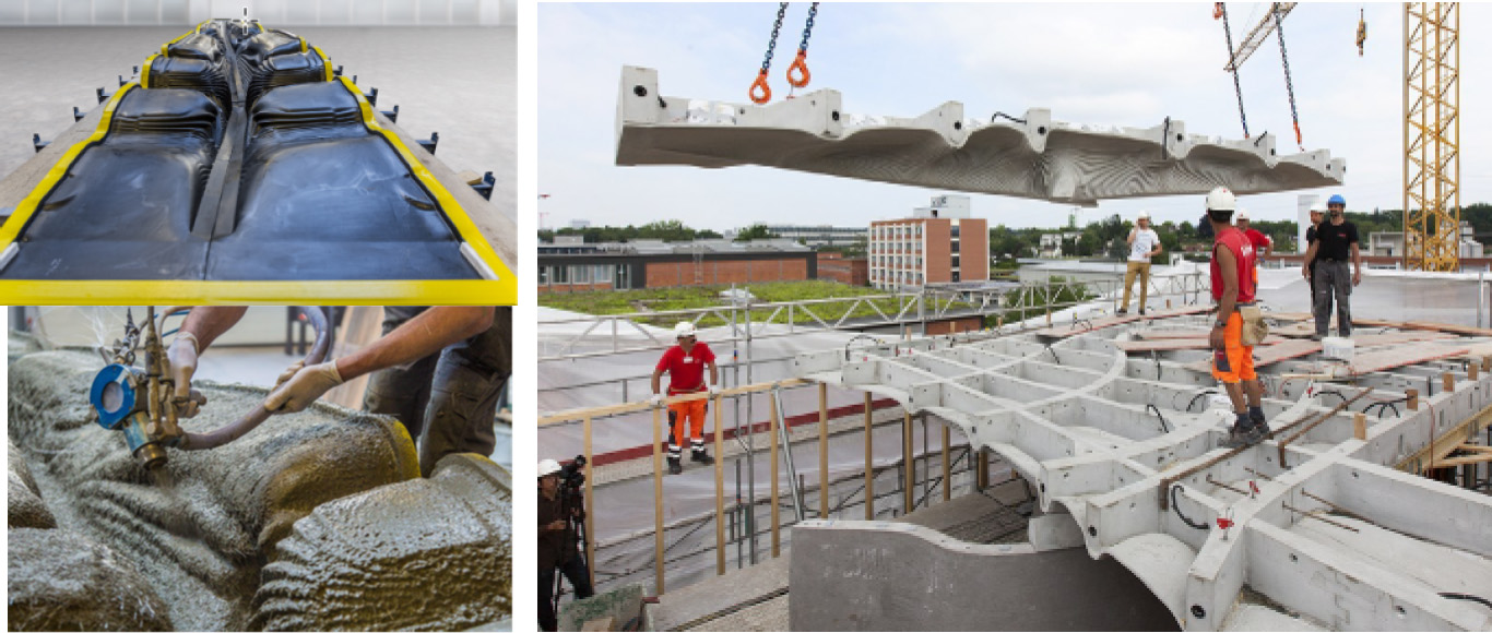
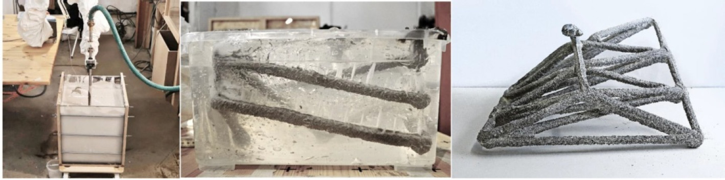
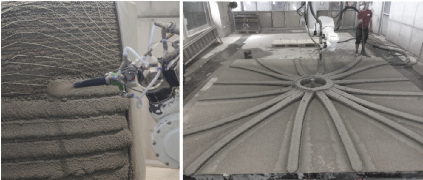
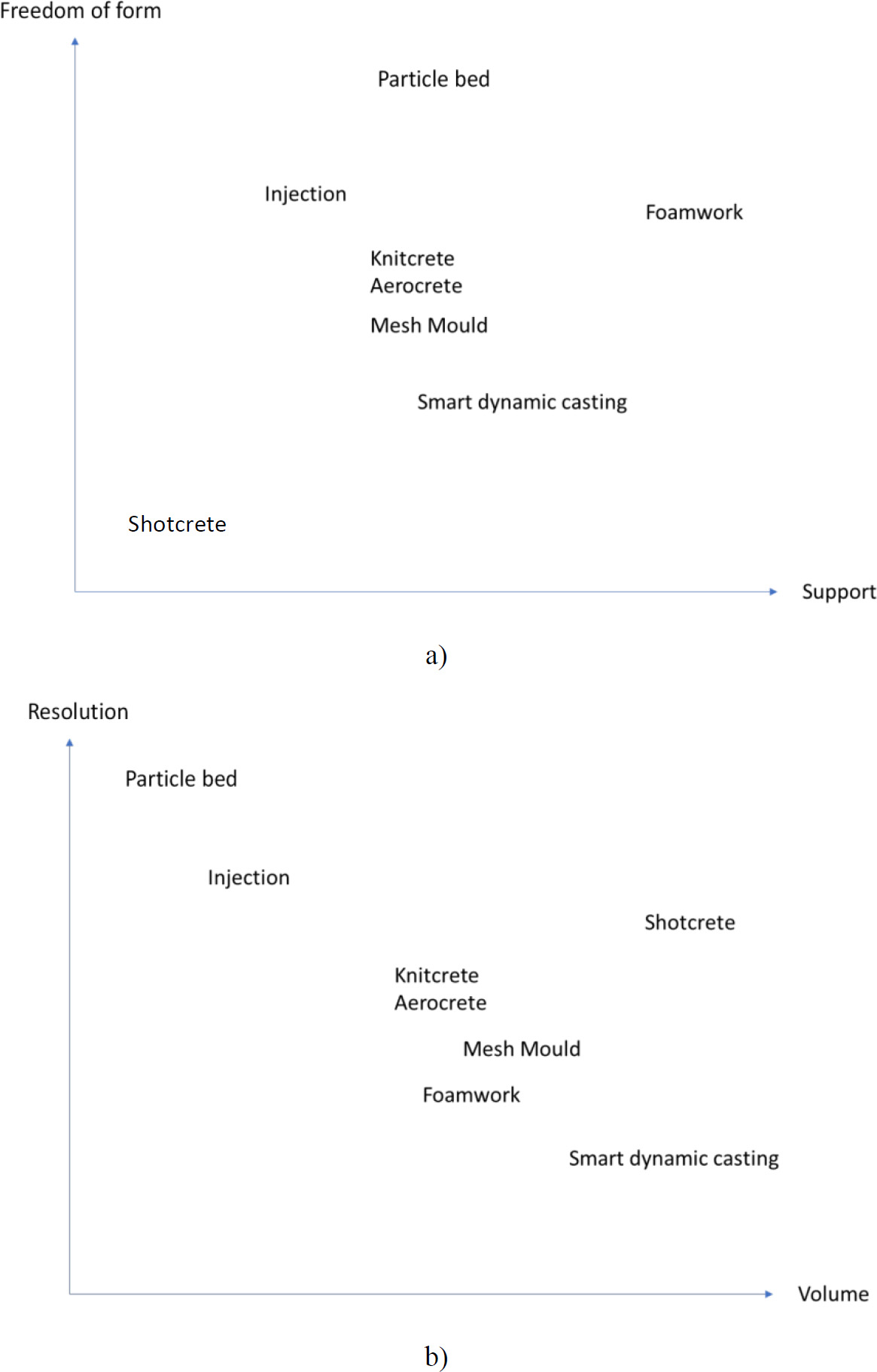
Alexandre PIERRE1 and Arnaud PERROT2 1 CY Cergy Paris Université, France 2 IRDL, Université de Bretagne Sud, Lorient, France Robotic concrete construction goes beyond the technique of depositing successive layers or filaments, which then solidify. In the field of construction materials, 3D printing technologies are multiple and not limited to extrusion 3D printing. Spatial resolution and absolute freedom of form can be achieved by alternative 3D printing techniques, which we will discuss in this chapter. Large-scale 3D printing projects for new housing, structures (like pedestrian bridges) or smaller scale equipment and street furniture are currently being carried out using 3D extrusion printing. Their number is currently growing, and they require R&D before they can be marketed. In terms of the number of construction sites, the main applications of 3D printing are limited to relatively simple shapes with little variation in cross-section, and optimized material quantities that are not always financially or environmentally profitable. Indeed, a relatively thin filament thickness is required to achieve an environmental gain (Kuzmenko et al. 2022). The cost of customized formwork, stable productivity since the 1950s and the unusual use of robotics also limit a massive breakthrough of this process on the construction market. As early as 2016, some authors were already raising questions about the mass use of 3D printing in civil engineering (Wu et al. 2016). Bearing in mind that concrete construction elements are legally subject to compliance with Eurocodes standards, the freedom of design and complexity of form brought about by digitalization are reduced. Printed concrete elements are generally used as lost formwork, or as temporary (or even permanent) supports made from other materials. This opens up a wide range of possibilities, including the alternative techniques described in this chapter. The desire to create elements assembled in the form of structures from materials in their fresh state, driven by technical and environmental choices, has prompted some players in the field to extend their technologies beyond the traditional extrusion triptych: liquid shaping, deposition and solidification. The main difficulty not fully solved by extrusion 3D printing is to form the material without spatial constraints and to add structural reinforcements. There is a real need for innovation to meet the challenge of innovative, disruptive 3D printing in the construction sector. Alternative techniques for additive manufacturing of construction materials need to be explored. In this chapter, a number of alternative additive manufacturing processes will be presented. The impact of using alternative 3D printing methods could be immense: building components with customized properties and optimized shapes can reduce waste and improve the energy efficiency of buildings. The opportunity to actually have materialization in space with these techniques could be interesting for the construction sector. The freedom of form of a printed work or element, both for practical, functional and aesthetic reasons, is the main ambition of emerging 3D printing techniques. What are the current possibilities offered by alternative digital manufacturing techniques to break free from a process dominated solely by the superimposition of printed filaments? Do alternative techniques meet the main objectives of 3D printing, which are currently unattainable with the extrusion technique? These include reducing the amount of material used, minimizing waste and reusing materials, designing elements for circularity and reuse, manufacturing functional geometries through their freedom of form and increasing automation in prefabrication. Other possibilities are yet to be explored, both for housing renovation and refurbishment, and for urban design and structural ornamentation. In this chapter, the alternative 3D printing processes to extrusion will be explored, presenting the most well-documented and recent alternative techniques. The main aim of this summary chapter is to highlight the current strengths and limitations of alternative additive manufacturing techniques applied to cementitious materials. Printing concrete material alone is sometimes not enough to meet the functional (structural, thermal or aesthetic) requirements of the printed element. One way of ensuring that the material is held in place when it is placed by the robot is to use a support. This support initially acts as a holding device for the material, leaving the printer head. It can be solid, non-deformable or flexible, liquid, moving or fixed. It is also possible to use a so-called sacrificial support, which can be reused. Sacrificial supports are commonly used in polymer 3D printing, but remain confidential in the field of civil engineering. We can classify techniques using solid supports or sacrificial supports, in situ. On the one hand, the advantage of a solid support is that it can be re-used, but this contradicts the advantage of 3D printing’s freedom of form, particularly in the original sense of formwork, which is to repeat modules or elements in series. On the other hand, printed formwork that remains in place, or in situ formwork, is ideally suited to bringing functionality to the material to be poured into it. It must go beyond the mere aesthetic or geometric aspect that a conventional extrusion process can satisfy. It can provide structural support (reinforcement or textile fibers), acoustic and thermal comfort (foam), help against carbonation (polymer) or can improve durability on the surface exposed to external environmental stresses. Alternative 3D printing techniques aim to create more complex shapes than extrusion. However, the infinite possibilities of printed structures are still a long way off. One reason is that the material leaving the nozzle has relatively low mechanical strength compared with other printable materials such as metal alloys. From an architectural point of view, the manual placement of metal reinforcement as sacrificial formwork was, for example, a solution used for the Taichung Metropolitan Opera House (Figure 4.1). The introduction of robotized reinforcement placement has modernized the manufacture of this type of structure, with permeable formwork and the introduction of curved, slender geometries. Historically, this process, which ultimately involves printing a mesh or lattice permeable formwork, known as “mesh mould”, was first developed using polymers from 2013 onward (Boyd IV et al. 2020; Jipa and Dillenburger 2022). Figure 4.1 shows the device developed at ETH Zurich for printing the formwork into which the concrete will be poured (Hack and Lauer 2014; Jipa and Dillenburger 2022). It consists of a printhead capable of bending (front part), cutting and welding steel reinforcement bars (rear part). The scientific challenges of this technique are, on one scale, the same as those developed several years ago by flowing concrete through reinforcement cages (Vasilic et al. 2011, 2016). The present case is more complex, because instead of allowing concrete to pass through the reinforcement, the process requires the material to be partially blocked, then equivalent to a “liquid stone”. In fact, it is necessary to fill the space inside the formwork with reinforcement and cover it on the visible side of the element in order to preserve its service life. The characteristic size of the mesh and its permeability must match the characteristic size of the material in place. This type of element is suitable when external conditions are not extreme or do not have a high impact on the durability of the structure, due to the finer coverage of the reinforcement, rather than with traditional concrete. Figure 4.1. Left: interior and exterior architecture of the Taichung Metropolitan Opera House (© Fcuk1203 © An adaptation of the mesh mold technique was developed in 2018 using a fibrous mortar sprayed onto a permeable carbon fiber structure (Taha et al. 2019). This technique, known as “aerocrete”, enables curved and very fine shapes. The right compromise between the permeability of the formwork and the size of the fibers used is necessary to obtain adequate encapsulation of the structure. However, the quantities of material lost during spraying and the poor surface quality have, for the time being, kept this technique at the prototype stage (Szabo 2020). The disadvantages of this technique include the need to adapt the spraying process to the size and geometry of the mesh (speed, quantity, trajectory, flow rate, etc.). The curing time of the sprayed concrete is also an important parameter for potential industrialization of the process. The “Knitcrete” process, developed in 2016, uses a 3D printer to produce a textile structure using a technique similar to robotic knitting. The textile fibers are then assembled and tensioned. One side of the textile is sprayed with a quick-setting calcium aluminate cement, and concrete is then added to the other side (Popescu et al. 2018; Popescu 2019). The advantages of these structures are lightness and easy transport of the textile elements, while avoiding complex assemblies. Concrete curing times also need to be adapted for on-site or outdoor applications. The mechanical contribution of the textile structure remains to be assessed. Figure 4.2 shows elements obtained with these two techniques. Figure 4.2. Top left: model of robot trajectory; bottom left: textile structure sewn and fully covered; right: robotic spraying of building material onto textile structure (photographs from Rennen et al. 2023) Future work in 3D printing will increasingly incorporate the improvement of properties on the scale of building physics. To this end, mineral foams are cellular materials generally used for thermal insulation, thanks to their air cavities (the material’s main constituent). They are mainly used to limit heat loss in buildings. However, traditional methods require considerable manpower to apply this type of insulation on site. An alternative 3D printing technique is to use these binders as permanent or temporary formwork. Figure 4.3 illustrates a process involving the 3D printing of mineral foam modules, which are left in place to provide acoustic or thermal functionalities. It is also possible to remove these modules to make room for the structure’s cavities and lighten the structure. The state of the art by Bedarf et al. (2021) reviews the applications and processes used and highlights two advantages. The first is the lightness of the structure due to the air cavities and the second is environmental, with improved thermal performance and reduced use of materials. There are still a number of unresolved technological issues to be addressed, including material formulation, foaming control, printing techniques and on-site developments. Figure 4.3. Self-supporting mineral foam formwork system. a) 3D printing of mineral foam components; b) resulting mineral foam components; c) mineral foam elements attached to wooden formwork; d) mineral foam elements embedded in concrete (photos © Bedarf, P., Calvo-Barentin, C., Schulte, D.M., from Bedarf et al. (2023), licensed under CC BY 4.0) The main challenge is to stabilize the material’s properties and control the evolution of its porosity over time and during the process. When a foam is set in motion during processing, it undergoes forces, notably shear forces (Goyon et al. 2010). It must also resist compressive forces during installation, while remaining compressible. This antagonism requires a thorough understanding of the material’s behavior and properties. The nature of the binder, the size, morphology and distribution of the cavities are parameters to be controlled when using this technique (Bedarf et al. 2021). To this end, the porous structure is generally obtained by combining mechanical and chemical actions. During mixing, air is incorporated and the expansion of the mixture is linked to the amount of foaming agents added to the mix. As a reminder, the order of magnitude of the thermal conductivity of “traditional” concrete is 0.5 W·m–1K–1 for a density of 250 kg/m3, whereas “foamed” concrete can reach a density close to 250 kg/m3 with a thermal conductivity of 0.065 W·m–1·K–1. 3D extrusion printing sometimes generates defects at the interface of the printed layers, known as cold joints (Perrot et al. 2021). This difficulty in assembling and reuniting layers means that the structure will have a limited lifespan, depending on external stresses. What is more, in the event of late layer overlap, drying phenomena will create micro-structural defects, which can then degenerate the primary functionality of the printed element. A different approach, proposed back in 2012 by ETH Zurich and known as Smart Dynamic Casting, involves shaping concrete with a (sliding) formwork whose (dynamic) trajectory is robotized. The concrete enters the formwork in a liquid state and emerges from the formwork in a solid state in just a few minutes. The advantage of this technique lies in its quasi-continuous process. Compared with conventional extrusion, there are no defects at the interface. The material must be structured, hydrated and set to suit the trajectory of the dynamic formwork. As this trajectory is generally vertical, the correlation of the two speeds – material structuring and robot movement – is essential. Technologically, in the early work developed at ETH Zurich and explained in (Lloret-Fritschi et al. 2017, 2020), a flexible, controllable membrane was arranged at the mold outlet. This made it possible to obtain sections scaled to one-fifth the diameter of the mold. The main challenge during the process is to reduce friction when lifting the mold. In fact, this work has shown that the weight of the formwork decreases sharply during vertical movement, synonymous with the phenomenon of friction (Szabo et al. 2019b, 2020b). Lubricating systems at the interface are therefore essential for the success of these structures. Compared with conventional slipforming, the SDC technique opens up two possibilities: transforming the geometry and volume of the final form, thanks to the process (robot rotation, adjustable speed, etc.). The speed of the formwork must be adapted to the hydration rate of the concrete, so that it can support its own weight and that inside the formwork. Yield stress values for material flow can therefore be higher than those used in extrusion. The success of this process depends on the compromise between the force due to gravity and the frictional force generated along the mold during movement. Buckling of the structure is also a difficulty to be taken into account when designing the shape. A limitation to the use of an articulated arm, synonymous with freedom of form in the space allocated to the arm’s movement, is sometimes not possible because the weight of the formwork and material cannot be supported by the robot. This calls for the use of gantry systems, which reduce architectural freedom. The systems developed offer two options: either modify the cross-section of the material by adapting the movement or by placing devices at the nozzle outlet, or modify the formwork, automatically inducing a change in the shape of the material. The second, simpler option reduces stresses on the material, but can lead to significant frictional effects. Figure 4.4 illustrates the evolution of the dynamic slipform technique according to Lloret-Fritschi et al. (2020). Figure 4.4. Examples of the SDC technique. From left to right: slipforming with changes in cross-section during elevation of the printed column; thin structures, schematic representation of force balance during the process (photos from Szabo et al. 2020b, licensed under CC BY 4.0); beams produced using the SDC technique (photo from Lowke et al. 2024, licensed under CC BY 4.0) Flexible supports of various materials can also be filled with concrete deposited along a robotized trajectory. This process, also developed in Zurich as a continuation of the work on smart dynamic casting, is slightly different. The formwork, made of textile, paper or plastic, is tensioned but remains static, while the concrete is poured following the robot’s trajectory. A support structure for these flexible molds is installed beforehand to give the object its final shape. Developed in Szabo’s thesis work (Szabo 2020), the concrete must have an “over-demand” structure and set to reduce the pressure exerted on the formwork, which is too thin and of low rigidity to support the weight of the material. Figure 4.5 shows, for example, a flexible polyethylene (PE) support tensioned between two wooden supports. Filling speeds can be rapid of the order of 2.5 m/h (Lloret-Fritschi et al. 2020). We also note that the formwork device here is affordable and easy to set up. The difficulties lie in rheological and chemical control of the material poured into the flexible formwork, and in appropriate robot control. It is essential to formulate a rapidly hydrating material due to the low capacity of flexible supports to withstand hydrostatic pressure. To achieve this, aluminum sulfate must be added to the formulation. It promotes rapid ettringite formation and increases the material’s yield stress. We can see from Figure 4.5 that surface aspects are obviously correlated with the material used (smooth surface for PE, opaque for cardboard, slightly rough for geotextile). Figure 4.5. Robotic concrete casting in PE film under tension (photographs from Szabo et al. 2019a, licensed under CC BY 4.0) The recycling of plastic materials makes it possible to use extruded polymer as formwork. This temporary formwork until the concrete solidifies is then more easily printable with high resolution of the final part, thanks to hindsight on 3D printing of polymer-based material. This process is referred to as “eggshell”. The principle is simple: print the thinnest possible skin or layer at high resolution and place the concrete on it, either upstream or simultaneously with the concrete pour (Lloret-Fritschi et al. 2020). The challenge is to adapt the mold filling speed to the mechanical performance of the polymer formwork and the structural build-up of the concrete, due to its so-called thixotropy, in order to limit hydrostatic pressure. The process does not allow rapid production due to the relatively long time required to print the polymer. Similarly to each alternative technique with a solid support material, the placement of structural reinforcements is possible. Figure 4.6 shows several examples of parts produced using this technique, including a reinforced column 1 m 80 cm high. Figure 4.6. Illustration of projects using the polymer printing technique as formwork; left: simultaneous printing of polymer and pouring of cementitious material; middle and right: printed column with reinforcement and use as part of the “future tree” project; photos taken from Jipa and Dillenburger (2022) and Lowke et al. (2024) It is also possible to use substrates with a thickness of less than 1 mm, but a counterpressure system is required to ensure stability when the concrete is placed. In this case, the concrete used is not formulated to harden and hydrate very quickly, as the pressure is taken up by a sand bank placed around the printed mold. An example is shown in Figure 4.7. Here, several dozen elements were 3D printed with a biopolymer to make formworks (Jipa et al. 2019). These elements were then assembled by cold welding. Then, concrete, fluid enough not to clog the channels of the printed mold shapes, was injected. The sand, rising parallel to the level of the concrete, was placed within the structure, to relieve the stresses imposed on the mold. Finally, the biopolymer-printed elements are removed using a heat source. This technique of holding together two devices – the printed mold and a sand pressure-relief system – has proved its effectiveness in obtaining complex shapes, but there are currently no large-scale demonstrators in the construction sector. Interestingly, other materials can also be used as temporary supports, such as folded paper (Lloret-Fritschi et al. 2022) or printed raw earth (Bruce et al. 2022). Figure 4.7. Manufacturing a canoe by injecting cementitious material into printed biopolymer modules. Photos from Jipa and Dillenburger (2022) and Lloret-Fritschi et al. (2017) and the work of Jipa et al. (2019). Left: from top to bottom: printed parts before assembly; layout on sand; example of detail obtained. Right: printed canoe The binder jetting technique can be used to print on different types of materials (geopolymer, cement, etc.). This technique consists of producing a structure by jetting a liquid binder onto a powder matrix, layer after layer. Moulds are printed and then used as formwork to place concrete, sometimes reinforced with fibers. On a large scale, we can cite several works (Ranaudo et al. 2010; Jipa et al. 2016; Aghaei Meibodi et al. 2018; Anton et al. 2020), including the beam created within the DFab and the Swiss pavilion temporarily installed in Venice in 2016 according to the thesis of Popescu (2019). Both projects combine a mold printed with this technique with shotcrete (15–20 mm thick) and cast concrete (Jipa et al. 2023). Treatment of the printed form with polyester resins is sometimes necessary to obtain a smooth surface prior to the concrete shotcrete stage. Structures printed with these techniques are generally discretized into several parts. It is therefore necessary to plan the connections between each part (see Figure 4.8, right). The elements are then assembled by post-tensioning. Four further steps are required: mold preparation, filling by casting or spraying, concrete curing and demolding. We note that the hybrid solution of spraying concrete onto the mold to prevent cracking, then pouring the concrete to encapsulate the reinforcement, improves manufacturing time. This process makes it possible to obtain optimized shapes and reproduce details that are impossible to reproduce using conventional manufacturing techniques and extrusion printing. The addition of shotcrete to the mold also makes it possible to produce finer, functional and aesthetic structures that would be impossible to achieve by pouring concrete. The main advantage and paradigm of 3D printing can be fulfilled by reducing the quantity of materials used. For example, the “smart slab” beam has made it possible to reduce the weight of the concrete used by 40% compared with a prestressed lightweight concrete beam (Jipa et al. 2023). However, this process is still time consuming, particularly during the design/discretization of the elements and the manufacturing/assembly stage. As an example, the beam shown in Figure 4.8 required 181 printed parts, 114 polymer printed connectors and 2,140 plywood panels. It is also necessary to master several complementary techniques, digital or otherwise, for assembly (3D plastic printing, laser cutting, milling, etc.). Figure 4.8. Left: 3D printed mold; spraying concrete onto the mold. Right: assembling the structure; photographs taken from Jipa et al. (2023) In their fresh state, cementitious materials are subject to Newton’s first law, and all the problems encountered during extrusion stem from the force of gravity. In order to counteract gravity and provide support for the concrete as it is deposited, it is possible to immerse the robot’s needle or nozzle in a carrier fluid and place the cementitious material in it (Benamara et al. 2020). The injection technique therefore involves extruding a fluid cementitious material into another fluid material with specific rheological properties. Archimedes’ principle is not sufficient to hold the cementitious material. The carrier fluid acts as a temporary support until the element solidifies if it has yield stress fluid behavior. As a reminder, this type of fluid behaves like a solid below a certain shear stress and like a fluid above it. Once the cementitious material has been placed, the carrier fluid must therefore have a high yield stress to counteract the drag force of the deposited material. It must also be thixotropic so that it returns to its initial state as quickly as possible after passing through the nozzle. More widely used in the medical field for the production of cells (Murphy and Atala 2014; Eshkalak et al. 2020), this strategy guarantees precision and efficiency with regard to the risk of the structure collapsing during printing. Injection and then the stability of the printed form also depend on rheological and physicochemical compatibility. It is necessary to avoid the formation of co-products through any interaction between the injected material and the carrier liquid. The recent study by Lowke et al. (2021) provides an overview of some of the physics underlying these issues. Figure 4.9 shows some examples of parts produced using this technique. The transition to higher printable volumes still depends on the use of larger containers. Figure 4.9. Illustrations of the 3D injection printing process. From left to right: injection process in mineral fluid; shape printed in gel; final shape after extraction (photographs taken from Hack et al. 2020, licensed under CC BY 4.0) The use of selective binding/particle activation technology, which is mainly used in other industries, is more dedicated to niche applications (Lowke et al. 2020; Buswell et al. 2022). The principle behind the selective binding/activation technique is simple: a fluid material is deposited by the nozzle of a 3D printer, which then penetrates a bed of solid particles to bind them together (Lowke et al. 2022). These steps are then repeated layer by layer until a three-dimensional structure is obtained (Lowke et al. 2018, 2020). The selective bonding technique uses a mineral suspension, while the activation technique involves injecting or depositing an activating solution onto a reactive mineral powder mixed with aggregates. For each technique, the chronology is similar: powder application, powder smoothing or compaction, fluid deposition and spreading/penetration, removal of non-bonded particles and curing of the printed part. The success of a 3D printing process (illustrated in Figure 4.10) using selective bonding or activation depends on the control of several parameters: the characteristics of the powder (shape, porosity, roughness, etc.) and those of the binder (liquid volume, rheological properties, surface tension, etc.). Certain disadvantages arise with selective bonding techniques, such as increased porosity of the printed element and lower mechanical performance. In addition, liquid diffusion within the particle bed and post-production processing remains a challenge (Mai et al. 2022). Figure 4.10. Illustration of powder bed 3D printing process (© FM1418, w.wiki/BUQm, licensed under CC BY-SA 4.0) The particle sizes used with the selective powder activation technique are generally smaller than a millimeter. With the selective aggregate bonding technique, the size range is slightly larger, up to a centimeter. A suspension of cementitious materials, with complex fluid rheological behavior, is then injected. When larger aggregates are used, the suspension is less fluid (higher yield stress) and the deposited layer is then lightly compacted to ensure the bond between each layer of particles. For both techniques, the objective is to see the porous medium completely filled by the injected or deposited liquid. In the case of cement activation, this is crucial to enable the dissolution reactions and subsequent hydration of the cement grain particles. For the selective bonding technique, if the porosity is too low or the liquid not fluid enough to flow well into the interstices, then the mechanical properties and bond life of the element will be reduced. However, if the suspension is too liquid, then the precision of the final geometry cannot be achieved, as particle bonding will not be mastered. Similarly, if the liquid diffuses throughout the porosity rather than locally, cement activation will be affected (partial hydration phenomenon). The physicochemical phenomena associated with these two techniques are beginning to be documented in the literature, for both the activation and selective bonding techniques (Pierre et al. 2018, 2020; Lowke et al. 2020, 2022; Weger et al. 2021; Zuo et al. 2022). We note that the selective bonding technique has, at present, made it possible to integrate a structural reinforcement technique using 3D metal fusion printing during the process (Straßer et al. 2024). Finally, the previous edition recalls the main phenomena brought into play during these two processes (Perrot 2019). Shotcrete is a technique that involves pressurizing concrete and then placing it spatially. This technique was invented at the beginning of the 20th century and has been used since the 1930s, notably for tunnels (Bedarf et al. 2021). The adaptation of shotcrete to a permeable fiberglass form, following a robotic trajectory, was then developed in 2019 (Taha et al. 2019). At the end of the robot, material ejection is accelerated by an air compressor, and setting accelerators are also added to the compressed air stream. The advantage is to increase the contact surface between the air and the concrete to improve the effectiveness of the additives. Three main parameters need to be controlled: the volume of material output, the volume of compressed air introduced and the dosage of additives (setting accelerators). The 3D-printed shotcrete technique offers a wide range of ways of depositing the material. The robotic parameters are freer than with conventional extrusion: speed of travel, distance from the support, nozzle diameter, angle used for projection, etc. Researchers have linked these parameters to the properties of the final geometry by establishing empirical models (Lachmayer et al. 2023). The advantage of this technique is to increase reinforcement possibilities compared to the traditional extrusion technique (Lindemann et al. 2019). Recent work by a research team based in Germany (Kloft et al. 2020) has shown that the kinetic energy of concrete spraying increases the density of the elements. Compared with a conventional extrusion process, mechanical properties in compression and flexion are de facto improved. Finally, the interface between each layer of the material seems to be better than with extrusion. Using X-ray tomography tests, they observed a lower quantity of trapped air on spray-printed specimens than on extrusion-printed specimens. However, precise control of the deposited geometry still needs to be improved, due to the significant kinetic effects during deposition. Figure 4.11 shows examples of 3D spray-printed concrete. Figure 4.11. Examples of 3D-printed projects using shotcrete. Left: spraying on textile fibers; right: structure of various cross-sections (photographs from Lowke et al. 2024, licensed under CC BY 4.0) The techniques presented in this chapter offer variable specificities in terms of resolution and printable element size. In Figure 4.12, the techniques are compared according to the essential properties that condition their choice for producing the element. Figures 4.12 (a) and (b) show, respectively, two classifications of techniques representing freedom of form as a function of substrate and resolution as a function of printed volume. The data are taken from the literature presented in this chapter. As each technique has its own particularities, we have also grouped the advantages and limitations of each type of formwork used to produce an element in Table 4.1. Figure 4.12. Choice of process: (a) freedom of form according to substrate; (b) resolution according to volume Table 4.1. Advantages and limitations of alternative techniques, depending on the formwork concept The advantage of solid support is that it can be re-used, but this is in contradiction with the advantage of 3D printing’s freedom of form. We may well question the relevance of creating modules that are repeated. Among these solid supports, ideas favoring printed formwork that fades with time or external stress are interesting (Jipa and Dillenburger 2022). These include dissolvable clay or polymer formwork. Figure 4.13 illustrates projects based on this technical solution. Figure 4.13. (a) Dissolvable formwork and final column developed at ETH Zurich and (b) example using technology developed at Iowa State University. Figures from Jipa and Dillenburger (2022). Photo credit (a) DBT, ETH Zürich; photo credit (b) Shelby Elizabeth Doyle/Iowa State University The construction industry’s ecological objectives call for the use of less cement, and in general, less mineral binder in material formulations. An interesting challenge is to advance our knowledge of the behavior of mineral foams. Indeed, work has shown that it is possible to envisage inter-particle bonding using mineral foams with a very low amount of binder (Pitois et al. 2023). The reinforcement of printed concrete structures can be achieved using alternative printing techniques. As a reminder, the tensile strength of concrete is generally negligible, and the strength of the structure is supported by a reinforcement made of another material (steel, carbon, polymer, etc.). To date, no additive manufacturing technology has been able to compete with traditional construction techniques in building effective, low-cost reinforced elements. Several strategies have yet to be developed alongside the use and development of alternative 3D printing techniques (Lloret-Fritschi et al. 2020). The challenge for mass integration of 3D printing, apart from the financial cost, is the appropriate reinforcement method for any 3D printing technique. The post-tensioning system remains an effective method of joining elements without compromising all the advantages of printed concrete. For these alternative techniques, three strategies are possible: placing the metal reinforcement in either an “active” or “passive” role before the concrete is poured, or during production (either simultaneously or with fibrous reinforcements included in the formulation), or after the process (post-tensioning). In the case of passive reinforcement, the metal bars must be sufficiently bent to match the final shape and be embedded in the cementitious material. Alternative techniques are suitable for creating honeycomb shapes, but also with reservations (voids in the structure), where ducts can pass through. In particular, these ducts can be used for post-tensioning reinforcement. These assemblies or post-tensioning reinforcements are fairly simple and suitable for fairly large scales (at least 1 m). The challenge for the future is to integrate these post-printing reinforcements with a high level of detail and a simpler steel anchoring system than for structures on a scale of several meters. Finally, when it comes to reinforcing the material, the use of fibers is an ideal solution. Although materials incorporating structural fibers lack the ductility and tensile strength of conventional metal reinforcements, they do not constrain the geometry of the part. On the other hand, they are currently scarcely used in particle-bonding techniques, but represent a real opportunity for this technique. Recent work shows that simultaneous reinforcement by melting and then welding of steel can be used to form reinforcements of variable diameter and curved structures (Mechtcherine et al. 2018; Weger et al. 2020; Straßer et al. 2022). Current work suggests that, depending on the use of the element in the building or structure, reinforcement may ultimately be a combination of different strategies (fibers + post-tensioning in particular). Some of the techniques presented offer shaping possibilities where one or more material properties can vary spatially. The performance of a material can indeed be driven by a gradient of properties which can be mechanical, thermal or hydric (Oxman et al. 2011; Keating and Oxman 2013; El-Galy et al. 2019). Recent work is paving the way for the development of improved thermomechanical properties of lightweight structures in these materials (Craveiro et al. 2020). An example of this is the production of functionally graded concrete using cork particles arranged gradually within the material. In particular, this work shows that a gradation of cork with a decreasing quantity from the outside to the inside of the structure requires less energy to maintain the comfort temperature. An alternative technique for achieving functional gradation within the material appears to be already in use with foams. Indeed, graduated porosities are included in concretes by incorporating different quantities of foaming agents (Oxman et al. 2011). These studies pave the way for exploiting alternative techniques for greater functionality in buildings. The new techniques described in this chapter offer innovative approaches to design, production and assembly. Most of them, however, appear to be better suited to off-site construction. In view of recent developments in site logistics optimization, it would be interesting to focus future studies on these alternative techniques. Indeed, the alternative techniques that have emerged in recent years are well suited to prefabrication. They are currently complementary to traditional construction techniques, but could play an increasingly important role in the years to come, particularly by integrating circularity and the reuse of end-of-life components. Increasing the use of these techniques will be possible provided that scientific barriers are removed and their advantages reinforced. It is also worth pointing out that the use of these techniques is only possible with qualified workers and the emergence of 3D printing in education.
4
Alternative Printing Methods for Cementitious Materials
4.1. Introduction
4.2. Methods with supports
4.2.1. In situ printed supports (permanent formwork)
4.2.1.1. Semi-permeable metal support
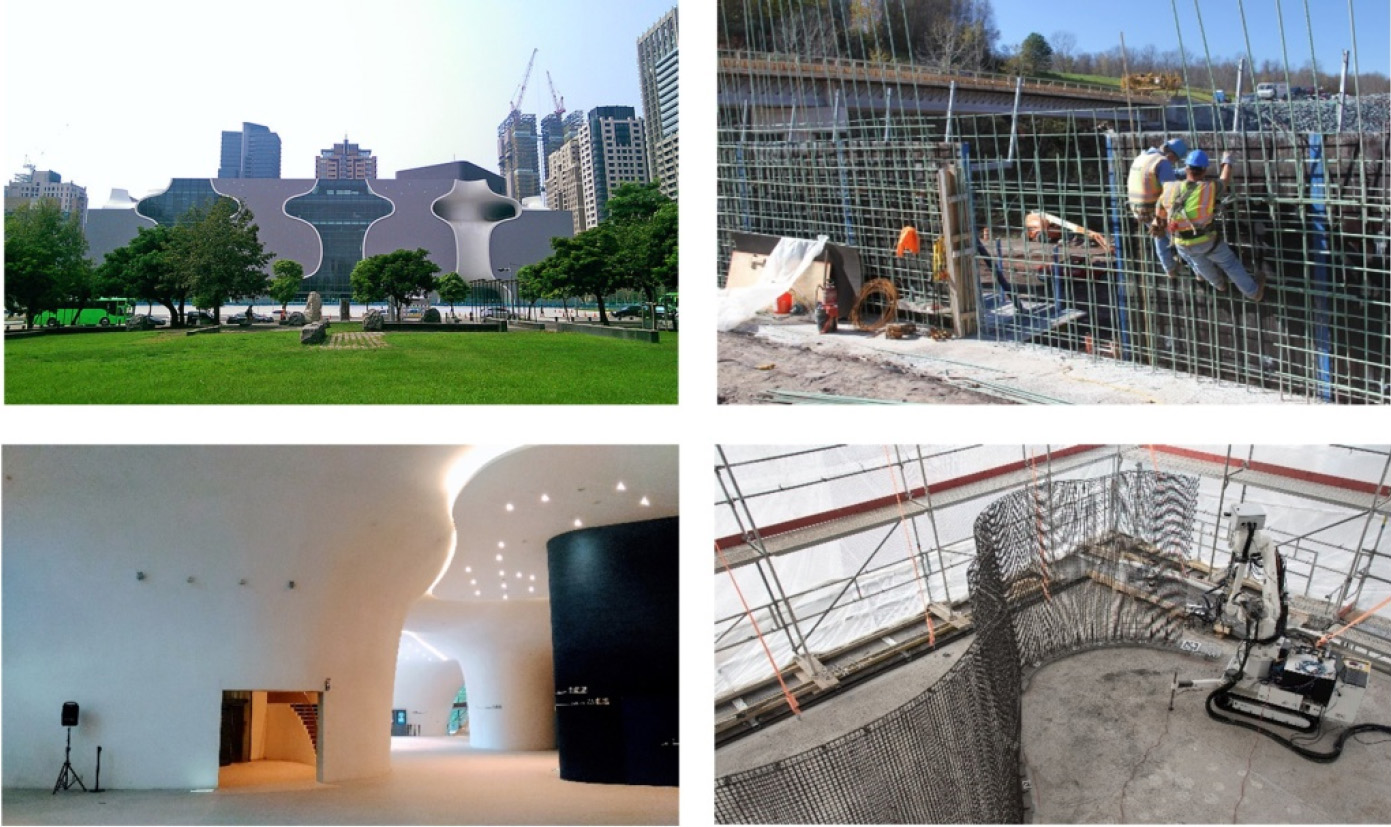
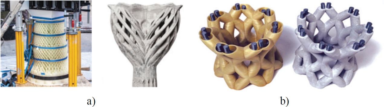
 ); right: manual and robotic rebar installation (© Gramazio Kohler Research)
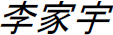
4.2.1.2. Semi-permeable fiber support
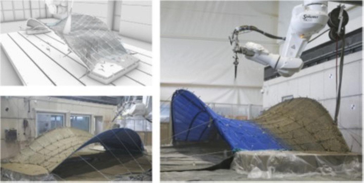
4.2.1.3. Foam support
4.2.2. Mobile support
4.2.3. Sacrificial support
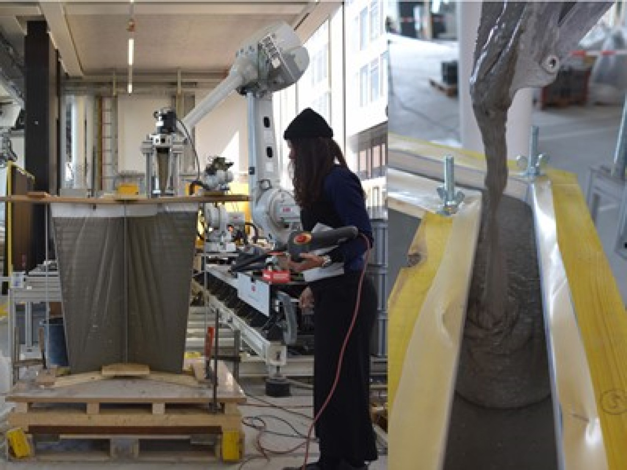
4.2.3.1. Flexible tension support
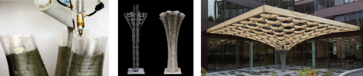
4.2.3.2. Thin polymer support (eggshell)
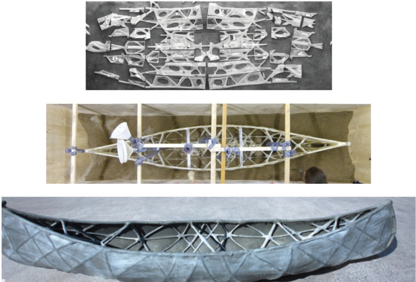
4.2.3.3. Binder-jet printed supports
4.2.3.4. Injection into a flexible support
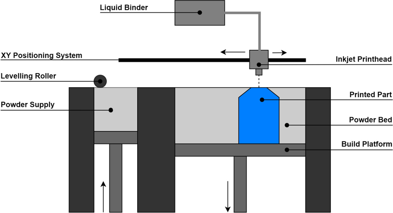
4.3. Particle bed methods
4.4. Support-free methods
4.5. Choice of process
Formwork
Alternative technique
Advantages
Limitations
Non
Shotcrete
Fast
Interlayer interface
Mechanical strength
Reinforcement
Resolution
Adhesion
Spatial control of final geometry
Freedom of form
Granular and Temporary
Selective bonding/particle bed technology
Binder jetting
Resolution Accuracy
Shape complexity
Spatial control of final geometry
Anti-gravity process
No internal stresses
Porous/lightweight structures
Heterogeneous penetration and hydration
Mechanical resistance
Anisotropy
Reinforcement
Time
Permeable, lost and permanent
Mesh Mold, Knitcrete, aerocrete, eggshell
Final geometry
Spatial control of final geometry
Fibers
Robot synchronization (reinforcement and concrete)
Rheology and mesh size
Gravity
In motion and punctual
Smart dynamic casting
Structure sizing
Spatial control and surface appearance
Fibers
Metal reinforcement
Form enhancement
Stress or deformation imposed on the material
Friction
Suitability for hydration
Weight of formwork on articulated arm
Fluid and temporary support
Injection
Lightweight structures
Shape complexity
Anti-gravity process
Suitability of injected fluid and carrier fluid
Inter-layer (presence of carrier fluid)
Physicochemical compatibility of the two fluids
Post-treatment
4.6. Prospects and opportunities
4.6.1. Dissolvable temporary supports
4.6.2. Selective binding of aggregates with foams
4.6.3. Structural reinforcements
4.6.4. Functionally graded materials
4.7. Conclusion
4.8. References
Note