Daylighting design starts with an understanding of the sky. An overcast sky has a luminance that is 3 times brighter at the zenith than at the horizon (Figure 21.1). An overcast sky is also equally bright in all directions. This equal brightness feature is the result of water vapor scattering all wavelengths of light all over the sky. Because all wavelengths are scattered the sky appears white. A clear sky is 10 times brighter in the area around the Sun than it is in an area of the sky that is opposite the sun in the sky (Figure 21.2). The clear sky is blue because the nitrogen, oxygen, and carbon dioxide molecules that make up our atmosphere scatter the higher energy blue wavelengths leaving the rest of the spectrum to penetrate through without any scattering (Moore 1985, 30–32).
Our eyes evolved under daylight, so it is not a surprise that daylight provides high efficacies. The efficacy of the Sun and sky is 100–150 lumens/watt. Incandescent light is 20–40 lumens/watt. Fluorescent light is 50–80 lumens/watt (Moore 1985, 30). Daylight has a high amount of visible light in relation to the total amount of thermal heat involved.
The solar spectrum starting from the high energy side has an ultraviolet part, a visible part, and an infrared part (Figure 21.3). Our eyes are designed to see the visible part from blue through green, yellow, and red. When all of these wavelengths are combined together as they are in daylight our eyes perceive this as white light. The ultraviolet part of the spectrum has high energy and causes materials to fade. The infrared part of the spectrum is felt as thermal heat.
Clear glass allows the entire solar spectrum through the glass. This energy hits interior surfaces and furniture, heating them up. These interior surfaces then reradiate infrared energy at a much lower energy level than the solar spectrum. Regular clear glass is opaque to this room infrared radiation. The result is that the room infrared is absorbed by the glass as if the glass were a black wall. Some of the energy returns to the room, and some of the energy goes back outside. Double glazing reduces this heat loss to the outside (Figure 21.4).
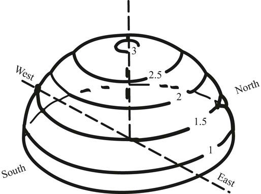
FIGURE 21.1 An overcast sky is three times as bright overhead compared to the horizon and is equally bright in all directions because clouds scatter all the frequencies of light around the sky.
Source: Moore 1985.
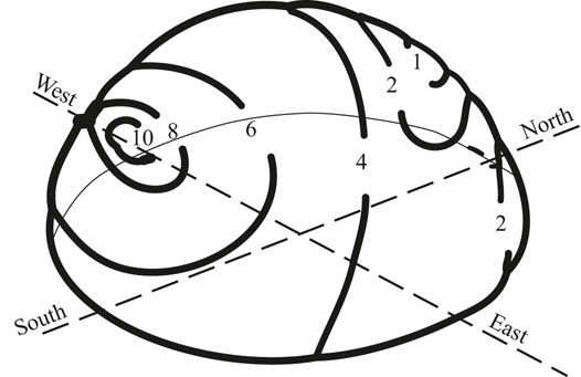
FIGURE 21.2 A clear sky is ten times as bright near the Sun compared to locations on the other side of the sky from the Sun. The sky is blue because air molecules scatter only the blue light.
Source: Moore 1985.
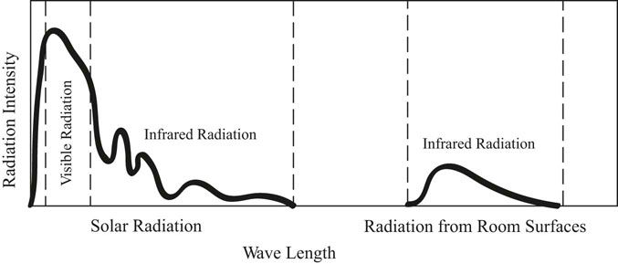
FIGURE 21.3 The solar energy spectrum compared to the infrared radiation emitted from warm room surfaces.
Source: Moore 1985.
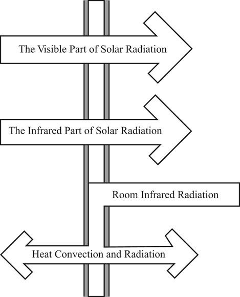
FIGURE 21.4 Radiation transfer through clear double glass.
Source: Moore 1985.
For passive solar heating in residential buildings, the selective coating that lets in the entire solar spectrum and then is reflective to the room infrared is ideal because a maximum amount of solar gain is admitted while minimizing heat loss through the window from the interior (Figure 21.5). For daylighting in commercial buildings, heating is less of an issue. The primary concern is providing lighting. The selective surface that reflects both the infrared part of the solar spectrum and the infrared room radiation allows the visible part of the solar spectrum to penetrate through the glass while reflecting the infrared part of the solar spectrum away from the building (Figure 21.6). It also reflects room infrared back into the room, which reduces the heat loss through the glass.
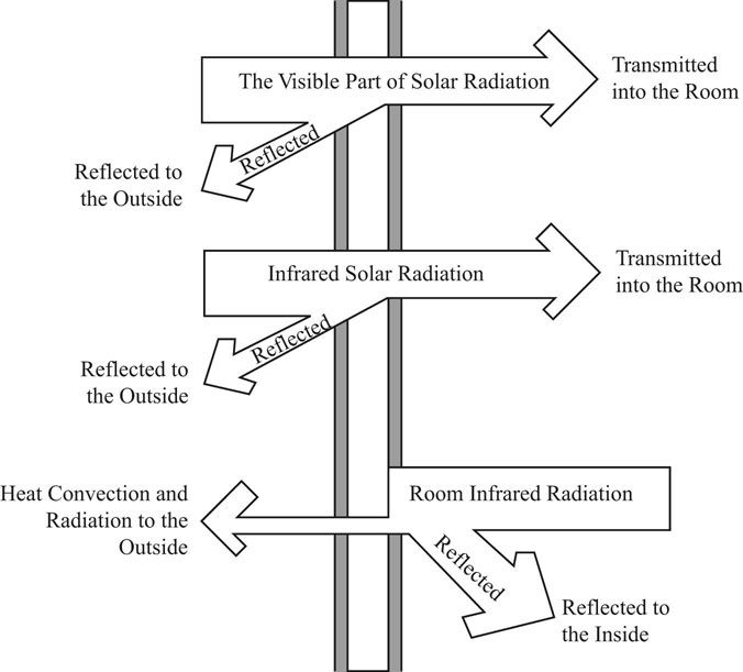
FIGURE 21.5 Radiation transfer through low-e double glass designed to maximize solar heat gain through the glass and minimize heat loss back out the glass.
Source: Moore 1985.
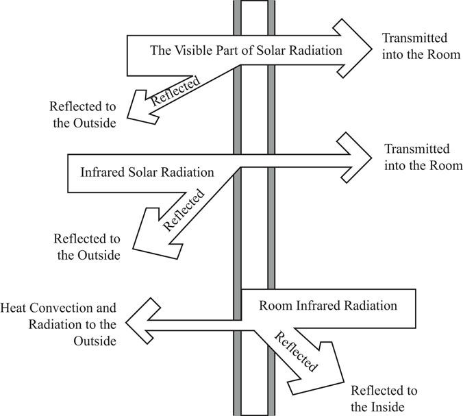
FIGURE 21.6 Radiation transfer through low-e double glass designed to maximize daylight penetration and limit solar thermal radiation transfer.
Source: Moore 1985.
Most modern glazing is doubled glazed. The double glazing adds an air space between the two panes of glass which reduces heat loss. The selective coatings are normally applied to one of the inside faces of the double glazing. In the passive solar heating case, the selective coating is best placed on the inside face of the inside glass pane where it can best reflect the room infrared back into the room. When daylighting dominates, the selective coating is best placed on the inside face of the exterior pane of glass where it can best reflect the infrared part of the solar spectrum away from the building.
Properly designed and oriented windows will allow daylighting to penetrate into a building without too much direct sun penetration. However, to save electric lighting energy, there needs to be an automatic dimming system. As the daylight is available to illuminate the areas near the windows the electric lights need to be dimmed. People do not get up from work to dim the lights.
If the design uses regular clear double glazing, there is an energy savings associated with daylighting, but the heat loss in winter and the heat gain in summer limit the amount of savings. The optimum glass area for daylighting is only 10 percent of the wall area.
The heat loss and heat gain that increase as the window area increases can be reduced by using low-e selective coatings on the glass, by shading the glass from excess summer solar penetration, and by avoiding east and west glass. The largest drop in overall energy use from daylighting comes from the introduction of double glass with a low-e selective coating. This is because heat loss through the increasing window area increases faster than heat gain. However heat gain is harder to control than heat loss. The addition of horizontal shading is the primary means of reducing heat gain. It is easier to control direct solar gain if all the glass is on the north and south elevations. The north windows receive only diffuse skylight and the south windows can be easily protected from direct solar penetration with horizontal overhangs and interior blinds. This change flattens the optimum curve (Figure 21.8). Note that the optimum glass area for daylighting is 15 percent of the wall area.
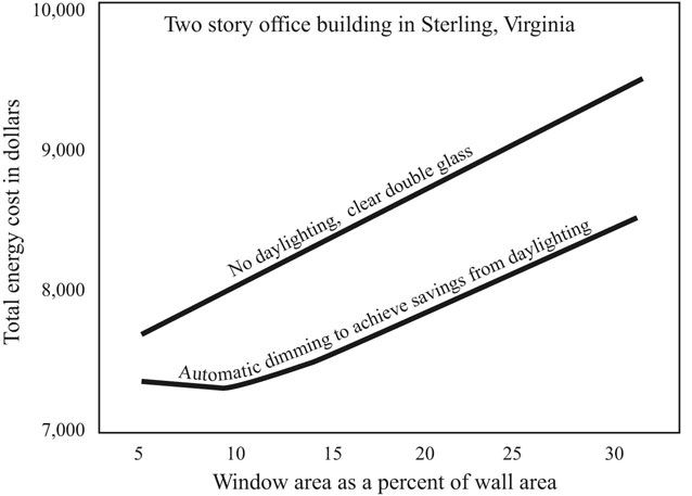
FIGURE 21.7 Energy savings from daylighting with regular double glass.
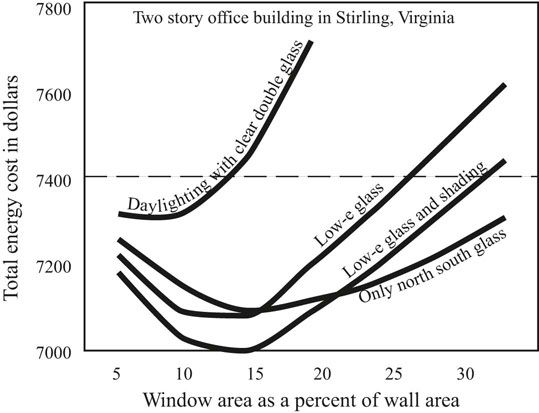
FIGURE 21.8 Energy savings from daylighting using double low-e glass, double low-e glass and horizontal overhangs for shading, and double low-e glass with shading and only north and south glass. The dashed line across the plot represents the energy use of an insulated wall with no windows in it.
The dashed line that runs across the graph of the daylight simulations represents the energy cost of an insulated wall with no windows in it. Where the optimum daylighting curves cross this line represents the window area that can be in an insulated wall that has the same energy cost as the insulated wall without any windows. Windows provide benefits other than daylighting, including views out, which provide a restful distant view and a connection to changing outside weather conditions. Operable windows can also provide natural ventilation. Thus window areas of from 15 percent to 35–40 percent of the wall area provide good energy performance.
Another way to look at the issue of how much glass area is appropriate for daylighting is to look at the growth of energy cost savings as the ratio of window area to wall area increases. As the window area approaches 35 to 40 percent of the wall area, the energy cost savings from daylighting reach a diminishing return (Figure 21.9). Window areas beyond this range will not improve the energy performance of the building. The energy codes like ASHRAE 90.1 list appropriate window area as a range from 20 to 40 percent of the gross wall area.
In the daylight literature, a quantity referred to as the daylight factor is used to indicate interior daylight levels. The daylight factor is the ratio of interior illumination divided by the exterior illumination. For example, if an interior illumination is measured as 50 foot-candles and the illumination outside is measured as 1000 foot-candles (50/1000) will produce the decimal fraction 0.05. The daylight factor is usually listed as a percentage, so 0.05 would be listed as 5 percent. The interior illumination is 5 percent of the exterior illumination. The advantage of this method is that, once the measurement is made, illumination levels can be extrapolated to brighter and darker skies by multiplying the daylight factor times the outside illumination level (Hopkinson et al. 1966, 17).
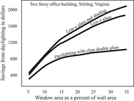
FIGURE 21.9 The increase in energy savings from daylighting as the window area is increased from 5 to 35 percent of the wall area.
An overcast sky is white and equally luminous in all directions. It is three times brighter at the zenith than at the horizon. In an overcast sky there is no worry of direct sunlight penetrating into the work space. However, the area right next to the window will be much brighter than areas deeper into the room. This can create a glare problem near the window. The solution is to provide a light shelf to lower the illumination near the window and slightly increase the illumination deeper in the room. A clear sky is 10 times as bright in the area around the Sun compared to the brightness of the sky opposite the position of the Sun. As the day progresses, the brightest part of the sky moves from the east through the south to the west. The direct sunlight is even brighter. Direct sun needs to be blocked and or bounced into the room. A partly cloudy sky needs to be considered a clear sky for design purposes because direct sun will pop into play periodically. In all cases light shelves improve the situation (Figure 21.10).
Light shelves should be one-third outside the window and two-thirds inside the window on a south exposure. The outside portion should create a 25 degree cutoff angle from high summer sun. North exposures only need the interior part of the light shelf, which will reduce excess brightness near the window. East and west exposures should be avoided but if necessary can be similar to the south exposure. The level of the light shelves can and should be coordinated with the level of direct indirect light fixtures.
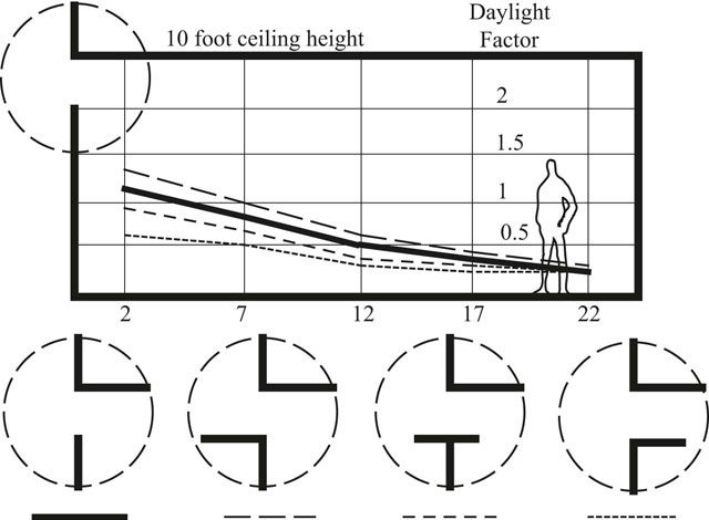
FIGURE 21.10 The effect on interior light levels of interior and exterior light shelves.
Source: Moore 1985.
Daylight can penetrate into an office area about two times the window height. The height is measured from the working plane, which is the desk height above the floor, usually 30 inches. Daylighting is about illuminating the working surfaces not the floor. There need to be layered controls to control Sun penetration and overly bright skylight near the window. These controls are often a light shelf to reduce the amount of daylight near the window and bounce some light deeper into the space, and blinds inside the window to provide personal control of the amount of light admitted. The walls and ceiling need to be white or a very light color so that light easily reflects around the room. The electric lighting needs to be wired together in parallel bands so that the lights near the window can be dimmed more than the lights further away from the window. The dimming needs to be automatic and continuous, driven by photocells that measure the illumination on the desk surfaces. The photocells reduce the amount of electric light when daylight is capable of providing illumination.
Useful daylight will penetrate into a room to a depth of approximately two times the window height (see Figure 21.11). This calculation should be made from the working plane, desk height, 2.5 feet above the floor.
Light from above frees up the orientation of the building, and can bring daylight deep into the interior of single height spaces. Skylights can be translucent or use baffles to control direct sun penetration, unless they slope far enough to the north so that direct sun never strikes the skylight. A south orientation produces a warm and variable light while a north orientation produces a blue more stable light. The light coming in through a skylight can be spread around the room with reflectors placed under the skylight (Figure 21.12). The Kimbell Art Museum in Fort Worth Texas uses this principal to illuminate the underside of concrete vaults from a strip skylight along the peak of the vault. Another method of controlling the light coming in through top lighting is to design baffles that intercept the direct sun coming in. The baffles should be white to redistribute diffuse light into the room.
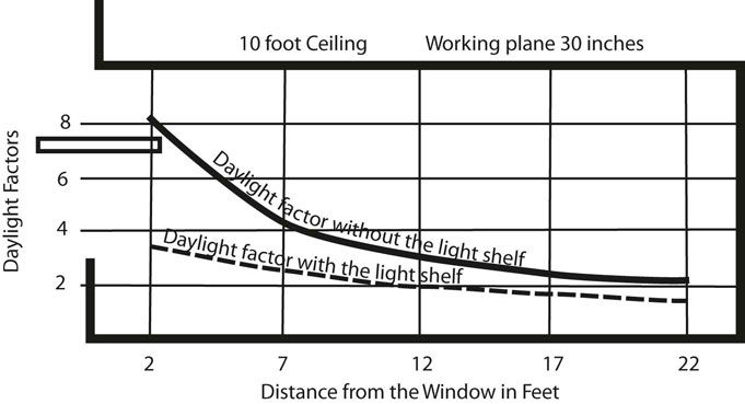
FIGURE 21.11 Daylight factor illumination levels for a 22 foot deep room with 10 foot ceilings with and without a light shelf.
Source: Moore 1985.
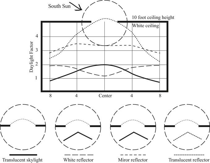
FIGURE 21.12 Reflectors can be used under skylights to distribute daylight around the room.
Source: Moore 1985.
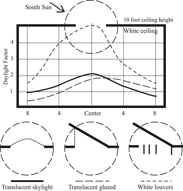
FIGURE 21.13 White baffles can be used to block direct sun penetrating from south facing monitors and distribute light in the interior.
Source: Moore 1985.
In his book Concepts and Practice of Architectural Daylighting (1985), Fuller Moore illustrates multiple ways to construct baffles on varying skylight types (Figures 21.13 to 21.16).
The Menil Collection Art Gallery uses baffles below a skylight roof to provide an even, diffuse illumination. The heating and cooling comes out of the floor, so no ducts need to be at the ceiling level, which would interfere with the diffuse lighting.
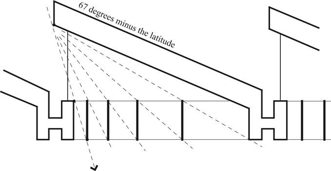
FIGURE 21.14 The construction of baffles to block direct sun penetration through a vertical south facing monitor.
Source: Moore 1985.
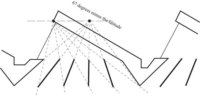
FIGURE 21.15 The construction of baffles to block direct sun penetration through a sloping south facing monitor.
Source: Moore 1985.
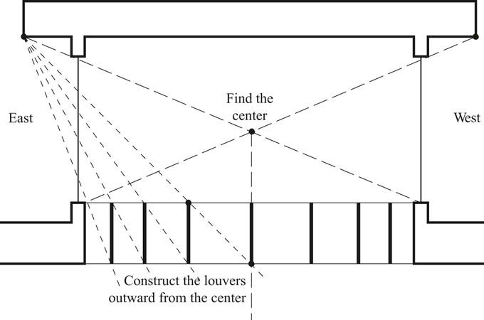
FIGURE 21.16 The construction of baffles to block direct sun penetration through a vertical east west facing monitor.
Source: Moore 1985.