FIG 8.0 (chapter opener) Expressed services coordinated with a timber hybrid glulam structure on a CLT soffit for International House, a trend-setting commercial office precedent in Sydney (by Tzannes Associates, 2017). More so than other forms of construction, the issues around design and procurement discussed here are closely interrelated with CLT use, due in part to the relative inexperience of the industry (in the UK and other English-speaking regions), from consultants to contractors, an expanding supply chain and associated issues of technical uncertainty and risk (whether potential or perceived).1 Stage 2 is the time to agree, and importantly sign-off, the architectural concept and engineering strategies, recognising that subsequent changes may be disruptive and compromise efficiency. Changing to a CLT structure at later stages will fail to realise many of the advantages of having adopted such an approach earlier (but is not uncommon). This stage is a good time to review and communicate the benefits of CLT use to ensure they can be realised wherever appropriate. If not already in place, a detailed design responsibility matrix should considered with appropriate experience and inputs sought as required. The coordination of detailed engineering strategies (structural, servicing, acoustics and fire being the most relevant) with the architectural model is fundamental, as is optimising the design for manufacture. This will inform the cost and reduce subsequent risks, particularly when design responsibilities for such elements may change to suit a building contract. For this reason, teams may also wish to record further detail as to why decisions are made or particular approaches are adopted to avoid ambiguity should others become involved. Doing so can help prevent value engineering becoming simply cost cutting when the full benefits of CLT use are not understood. Well-developed BIM models and the use of benchmarks and mock-ups can help. Key deliverables for CLT projects will include coordinated designs for services installations and penetrations, typically ahead of those required for conventional builds. The RIBA Plan of Work advocates completing all the design information for manufacturing and construction before the end of Stage 4. Accordingly, the impacts of differing procurement strategies on design intent, information production and coordination (frequently most obvious in terms of building services) should be clearly communicated and understood by the project team and client and this is where previous experience or early stage collaboration can have great impacts. Design and coordination responsibilities for all pre-manufactured elements will need to be revisited, allowing sufficient time when working back from the information required for panel manufacturing. Any design responsibility matrix should be reviewed and all parties should agree that unless exceptions are defined, and then carefully managed, the scheme for construction is frozen at this stage. Where information is required before the full completion of a stage, teams should be very clear about tasks required (and outstanding) and the responsibility for all associated deliverables.3 The following considerations are not exhaustive and project priorities will no doubt vary depending upon location, team experience, sector, form of procurement etc. This may include ensuring that material choices are appropriate to the intended function and likely form, addressing brief requirements or site conditions and that where possible the benefits of the material use are realised fully, accounting for issues of delivery cost, programme and long-term value. Consider using CLT for its own strengths and characteristics rather than simply replacing another material and do not use it where it makes more sense to use other materials – it is certainly not appropriate for all circumstances or situations. Avoiding significant spans (greater than 6.5m) and unnecessary materials use to areas where it may not be required (such as panels with large openings) will improve efficiency as will rationalising load paths, aligning functions and elements vertically and minimising transfer structures, typically more so than with other forms of construction. The UK government’s construction and industrial strategies emphasise the benefits of collaborative working with early contractor and specialist engagement. The input of experienced others pre-contract is typically of enormous value – a recurrent theme in case study projects. Specialist contractors and suppliers will likely be available to contribute and many manufacturers offer design and consultancy services. Roles and design and coordination responsibilities for all pre-manufactured elements will need to be developed and defined, allowing sufficient time working back from the information required for panel manufacturing. In the case of CLT projects there will be likely related challenges due to differing specialist design responsibilities. A structural engineer may produce initial designs, for this role to be passed to a subcontractor (or their specialist timber engineer) and building services strategies may be insufficiently well advanced or detailed to provide appropriate information to manufacture panels. It is not uncommon for late inputs from a services subcontractor (not forgetting any necessary coordination) to delay the manufacturing of panels. CLT specific roles and responsibilities to address on any pre-tender design responsibility matrix should consider design, detailed design and construction information responsibility, (including any checking requirements of subcontractor proposals) for fire stopping and protection – a fire safety specialist should be included and moisture management planned – both during superstructure erection and during subsequent site works to handover and the design of connections between structural elements, particularly if complex/non-standard or intended to be fully exposed. Regarding design of interfaces between different elements – the detailing of hybrid forms (beyond full CLT) can increase requirements from designers very significantly and this should not be overlooked. The use of BIM throughout the design process promotes collaboration, allows the rapid design iteration and optimisation of CLT use and can improve costings. There is the potential to link to other tools such as finite element analysis software and it will assist the detailed cross-discipline design coordination necessary through to information for manufacturing. Looking ahead, BIM may also be used for 4D planning of logistics and works on site (with attendant efficiencies as well as time and safety benefits for follow-on trades) and ultimately provide a detailed record of CLT components used, ensuring a building remains a well-understood asset regarding future adaptation or the reuse of components rather than becoming a liability over time. All such bodies are inherently conservative and must be engaged well in advance of any final decision or sign-off required. All will have a view of CLT use and few will view it favourably unless specific conditions are met. The team may need to work together to understand and address concerns raised and this is another area where early collaboration can pay dividends. Fire and safety issues are addressed elsewhere but prominent issues may include: durability and moisture management (see below); rigorous site management and the inspection of works; compartmentation; voids and the continuity of barriers and issues beyond life safety (such as repair after damage). Extra care should be taken where there is legislative ambiguity or uncertainty around particular aspects of a materials use. Beyond addressing negative concerns and risks, consider positive impacts of CLT use that may appeal such as the need for better and earlier coordination of designs, additional measures that may reduce risks or improve safety, the benefits of improved quality and certainty of what is being installed (with CLT, you get what you draw) and the reduced need for on-site decision making and ‘fitting’. Durability risks due to moisture damage are a significant challenge, one of the key issues for CLT use, and are almost always underestimated. Beyond considerations of the planned construction sequence to allow sufficient drying of moisture before being sealed up, any areas of potential water or moisture ingress or collection in use pose a risk to CLT elements if undetected over time. If CLT gets wet and stays wet, it will likely decay. This issue has the potential to cause huge problems during the lifetime of a building and MUST be considered and addressed through design, construction and use. Particularly vulnerable areas include ground floor/lower level CLT interfaces, end grain exposure to the edges of panels, envelope detailing and penetrations where unseen failures may compromise internal elements, flat roofs where failed membranes/waterproofing layers and subsequent leaks may go undetected and terraces, for similar reasons. Counter measures may include end grain sealant for temporary site protection of panel edges, using breathable elements and insulation where possible, considering other structural materials for flat roofs or incorporating shallow pitches to all slabs with drainage or ventilation zones above panels (especially for warm roofs). Consider partially open joints to ‘flat’ panels laid to shallow falls or incorporating multiple small perforations to panels forming roofs or below wet service installations (such as WC areas) so any water penetration beyond is made apparent to occupants below (soffits perforated in sensitive areas by 10mm weep holes may be preferable to unseen leaks above panels). CLT has relatively low thermal conductivity (c.0.13W/mK) and given its potential to cantilever, it may be tempting to continue floor panels from internal to external areas, forming terraces or balconies while minimising cold bridging. Unless there is a well-managed, robust and continuous layer of protection, such as that to a continuous shallow pitch roof, possibly with weep holes, such arrangements are best avoided. This is because damage or failure of protection to external areas might compromise the integrity of internal CLT elements, particularly floor elements which are typically more difficult to protect, ventilate or inspect.4 Beyond manufacturers’ guidance, the (UK) Structural Timber Association publish extensive guidance around issues of durability and moisture control and further discussion is included within Chapter 12. Alongside durability and fire issues, acoustic challenges are a critical issue when designing with CLT (typically due to the material’s lightweight nature). The most successful projects consider and define such issues early on and integrate solutions though design development in collaboration with specialists. Test data from manufacturers or previous projects can be particularly useful when available. Values typically vary between producers but CLT generally offers much tighter general tolerances than other materials. Whereas dimensions of concrete elements may vary as much as +/- 25–30mm, geometric tolerances for CLT panels may be as low as +/- 1–2mm by default. Similarly, the size or positions of openings can be tightly controlled with similar comparative values for CLT products, compared to similar figures as above for large openings in concrete.5 Such unprecedented accuracy for setting out of panels and apertures provides less opportunity for error which is good for fire stopping, acoustics and air/weather tightness as well as better coordination with external elements such as cladding, reveal linings or service penetrations. These are however not dimensions most constructers would recognise on a building site and whilst they may seem almost magical, the tolerances and geometric variations of all other elements and materials at interfaces, connections etc will be much greater (i.e. normal for in-situ or site work) so designs will likely have to accommodate much greater variations if incorporating hybrid structures or interfacing with concrete slabs or other construction. Concealed connections and panel joints are cheaper and simpler to make (as are non-visual grade panels), exposed panels joints less (as the cost of visual grade panels also increases). Greater complexity of connections and interfaces to exposed areas or hybrid elements may result in additional cost and design commitment and may impact manufacturing design time in complex cases. CLT is generally deemed airtight but tapes, sealing compounds or isolation strips may be required between panels for airtightness, acoustic or fire performance purposes and will require particular consideration when exposed. Strategies should be agreed with consultants before detailed design is begun. Global demand for CLT has never been greater and since CLT is custom manufactured on demand, no stocks or buffers are held. One recent large project in London has procured and taken delivery of CLT floor elements months in advance of them being required, to an off-site location before preparatory site works are complete in order to secure sufficient production capacity. A number of references are included throughout this book to illustrate that further guidance and detailed technical data are widely accessible to project teams, as Figure 8.10. Such sources can be invaluable when considering general approaches and likely performance of elements, but teams should bear in mind that any performance data or assumptions (especially regarding fire or acoustics) will likely be derived from limited tests with very specific material combinations. All figures and data should be investigated thoroughly and many projects will require bespoke calculations and possibly testing. FIG 8.10 Example extract from manufacturer’s technical literature, indicating typical wall build-up with key building physics/environmental performance criteria.
CHAPTER 8
DESIGN AND PROCUREMENT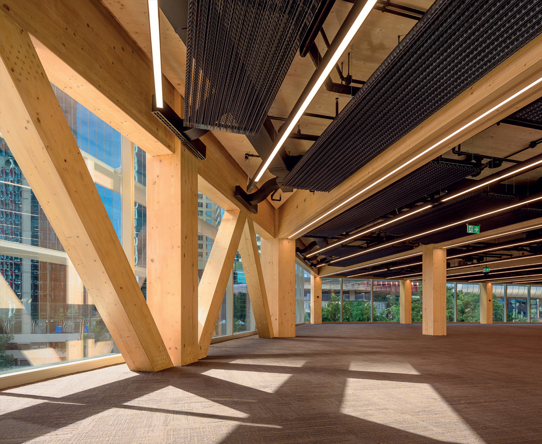
RIBA PLAN OF WORK STAGES
Stage 2: Concept design
Stage 3: Spatial coordination
Stage 4: Technical design
KEY ISSUES
Appropriate design
Collaboration
BIM benefits
Insurers, risk managers, warranty providers and building control
Moisture management
Acoustic strategy
Tolerances and interfaces
Connection and joint design
Accessories
Supply capacity and manufacturers data
