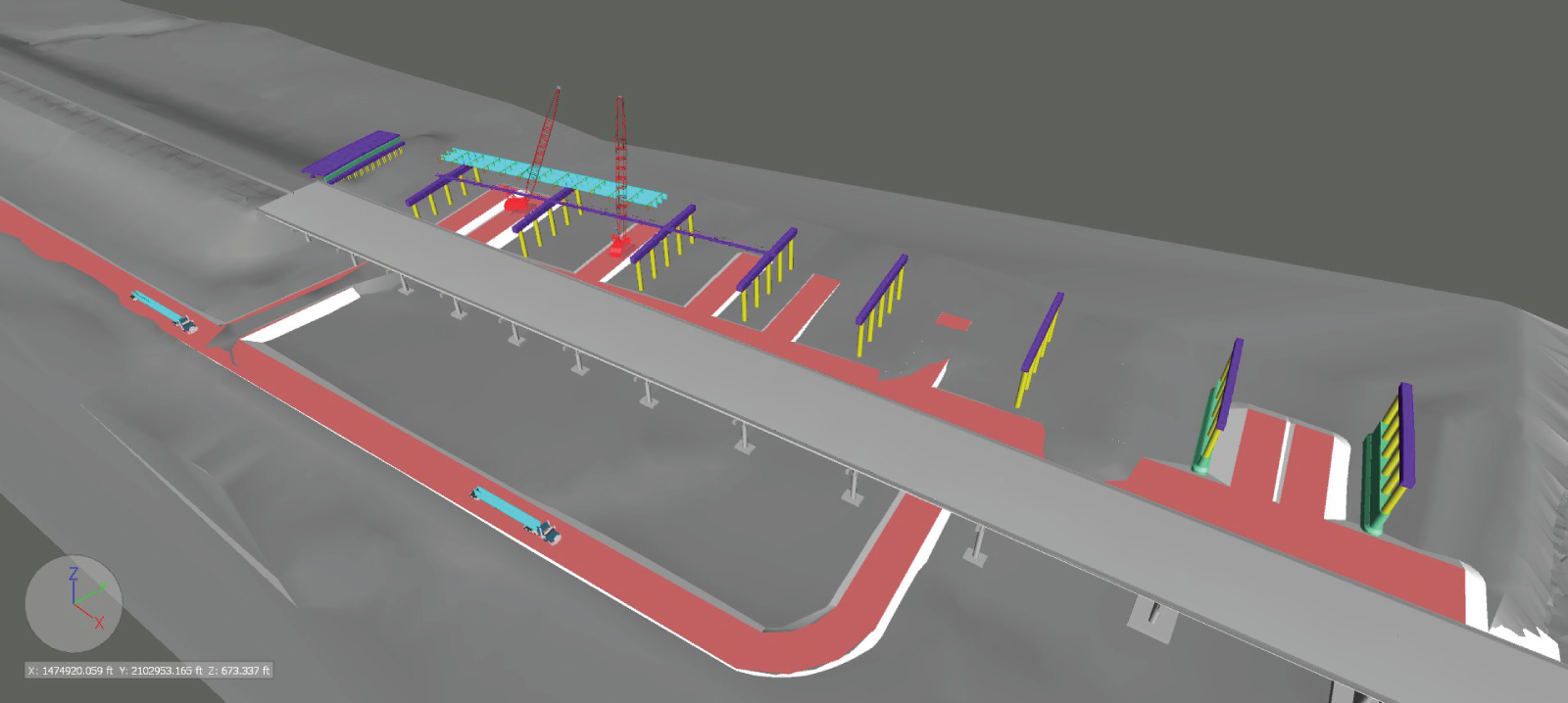
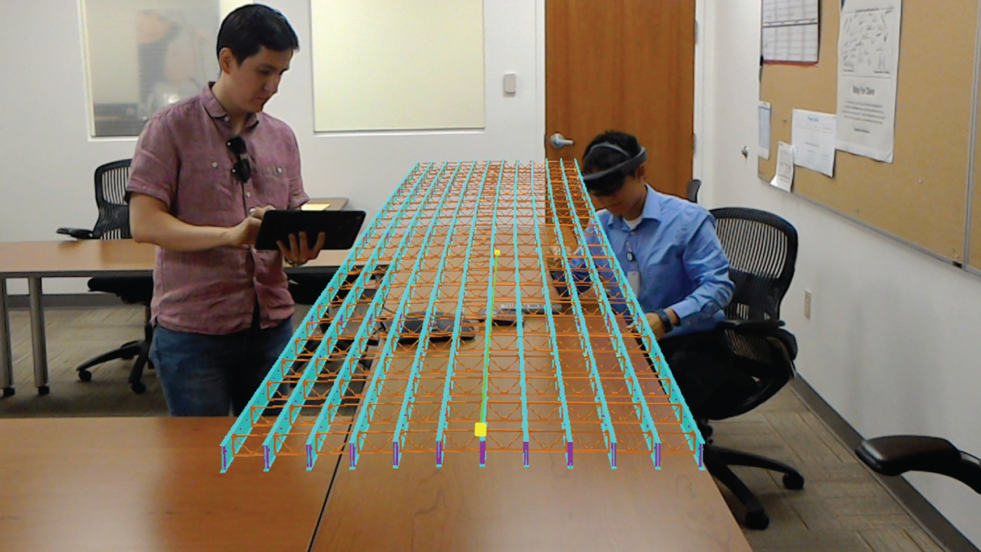
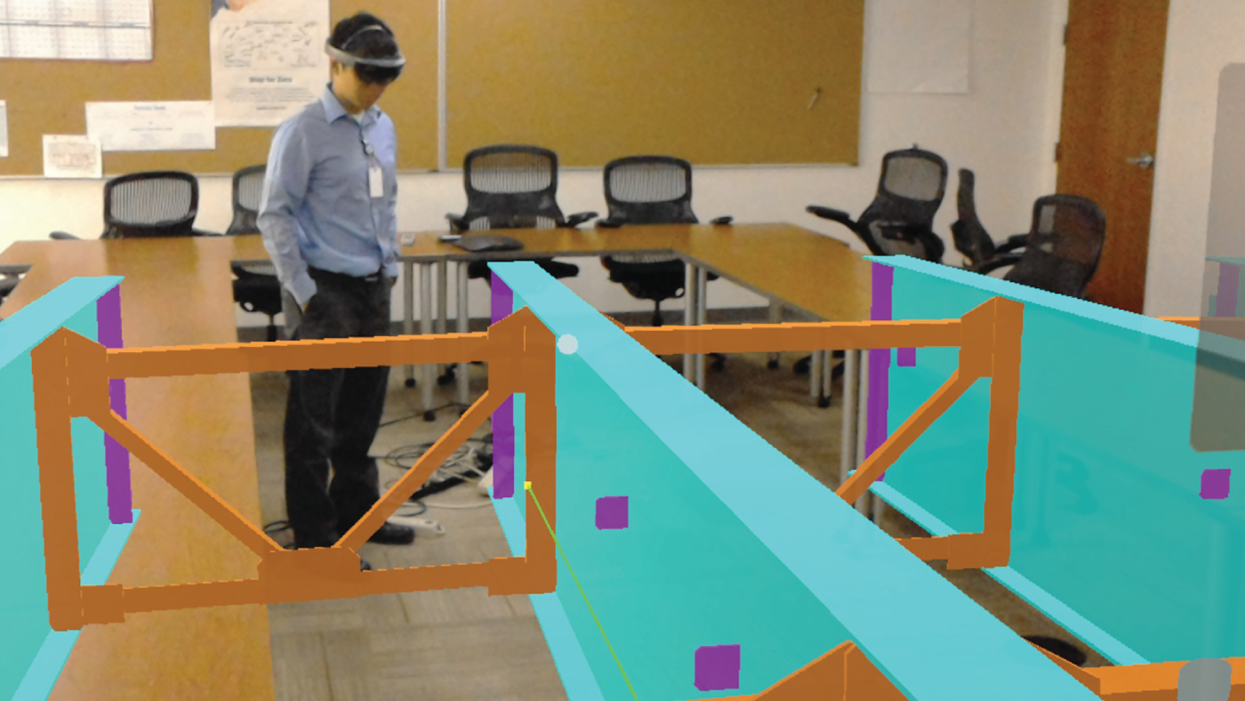
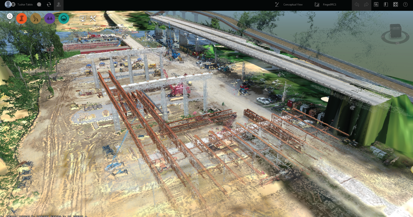
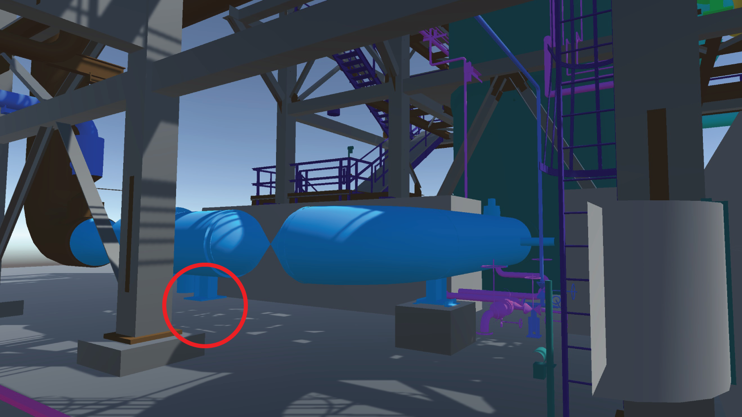
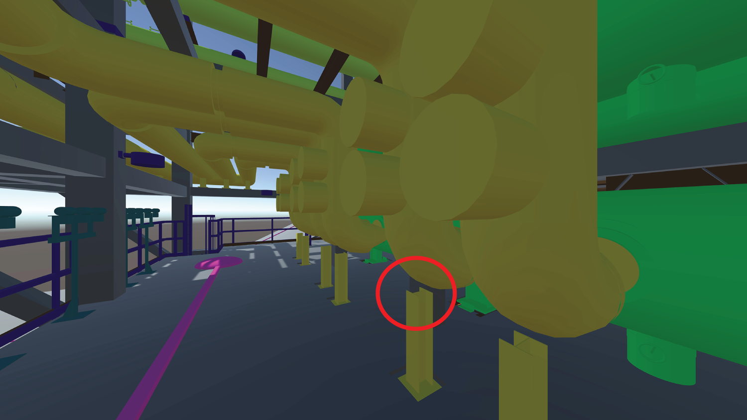
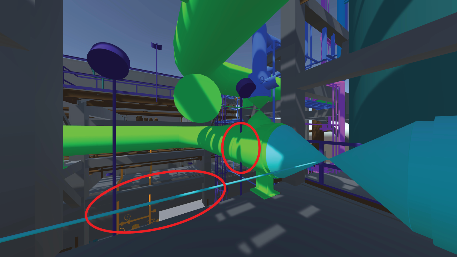
Much of what has been described so far is based on experiences in commercial construction projects. However, many of the concepts and processes apply broadly across sectors and even beyond design coordination per se. Hence, this chapter will aim at illustrating such breath. This chapter describes how other industry sectors, namely heavy industrial and infrastructure, have been or can better take advantage of building information modeling (BIM) for design and field coordination. Given that most of the work in BIM-based design coordination has been focused on commercial construction, this chapter will be dedicated to emerging applications of BIM-based design coordination in other sectors: heavy industrial and infrastructure. The goal is to show that the concepts discussed in previous chapters are transferable to other sectors as well as to other functions, such as field coordination. It is important to point out that the term BIM is often not used in other sectors. In the infrastructure sector, the terms civil information modeling, BIM for infrastructure, and civil integrated management (CIM) have been used. They all are roughly related to BIM and will be discussed in more detail in section 8.2. In the industrial sector, the most common term that relates to BIM is simply 3D modeling. But when using the term 3D modeling, it is understood that it means geometry and attribute data. This will be discussed in more detail in section 8.3. The sector that seems to be most lagging behind in terms of BIM implementation—at least in the United States—is the infrastructure sector. For most projects, state Departments of Transportation (DOTs) typically still use paper or electronic documents to manage information during project delivery and into maintenance and operations. The electronic information is managed in either commercial or custom developed standalone systems, but usually is not integrated among different functional areas of DOTs, which hinders asset management. A few DOTs have made efforts to integrate data within their systems, and some have been leveraging BIM for design review, coordination, construction sequencing, and communication with various stakeholders. However, the current state-of-practice is currently lagging behind other sectors and is inconsistent with the rapid advances in digitization across the entire architecture, engineering, and construction (AEC) industry. For the infrastructure sector, BIM and digitization, in general, can potentially help transform traditional business processes and enhance project productivity through gains in efficiency. As mentioned in the introduction, in the infrastructure sector, the terms civil information modeling, BIM for infrastructure, and civil integrated management have often been used instead of BIM. The term civil information modeling refers to what the commercial sector understands as BIM—the process of generating and managing digital representations of the built environment, which include both physical and functional characteristics of facilities (National Institute of Building Sciences 2007). The term civil integrated management, on the other hand, refers to a much broader process; it is the technology-enabled collection, organization, managed accessibility, and use of accurate data and information throughout the life cycle of a transportation asset (O’Brien et al. 2016). More recently, the term BIM for infrastructure has replaced civil integrated management. The reason for this decision at the federal level is two-fold: to better align United States efforts with international efforts in this area, and to adopt a term that is more commonly known by various industry sectors. Whichever BIM term is used, the point is that the infrastructure sector is ripe for transformation. State DOTs understand that data integration, including BIM, can help them improve work productivity. Hence, at the federal level, there has been a recent push toward developing strategic roadmaps to encourage widespread implementation of BIM for infrastructure. Delivering highway projects on schedule and within budget is one of the strategic goals of state DOTs. These agencies, along with their project partners, deliver hundreds of complex roadway projects every year. Nevertheless, the concern of delivering projects on time and within budget has been a constant challenge for DOTs in the United States. A recent study conducted for the Federal Highway Administration (FHWA) by Molenaar et al. (2018) noted that, on average, the cost growth and schedule growth during just the construction phase were 3.5% and 11%, respectively, for projects delivered using various delivery methods (e.g., design-bid-build, design-build, and construction manager/general contractor). For the worst-performing projects within the study, the cost and schedule growth were about 30% and 200%, respectively. These negative metrics are attributed to unforeseen conditions, changes in project scope, claims, and change orders and are a direct indicator of the inadequacy of project risk management (Molenaar et al. 2018); many could have been avoided with more efficient design coordination processes and, more generally, efficient data management. DOTs are mindful of the implications of cost overruns and time delays and, hence, have been evaluating improvement opportunities at all phases of project delivery, as well as operations and maintenance of their assets. Data and images related to this case study have been provided with permission from Parsons. This bid-build project, a partnership between Parsons and C.J. Mahan Construction Company, will replace the existing White River Bridge and construct roadway approaches on 1.209 miles of I-40 in Prairie County, 50 miles east of Little Rock, Arkansas. Construction began in March 2017, and substantial completion is expected in January 2020. The owner is the Arkansas State Highway and Transportation Department. This project consists of a multispan steel girder bridge over land and water, earthwork, asphalt concrete hot mix (ACHM) base, binder, surface courses, drainage structures, culvert rehabilitation, guardrails, maintenance of traffic, erosion control, concrete barrier walls, Automated Workzone Information Systems (AWIS) operation, and miscellaneous items. Construction of the new steel plate girder bridge will be approximately 200 feet upstream from the existing bridge in order to avoid interrupting highway traffic. The bridge will be 2,842 feet long by 117 feet wide and have 321.5 feet of horizontal clearance between piers. The proposed roadway will have six 12-foot-wide travel lanes with 10-foot-wide outside and inside shoulders with a concrete barrier separating the lanes. The structure spans range from 114–320 feet (approximately 35–98 meters). Self-performed work includes substructure, round columns, cast-in-place concrete pier caps, drilled shafts 8 feet, 10 feet, and 12 feet (approximately 2.4, 3.0, and 3.7 meters, respectively) in diameter and an average depth of 164 feet (approximately 50 meters), superstructure, and bridge demolition. The contractors provided and operated a concrete batch plant to produce over 45,000 cubic yards (approximately 34,405 cubic meters) of ready-mixed concrete within two miles of the project, which ensured the predictable flow of concrete to a rural job site on a busy interstate. The scope of work includes demolition of the approximately 2,800 feet (approximately 853 meters) of existing bridge, clearing and fill of new approaches, grading, a stone base, paving the new roadway, storm sewers, maintenance of traffic, environmental and erosion control, surveying, construction quality control, safety, pile and drilled shaft foundations, substructure concrete, superstructure, striping, and signage. Due to the project’s complexity, several innovative elements have been incorporated into the White River Bridge construction. To safely control the hoisting of two dozen 75,000 pound (approximately 34,019 kilogram) rebar cages from horizontal to vertical, a steel spine and lifting ring were designed and fabricated. This allowed two cranes to work together in a safe and controlled manner. BIM and 4D modeling were also implemented (see Figures 8.1 and 8.2). Schedule integration validated the plan and was a valuable communication tool. Augmented reality was also implemented in this project, giving field engineers the ability to visualize connection details using up-to-date design models (see Figures 8.3 and 8.4). Drones were used for aerial progress photos, videos, and photogrammetry (see Figure 8.5). The use of a steel trestle for the river pier allowed safer and more-predictable access by workforce and equipment, as compared to only using barges. A precast tub was incorporated into the river pier in lieu of traditional formwork. This made a critical and higher-risk element less susceptible to flooding than common methods. Concrete was placed with a double auger Bidwell placer to eliminate a centerline construction joint. This enhanced the bridge deck quality. The White River Bridge project illustrates how infrastructure projects can benefit from digitization, enabling more-advanced coordination and construction planning approaches. This enables Parsons to increase predictability and productivity in this large and complex project. FIGURE 8.1 3D modeling for the bridge and equipment was used to for site planning, including evaluation of construction means and methods, and communicating the plan to field crews through 4D animations. Source: Image courtesy Parsons FIGURE 8.2 4D BIM illustrates the schedule of activities for May 22, 2019. The image illustrates completed and planned deck pours, caps, and columns. Source: Image courtesy Parsons FIGURE 8.3 Field engineers using augmented reality for a design Review Source: Image courtesy Parsons FIGURE 8.4 Augmented reality gives field engineers the ability to visualize connection details using up-to-date design models. Source: Image courtesy Parsons FIGURE 8.5 LiDAR and autonomous drones ease the process of capturing real-time conditions, which can be used for inspection, planning, progress monitoring, and as-built documentation. Source: Image courtesy Parsons This case study was originally published in Sankaran et al. (2016) by SAGE Publications and has been reutilized here in accordance with SAGE’s Green Open Access policy. The project in this case study involved the reconstruction of an interchange that had seen a large increase in vehicular traffic over the years. The construction involved roadways, tunnels, bridges, retaining walls, and noise barriers and relocation of utilities. The project was chosen as a case study because of the implementation of several civil integrated management (CIM) technologies including the 3D design of terrain and roadway elements, 3D and 4D modeling of structures, and a clash-detection process. On this project, the return on investment for 3D design and clash detection was quantified, and the agency gained insightful results on empirical benefits. This project also represents the pilot effort of the agency in deploying 3D design and clash detection. During the planning phase, the agencies noted that existing as-builts and traditional surveying methods could not meet the data requirements for model-based design. Thus, the agency adopted an integrated surveying approach that involved multiple sensing technologies to assist in rapid data collection with greater coverage. In the process, inputs from advanced sensing technologies such as mobile LiDAR and unmanned aerial vehicles were systematically combined along with the data from conventional methods (such as total stations and laser scanners). After the collected data were processed, the resulting information included semantically rich and georeferenced 3D point clouds and high-resolution images. The information on utilities was surveyed through subsurface investigation techniques and confirmed through digging and sampling at selected locations. The accuracy and quality of this information were vital on this project to meet the data requirements for the 3D design process. The design of the project was shared between the agency and consultants, with the agency performing 35% of the scope in-house. The agency performed design in three dimensions for terrain and roadway elements. The design consultants and the agency collaborated with pertinent software tools and processes to produce 3D models for bridges, retaining walls, drainage, utilities, lighting, and other significant structural elements. The modeling requirements for the structural entities were regulated and standardized by using specifications for the level of detail and accuracy of the information required in the three dimensions for all the project elements (i.e., terrain, roadway, and structures). After the construction phase, the project provided valuable insights on quantifying the return on investment for CIM. The primary benefit of 3D design on this project was its model-based design coordination and clash-detection process. The 3D design models were integrated into software applications that helped identify and resolve spatial conflicts among design entities such as roadways, drainage, utilities, and other structures. As such, the agency was able to quantify the benefits by designating the cost of change orders and design issues that could have arisen in the field if the conflicts were unresolved. Furthermore, 4D modeling was also deployed to perform staging analysis and optimize the construction sequences for bridges; this process contributed to additional benefits of model-based design. A design-bid-build project, this case study supported the claim that the owner’s leadership and involvement in 3D design processes can yield significant benefits through model-based clash detection. BIM has contributed to the success of many industrial projects in recent decades. The industrial sector has been leveraging 3D modeling for design review and, more recently, construction work packaging. The idea of dissecting capital projects into smaller parts is not new, and it is one of the fundamental concepts of the project management body of knowledge (i.e., work breakdown structure or WBS). Advanced work packaging (AWP) is a planned, executable process that encompasses the work from initial planning and continuing through detailed design and construction execution. The main difference between AWP and traditional project management approaches is that AWP is a construction-driven process that requires construction participation in the early planning stages, and adopts the philosophy of “beginning with the end in mind.” The process aims at aligning engineering, procurement, and construction disciplines early in the front end planning stage. More detail on AWP is available at CII (2013). It is important to note that AWP as a process uses BIM/3D modeling, including both geometric (where work packages are extracted from) as well as attribute data, and links to external databases, such as supply chain data. 3D modeling has become the standard that almost all engineering, procurement, and construction (EPC) companies use to help plan work, correct plans when projects get off track, and modify or update plans when the project requires changes due to field conditions. The complexity of refinery, petrochemical, and other heavy industrial projects in comparison to commercial construction increases with these types of systems due to several factors including, but not limited to, the following: Therefore, it is not surprising that BIM has been a very beneficial planning and communications tool for industrial construction as a whole. BIM enhances not only design coordination, but also intra/inter-project communications, and the development of work packages to a level that could have never been realized through traditional practices. The interface it provides is as close to simulating actual construction prior to any resources being consumed as is possible with current technology. This ability to simulate construction to avoid possible construction conflicts and then use these simulations to provide work packages to crews in the field is a truly streamlined process for the effective utilization of a plan. Several large EPCs are now experimenting with different forms of visualization of their models, including virtual and augmented reality, which will be discussed in chapter 10. EPC companies use 3D modeling for all aspects of their projects; however, many apply the most rigor in modeling for pipe design and installation. This is due to the amount of pipe to be installed and the complex web of connections that it can produce on the site. This amount of attention is applied to the model to ensure that the facility is complete and constructible, and that the most efficient workflow can be achieved once the design is complete. For example, in Figures 8.6 and 8.7, which illustrate a model used for design review in an industrial plant, there are missing supports for two separate pipe spools (false negatives). Figure 8.8 illustrates a hard clash (true positive) as well as a missing fall-protection railing (false negative). The false negative issues would not have been caught in automatic clash detection, as discussed in detail in chapter 3. False negative issues illustrate the importance of “walking the model” as a complementary process to automatic clash detection. FIGURE 8.6 Missing support for pipe spool (false negative) FIGURE 8.7 Missing support for pipe spool (false negative) FIGURE 8.8 Missing fall-protection railing (false negative) and hard clash (true positive) between the lime green pipe spool and purple light fixture EPC companies typically allocate much of their schedule risk to pipe design and installation and use BIM as an effective tool to mitigate these risks and communicate construction plans to the owner, workface/craft planners, as well as installation crews. Several EPCs have been able to apply BIM to the total project life cycle for project controls. The benefit of doing so is the ability to effectively plan track and execute their work. Whether it is a walkthrough, work package development, system turnover, testing, or simulations, EPCs have been using BIM/3D modeling widely. An EPC company took on a $350 million (in US dollars) refinery upgrade project in the southern United States. The EPC was acting as the general contractor. The project consisted of two parts: a renovation of the existing refining facility, as well as an addition to the refining plant. The project included major improvements to an existing hydrocracker unit that involved connecting miles of pipe from a pipeline to two refineries. This connection allowed the two refineries flexibility to function as one. There were two phases to the construction project. During the first phase (pre-turnaround), the plant remained running. Safety was a major concern for the 500-member construction team as they worked around existing infrastructure. The owner wanted to keep the facility running as long as possible to avoid losing profits; thus it was important that the EPC complete as much work as possible before the next phase of the project. Each month the facility was closed, the owner lost $10 million (in US dollars) in profits. During the second phase of construction (turnaround), the plant shut down for 80 days and crews worked in shifts for 24 hours per day. The turnaround crew was made up of 1,500 laborers. Worker positions were coordinated and the construction schedule was planned down to the hour. Even the smallest delays were detrimental to the project’s on-time completion. Thus, the turnaround phase was integral to overall project success. The EPC originally estimated that the project would take four years to complete. However, the owner wanted the project to be completed in two years. Thus, the project was completed with an ultra-fast-track schedule; the selection of alternatives, defining the scope of work, and detailed design all occurred concurrently. The project was on schedule as of February 2017, when this case study was developed. The engineering was approximately 75% complete, and construction was approximately 35% complete. However, due to excessive owner changes, the project was suffering cost overruns. Due to the complex nature and size of the project, the EPC implemented BIM on the project mainly to help with craft planning and materials management. A large team of modelers, both in the United States and in India, managed the refinery’s BIM. The model was created in the planning phase of the project and included 3D geometric data as well as information regarding materials, quantities, and specifications. For this project, the EPC primarily used BIM to exchange data with its fabricators using piping component files. It also used BIM to support the company’s material control, warehouse, and field planning/progress. This included estimating the tons of steel, linear feet of pipe, and cubic yards of concrete needed and recording the amounts of materials used. The company believed that starting the building information model as early as possible was crucial, so it began creating the building information model for all piping and steel systems in the engineering and design phase of the project. The EPC federated models and information from all subcontractors into its in-house system. By using the federated model, the EPC was able to send out specifications and plant fabrication information. In the past, this process was done manually, which resulted in much lower productivity. These tasks would have been much tougher to complete and would have taken longer without BIM. Each trade’s model was reviewed, and new versions of the federated model were published on a weekly basis (in a process that is very similar to what is observed in commercial construction). The BIM managers looked for problems with the consistency of the model as well as foreseeable operation, maintenance, and constructability issues and opportunities. The owner was able to view the building information model on tables daily—both in the office and in the field. The field planning and progress team used the building information model to review construction progress and prepare work packages. Once this project is complete, ownership of the building information model will be turned over to the owner. BIM was implemented on this project due to its size and the owner’s contractual requirement. Successes were displayed in many areas of project delivery beyond design coordination, including preconstruction, communication, quantity trending, fabrication shop drawings, and safety. This chapter described how other industry sectors—heavy industrial and infrastructure—have been or can better take advantage of BIM for design coordination. The goal was to show that the BIM-related concepts discussed in previous chapters are transferable to other sectors. Complete digitalization in the AEC industry as a whole is imminent, but industry sectors are currently at different levels of digitization. The infrastructure sector is generally lagging, while heavy industry has been making significant strides toward digitization; this has enabled this sector to develop more advanced coordination and construction planning approaches, since their models have been fully integrated into other project databases, such as supply chain. Digitalization of project and service delivery business processes within the infrastructure sector offers a huge opportunity to bring about significant reductions in inefficiencies and productivity gains to all stakeholders involved, much of which has already been observed in the heavy industrial sector and in commercial construction in the last decade. At the heart of this imminent industry-wide digitalization is BIM.
Chapter 8
BIM-Based Design Coordination in Other Industry Sectors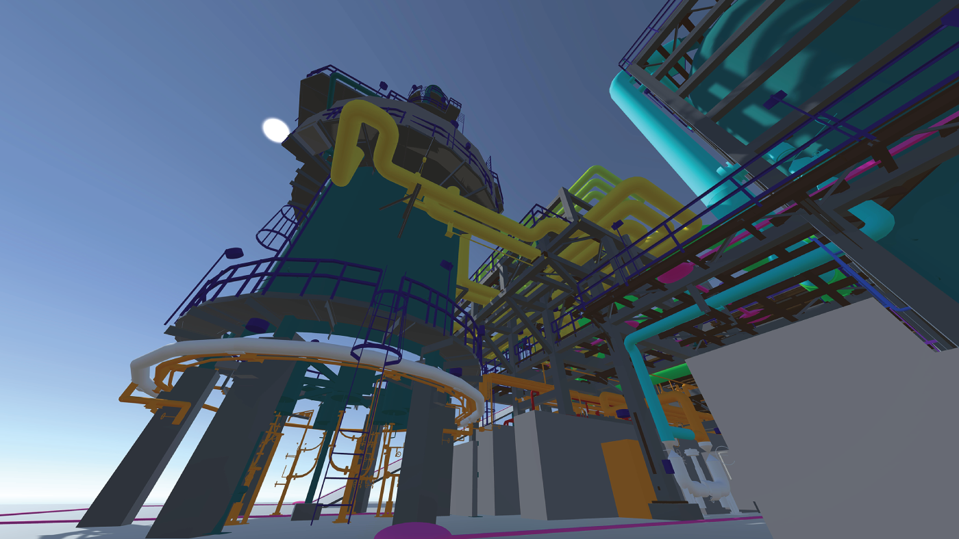
8.0 Executive Summary
8.1 Introduction
8.2 BIM-Based Design Coordination and Fields in Infrastructure Projects
8.2.1 Case Study: White River Bridge Project

8.2.2 Case Study: Reconstruction of an Interchange
8.3 BIM-Based Design Coordination in Industrial Projects
8.3.1 Case Study: Refinery Upgrade Project
8.4 Summary and Discussion Points
References