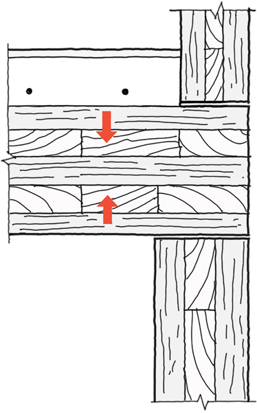
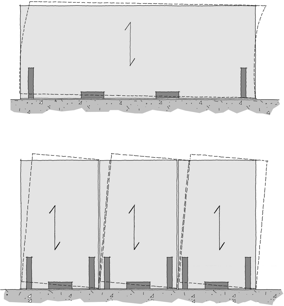
FIG 9.0 (chapter opener) The 715m2 sports hall at Harris Academy, Sutton (by Architype, 2019), was erected in just six weeks. The large format CLT panels, seen with glulam roof beams, contributed to very high envelope performance in terms of insulation and airtightness. At over 10,000m2 in area, this was the largest passivhaus project and the first passivhaus secondary school completed in the UK. In understanding the properties of CLT it is first important to understand the makeup of the raw material itself. Timber is an orthotropic material, meaning its material properties change when measured from different directions. The opposite of which (isotropic) for example would be steel where the values are the same in all directions. So, in a three-dimensional space, timber will have two axes that will have similar properties, which are perpendicular to the grain and one unique direction parallel to the grain. The simplest way to visualise the formation of wooden material is via a typical drinking straw, or a group of straws. Quite soft in two planes, but strong in the direction of the straws. When viewed at a microscopic level timber does indeed resemble a collection of straws. It is this cellular structure that gives the material both its strength and its weakness. The challenge in the design of any structure is to fully appreciate both the positives and constraints around a material and create a design that accommodates all aspects of the behaviour. Timber is therefore strong in one axis. With CLT the process of cross laying the lamella is effectively reinforcing the section with more of the same material, i.e. wood reinforced with more wood. The impact is a versatile timber panel that can be used to form all parts of a structure that is lightweight, fast to construct and sustainable. Understanding the material properties allows designers to apply any material where it will be working to its strengths and minimise the constraints. CLT is a great timber product for supporting uniform loadings e.g. roofs, office floors or residential floors. The material will however struggle with large concentrated loads such as transfer loads. They may be possible but can significantly increase sizes of the elements, have large creep deflections and generally require stiffening elements (e.g. steel). Efficient layouts can be created by maintaining a simple load path to the foundations/podium structures e.g. building setbacks to be aligned with the structural grid or wall panels. It’s not uncommon for the ground floor to require a more open plan structure to the layout. A podium to this area is quite regular and generally formed from concrete. The main driving factor for a CLT floor structure will typically be the vibration criteria to be achieved. This should be looked at early in the scheming process and can define the setting out of the structure/architecture/material volume. From a timber volume regard, shorter spans will significantly reduce the volume of material required and hence the cost. The sizes in Table 9.1 give an approximate indication of expected size ranges.1 Maximising the off-site production process will lead to a smoother construction process. Consider grids/layouts to suit the ideal transport section and reduce wastage, front load services coordination where possible and the potential to pre-install roof membranes before placing panels, reducing work and risk on site and better for durability. With accurate CNC cutting, windows might be pre-ordered for quicker weather tight envelopes. Structural openings, such as large doors and windows will tend to require a lintel of some sort as Figure 9.1. FIG 9.1 Methods of forming openings, from left to right: 1. Two-way spanning slab over openings (no lintel), 2. Wall panels with punched openings, 3. Lintel support. The two-way spanning nature of the CLT panels can be utilised over openings where the width of the opening does not exceed the width of the panel and the bearing requirements. Supporting the slab in such a manner uses the two-way spanning nature of the CLT where the inner layers perpendicular to the main span are now acting in a larger structural capacity. The floor slab panel arrangement will need to be cut to suit the locations of the openings. This type of method is best suited as a window opening where no downstand is permitted, possibly due to daylight requirements. A punched panel arrangement can be used mainly for smaller window or door openings and is subject to the width of a panel. Openings are cut to a high tolerance so fixtures can be fitted almost straight away. However, in terms of the material’s efficiency the timber cut away to create the opening needs to be included within the costs. In this case the inner layers provide the structural capacity. For high loadings the shear capacity will tend to be critical due to the reduced structural width. The majority of large openings will require a lintel support. A panel is rotated 90 degrees to form a downstand beam. The external layers are now the structural elements and offer greater capacity for the same depth compared to the punched panel arrangement. With a lintel design it is typically best practice to design the opening so the lintel and wall panel are the same thickness. This can avoid complicated finishes details and bearing issues. While CLT reinforces the stability of the product it does so in one direction only. The typical construction method for CLT is to support the floor panel by directly bearing onto the CLT wall (platform construction, as Figure 9.2). The next wall then bears onto that floor panel. This means that the building load is applied across the grain of the floor panel which is more susceptible to the displacement and to moisture drying shrinkage effects. FIG 9.2 Section through floor slab (platform style construction) indicating direction of movement when loaded. Understanding the movement of the structure is necessary in ensuring that the details’ design can be developed to either resist or allow for this change in dimension. Areas where this is particularly relevant include: Detailing for vertical movement tends to fall under one of two approaches: In limiting the vertical movement the aim is to reduce the amount of loaded perpendicular grain to the floors, so the load path becomes an end grain to end grain solution. This can be accomplished by using castellated timber walls or grout pockets. The structural analysis of a CLT element is not as straightforward as reinforced concrete slab or steel section. The structural elements of the section are the layers with the grain direction parallel to the span direction. The layers in between contribute very little to the stiffness other than increasing the lever arm between the parallel layers. In analysing the stiffness of the CLT panel a critical factor is the rolling shear in the perpendicular grain. This will need to be considered when calculating the moment of inertia (I value), as the timber fibres can ‘roll’ and create a slippage in the element as Figure 9.3. Parallel layers cannot therefore be assumed to act in a fully composite manner. This leads to a counterintuitive situation where the longer the floor spans the more composite the section becomes. This is due to the area of the perpendicular layers increasing longitudinally and hence there is more resistant to rolling shear forces. FIG 9.3 Floor panel section indicating potential for fibre rolling effect of intermediate layers (cross lamella) when loaded. There are several methods of calculating such properties, however the most common is the ‘Gamma method’ where an approximation of the shear deflection is calculated. Annex B in BS EN 1995-1-1 gives guidance on the calculation of a mechanically jointed beam.2 This gives a method of calculating the slip in between the joint members called the Gamma value. This value is based on the slip modulus of the fastener which it assumes is either a screw, bolt, dowel, staple etc. On this basis, the sectional properties of the CLT panels can then be calculated by taking into account the fact that the fasteners between the structural panels are perpendicular timbers where shear failure is critical. Once this value has been obtained it can be applied to the structural layers using parallel axis theorem to calculate the stiffness of the panels. From this, the stresses and deflections in the panel can be calculated to ensure an appropriate design. With the analysis of a beam section the layers in line with the span are taken into account during the design for moment, shear and deflection. The buckling of a beam is not usually an issue as the beam is typically restrained by the support slab. However, in certain situations this may not be the case, therefore a buckling check is required. The total width of a CLT beam may be used for the critical bending stress calculation if the outer layers are aligned with the span. If they are not, they should not be included in the buckling calculation. The analysis of walls and columns follows the same principles to that of a beam i.e. selecting the correct structural layers for strength and buckling checks. Stability to a CLT structure is typically provided by the floor panels acting as a diaphragm and directing the loads to the vertical stability wall elements. Where CLT walls provide the stability to the building, the floorto-floor heights can impact on the capacity of the walls to resist horizontal wind loads or limit building deflection. FIG 9.4 Stability wall arrangements and potential for deflection under load. Sound transmittance and soundproofing remains a key issue between uses, dwellings or areas within the same building, such as adjacent office floors or school classrooms. Timber is significantly less dense than concrete, typically around 20% of the density. Therefore, an approximately 500mm thick CLT floor slab would be required to achieve the same level of sound insulation as a 100mm thick concrete floor slab. Simply increasing the thickness of a timber slab is not often a viable solution. A better way to increase the level of sound insulation is by acoustically decoupling the elements within a separating construction. This can be achieved by the inclusion of cavities separating two mass elements and/or resilient fixings. The inclusion of an absorbent material within cavities can further help to improve the level of sound insulation by reducing resonances. Adding mass is another commonly adopted mitigation measure, this might be in the form of a screed topping over CLT slabs or dry laid high density boards, typically lap jointed, above a slab. Manufacturers usually offer detailed guidance regarding sound insulation, focusing on airborne sound (such as music or voices) and structure borne sound, including impact sound (e.g. footsteps or moving furniture). Accessory manufacturers offer separation strips that can be used to improve the acoustic performance of panel joints or fixings and test data is widely published for various elemental build-ups using different materials; this is typically reflected in manufacturers technical approval documents such as European Technical Assessments (ETA) or software tools.
CHAPTER 9
ENGINEERING ASPECTS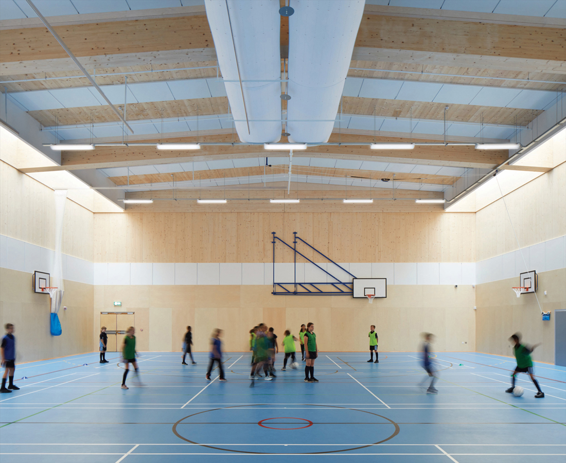
CLT BUILDING DESIGN
Structural watchpoints
Building layout
Floor spans
Building type
Typical Floor Spans
Typical Panel Depth
Residential
<5.0m
160–180mm
Education
7.5m
220–240mm
Commercial
6.0–7.5m
220–260mm
Maximise the off-site advantage
CLT FRAMING
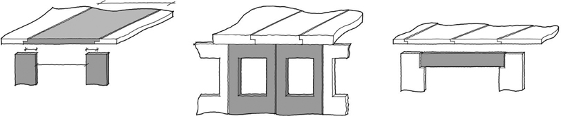
Method 1: Two-way spanning slab
Method 2: Punched holes
Method 3: Lintel
UNDERSTANDING MOVEMENT BEHAVIOUR
CLT ELEMENT DESIGN

ACOUSTIC CONSIDERATIONS