Kateryna KUZMENKO1, Charlotte ROUX2 and Adélaïde FERRAILLE3 1 Groupe Kardham, Paris, France 2 École des Mines de Paris, France 3 Laboratoire Navier, École des Ponts, Marne-la-Vallée, France The current development of 3D concrete printing technology is driven mainly by its potential to increase the productivity and formal freedom of concrete construction, as well as to reduce the industry’s costs and environmental impact. The latter, based on the ability to reduce the material content of construction elements through rational material deposition, is studied in this work using the life cycle assessment (LCA) method. The environmental model established here proposes a generic assessment framework that can be applied to all extrusion printing processes, whatever the material used. A specific separation between the impact of the material and that of the process is maintained throughout the environmental assessment carried out at the scale of the process and then of the constructive system, the space lattice wall system. The latter is then compared with its conventional analogues in the masonry and reinforced concrete categories. This shows that, despite the substantial material savings possible with the 3D printing process, environmental impact savings are not guaranteed at the scale of the constructive system, notably due to the impact linked to the process. We thus introduce the Kf coefficient, capturing the level of impact transfer from the material to the process for a given technology, and thus designing the most environmentally relevant industrial application. Concrete is the most widely used building material in the world, ahead of all other materials (stone, clay, metal and wood) (Van Damme 2018). This intense use of concrete is mainly due to the wide availability of its components, their relatively low cost and the ease with which they can be transformed into a strong, durable, structural material. Concrete is a mixture of water, sand and gravel, joined by a binder, usually cement. It is this last component, cement, which accounts for most of concrete’s environmental profile (Gartner 2004). Indeed, the preparation of 1 ton of cement emits almost 1 ton of CO2 equivalent (kg CO2 eq). Half of these emissions come from the chemical reactions involved in the decarbonation of limestone, the other half from the energy (mostly of fossil origin) required for firing at 1,450°C, the temperature needed for decarbonation (Feraille 2016). Worldwide, cement production accounts for between 5% (Gartner 2004) and 8% (Flatt et al. 2012) of anthropogenic CO2 emissions. The other constituents of concrete (gravel and sand), on the other hand, have a very low carbon footprint, even close to zero: 1 ton of aggregate corresponds to around 2.75 kg CO2 eq (Union Nationale des Producteurs de Granulats 2017). Thus, the carbon footprint of 1 m3 of concrete is approximately equal to the mass of the cement in the mix, that is, an average of 300 kg, equivalent to 300 CO2 eq /m3 (Kuzmenko 2021; Kuzmenko et al. 2022). On the scale of the construction system, numerous studies have shown that the share of traditional placement processes (by pouring) represents between 1% and 2% of the total balance (Hong et al. 2015; Li et al. 2019; Ryklová et al. 2019; Kuzmenko 2021). Thus, the environmental impact of a concrete construction element will also be defined, for the most part, by the quantity of cement in the mixture. There are two possible strategies for reducing the environmental impact of concrete construction. The first involves reducing the impact of the material itself, by substituting cement with alternative binders such as pozzolanic materials, limestone fillers or industrial residues (blast furnace slag and fly ash) (Gartner 2004; Flatt et al. 2012; Feraille 2016; Scrivener et al. 2018). The second is aimed at reducing the carbon footprint on the scale of a construction element/system, or even the entire industry, and thus proposes to reduce the overall volume of concrete use. This can be achieved by resorting to material reduction strategies and more virtuous material deposition methods, such as additive manufacturing technology aka 3D concrete printing (Gosselin et al. 2016; Wangler et al. 2016, 2019; Buswell et al. 2018; Duballet et al. 2019). In this chapter, we will study the environmental relevance of this second strategy using the LCA method, and in particular the model developed in our previous work (Kuzmenko 2021; Kuzmenko et al. 2022; Roux et al. 2022). This LCA model for 3D concrete printing technology distinguishes between the share of impact related to the materials (concrete) and that related to the implementation technology (3D printing cell), and will be applied at two scales: the manufacturing process and the construction system. To study the latter, the case study of a space lattice wall construction system developed specifically for 3D concrete printing technology was considered. The environmental impact of the printed wall is then compared with its conventional analogues, thus outlining the industrial perspective of the practice of reducing the environmental impact of concrete construction. Large-scale additive manufacturing with cementitious materials brings together different types of processes. The founding concept was proposed by Pegna in the late 1990s (Pegna 1997) and was based on a “powder bed” technology activated by water and additives. However, on a large scale, the first experiments were carried out with another system, contour crafting (Khoshnevis 2004), giving rise to a set of processes later developed and grouped under the notion of digital concrete (Wangler et al. 2016, 2019). In 2022, the classification of different additive manufacturing processes was proposed by Buswell et al. (2020) in order to drive standardization and the creation of industry standards for the practice. Here, we take a closer look at a technology from the contour crafting family known as “extrusion-deposition” (Perrot et al. 2018), initially developed in England at Loughborough University and currently being industrialized by the XtreeE company, as shown in Figure 8.1. The printing cell consists of a six-degree-of-freedom robotic arm, equipped with a printing head that is fed with concrete from a concrete mixing, stirring and pumping unit. The whole system is digitally controlled by a computer from a 3D model that integrates information on the print path. The extrusion–deposition process involves the successive stacking of layers of continuous concrete filaments, with cross-sections ranging from a few millimeters to a few centimeters. Provided that the mechanical properties of the concrete filaments evolve gradually, this process makes it possible to mass-produce non-standard, free-form or even complex elements, unlike the technique of casting concrete using formwork. Figure 8.1. The extrusion–deposition 3D printing cell. Image: Courtesy of XtreeE/courtesy of XtreeE The pioneers of this new process quickly transformed this possibility of producing “free” shapes (i.e. not constrained by the formwork shape) into a trend for reducing material within constructive elements. In particular, they resorted to topological optimization, that is, the removal of all structurally unnecessary material, thanks to the ability of additive manufacturing to deposit material freely. Figure 8.2. Concrete 3D printing construction systems: (a, left) prestressed bicycle bridge (Salet et al. 2018); (b, right) space lattice wall system (Duballet 2019). Figure 8.2 illustrates four examples of topologically optimized building elements produced using 3D concrete printing. The space lattice wall (Figure 8.2(a)), for example, reduces its weight per unit area by almost 80% compared with its conventional analogues (Duballet 2019; Duballet et al. 2019) and the funicular floor (Figure 8.2(c)) by around 70% (Rippmann et al. 2018). It is therefore natural to associate environmental benefits with a reduction in the quantity of structural material for the same function. This hypothesis will be studied here in the case of the space lattice wall and presented below. The design, manufacture and rationale behind the space lattice wall system were originally described by Duballet (2019) and Duballet et al. (2019). In a nutshell, the structure was specifically designed for 3D concrete printing technology, taking advantage in particular of the benefit of “putting the material exactly where it’s needed”. In concrete terms, the system saves over 80% of material in terms of mass, compared with its conventional masonry analogues, while ensuring the required structural and thermal requirements (Duballet et al. 2019). In the present study, the system is not considered as a specific structural solution, but rather as a generalization of topologically optimized structures produced with 3D concrete printing, enabling significant material savings thanks to the intelligent and rational deposition of the latter. In other words, we aim to assess the extent to which the material-saving approach leads to a real reduction in environmental impact, based on a specific case study representing this approach. The system’s morphology is based on a spatial tiling principle, subdividing a given volume into polyhedra. Concrete is printed on the edges of the polyhedra, shaping the latticework (see Figure 8.3). By filling the polyhedral volumes with a heat-resistant material, that is, polystyrene or cementitious foam, an insulating function can be achieved. Beyond vertical wall applications, the system as such can be extrapolated to almost any flat or curved membrane, that is, slab or roofing system. The present study will focus on a specific application of the system, that is, an insulating load-bearing wall, suitable for the exterior walls of building envelopes. Figure 8.3. (a, top) Prototype of the space lattice wall (Kuzmenko 2021). (b, bottom) Prototype of space lattice wall reinforced with continuous long fiber (Kuzmenko 2021). The lattice wall construction process consists of the following steps: first, the insulating blocks are shaped and then progressively assembled to support the concrete extrusion. Once assembled, the blocks support and protect the concrete as it gradually acquires mechanical strength, preparing to support its own weight as well as the additional material above. The industrial implementation of 3D-printed construction systems is the subject of much debate in the field, with no universal consensus established. The key question is whether the printed structure should be considered as masonry (Eurocode 6) or as reinforced concrete (Eurocode 2). Initially, the practice’s founder, J. Pegna, presented his invention as a “new approach to masonry”, rather than the generalization of concrete structures naturally implied by the material analogy. Later, the conceptual relevance of 3D concrete printing within the theoretical framework of masonry was underlined by a series of academic works (Duballet 2019, 2020; Carneau et al. 2020). With regard to the reinforced concrete framework, the current technological obstacle preventing the practice from operating within it, mainly concerns the integration of reinforcement in printed concrete. Several reinforcement strategies are currently being developed in academic and industrial circles (Scrivener et al. 2018; Ryklová et al. 2019; Wangler et al. 2019). The space lattice wall initially has no reinforcement, being conceived as a masonry principle. From a normative point of view, this industrial framework would thus be governed by Eurocode 6 and would therefore be limited to applications such as a wall in a single-family home or a shear wall in a multi-storey building. One reinforcement solution studied here was developed by Ducoulombier et al. (2020) and Demont et al. (2021) and involves integrating a continuous fiber into the printing filament along the printing direction. Placed uni-directionally in the printed filament, the fiber provides increased tensile strength, proportional to the volume of integrated fibers, and ensures ductile behavior always in the direction of printing. The final material is therefore highly anisotropic and ductile. It is therefore a reinforcement solution naturally adapted to the space lattice construction system, as it is based on structural behavior combining compression and tensile strength. In this way, the structural model, initially designed and dimensioned for the masonry construction system, is generalized to the reinforced concrete category. The surrounding framework frames the internal latticework, reorganizing the redistribution of forces. Figure 8.3(b) illustrates the fabricated structure. A first prototype of the space lattice as a masonry concept was produced and presented at IASS 2018 (Kuzmenko et al. 2022), as shown in Figure 8.3(a). A curved version of the space lattice including continuous fiber reinforcement was exhibited at IASS 2019, as shown in Figure 8.3(b). Once again, it seems natural to associate environmental benefits with a reduction in the quantity of structural material for the same function. However, not only does the quantity of material not seem to be a totally appropriate metric for environmental reasoning, but the change in implementation process also introduces new unknowns into the system. Indeed, with a printing cross-section of 1 cm2, the six-degree-of-freedom robotic arm – weighing between 1 and 5 tons – travels 10 km to deposit 1 m3 of concrete, and throughout this journey, pumping, mixing and depositing operations will consume energy. The energy consumption involved in placing concrete by printing appears to be much higher than that of formwork, and so the question arises: is this likely to cancel out the environmental benefits obtained through material savings? To answer this question, we use the LCA method. Framed by international standards ISO 14 040 and 14 044, then in Europe and France by standard EN 15 804 (specific to the construction sector), the LCA method consists of tracing all material and energy flows in and out of the system, from the extraction of raw materials to end-of-life. These flows are then translated into environmental impacts according to several categories: climate change, toxicity, water eutrophication, soil acidification, etc. LCA is therefore a multi-stage, multi-criteria method for quantifying the environmental impact of a construction system or product. The phenomena of impact and pollution transfer are crucial methodological elements of the LCA method. Both often occur after technological changes in a given system, and make it possible to monitor and quantify the transfer of impact from one life cycle phase to another, as well as the transfer of pollution from one environmental indicator to another. However, both can only be observed if the multi-stage, multi-criteria aspect of the method is respected during analysis. It should be noted that the focus here is on the impact of climate change. However, other indicators are also worth looking at to avoid replacing one problem with another. For example, the impact on the consumption of abiotic resources is also of great interest in the case of concrete (sand being the second most used resource in the world after water). At present, the resource depletion indicator considered in a life cycle analysis does not take account of this issue, as it is based on the fact that silica is an almost inexhaustible resource on a global scale. Work is in progress to develop this indicator1. Generally speaking, in an LCA, a coherent set of indicators covering three main areas of protection (health, biodiversity and resources) is generally evaluated to obtain a complete picture of the environmental impact of the product or system under consideration. In the present study, we will focus mainly on the phenomenon of impact transfer from one phase of the life cycle to another through the Kf coefficient, which will be presented and discussed in detail in the discussions (section 8.5.2) and which specifically captures impact transfer from the material to the printing process. The functional unit (FU) is another crucial methodological element in LCA. Indeed, the essence of the LCA method is the comparison of products or systems in order to arbitrate between several solutions. The FU enables this comparison on a common basis and is defined as a unit for measuring the function of a system in terms of services rendered. To better understand the methodological importance of precisely defining the FU, let us compare the impacts of two types of concrete: high-performance concrete (HPC with compressive strength class C90/120) and conventional concrete (C25/30) (see Figure 8.4). The impact of HPC concrete is far greater than that of conventional concrete, since it contains far more cement (e.g. the quantity can go from 250 kg cement/m3 of conventional concrete to 500 kg cement/m3 of HPC). However, it also offers higher compressive strength, potentially reducing the quantity of materials used for the same structural span. Thus, by normalizing the impacts of the two types of concrete per unit volume (kg CO2 eq/m3), HPC concrete proves to have a greater impact. On the other hand, when normalizing the impacts per unit of compressive strength (kg CO2 eq/ MPa), HPC concrete performs better and has less impact (see Agustí-Juan and Habert 2017). It is therefore important to note that an LCA is carried out for a given use. Unlike traditional construction, where the impact of the installation process is negligible (~1–2%) in the climate change category, the impact of a printed element will be made up of two types of impact: Iproc, in turn, consists of: Thus, the environmental impact of a 3D-printed element is defined according to the following model: where V is the volume of material and t is the printing time. By definition: V = L*S = 1, and the filament length L is inversely proportional to the print resolution expressed in cross-section S (S = 1/L). So, given that the impact of the process (Iproc) is a function of the printing time (t), which in turn is a function of the robot speed (vr) and the distance to be covered (i.e. filament length L (t=L/vr)), it is the printing resolution (expressed in cross-section S(L = V/S= 1/S)) that will drive, to first order, the impact of the process (Iproc). The impact of the material (Imat) and the impact of the process (Iproc) are linked by the printing throughput, which defines the quantity of material used per unit of time (m3/t). To capture this relationship within the FU, we propose to carry out the analysis at the scale of the elementary brick of the printing process: a printed filament with a total volume V of 1 m3, cross-section S and length L (see Figure 8.4). Figure 8.4. Impact model and functional unit diagram (Kuzmenko 2021) This reasoning, based on the relationship between the elementary parameters of the printing process, is universal and will be valid for all of the types of digital concrete system described above. In other words, for all process-material pairs, it is possible to characterize the impact of the Iproc process and then the impact of the Imat material, and thus to evaluate the share of each within 1 m3 implemented or a manufactured element. Here, we have quantified these values for the following process-material pairing: In this chapter, we concentrate on the impact category of climate change. Data for other impact categories, as well as the inventory used, measurement protocol and calculation methods, can be found in our previous publications (Kuzmenko 2021; Kuzmenko et al. 2022; Roux et al. 2022). At the scale of the printed concrete construction system, the impact pattern remains essentially the same as at the process scale (see equation [8.1]). Added to this are the impacts of additional materials introduced into the system for thermal insulation, printing support and reinforcement. The reference flow used is 1 m² of wall. The characteristics of the FU then vary according to the conventional equivalent chosen. For the comparative study in the masonry category, the target performances of the FU were set according to Eurocode 6 for mechanical resistance, and according to current environmental regulations RT2020 for thermal resistance 6.6 m2K·W–1. For the comparative study in the reinforced concrete category, target performances for the FU were set according to Eurocode 2 in terms of mechanical resistance and also according to RE2020 in terms of thermal resistance. Structural pre-dimensioning was carried out on the wall sample, 3.3 m high and 0.3 m wide, with clamped lower supports, applying vertical loads of 217 kN and horizontal loads of 6.75 kN in the support plane. Insulation was dimensioned at 5.12 m2K·W–1. Tables 8.1 and 8.2 summarize the quantities of materials used for the FU of the lattice wall with its mechanical and structural performance as a masonry and reinforced concrete concept. Table 8.1. Inventory for the LCA study of the masonry lattice wall Table 8.2. Inventory for the LCA study of the reinforced concrete lattice wall Figure 8.5 illustrates the impact of 1 m3 of printed concrete and the variation of the latter as a function of the printing resolution expressed in cross-section S. These results show that the cross-sectional area is inversely proportional to the distance covered by the print head and the robot, and that the proportion of the overall impact and that of the Iproc process increase as the cross-sectional area decreases. In concrete terms, for the given process–material pair implemented with a filament cross-section of 0.6 cm2, the impact of 1 m3 of printed concrete is double that of concrete cast in a formwork: 600 versus 300 kg CO2 eq/m3. Figure 8.5. Variation in environmental impact of 1 m3 printed as a function of print section/resolution (Kuzmenko 2021) At this scale of analysis, a coarse printing resolution seems to be a way of reducing the impact of both the printing process and the final element. However, at the scale of the construction system and the industry, the environmental objective will be to reduce the volume of concrete deposited. This implies a strategy of putting material where it is structurally necessary, and therefore of using a thin section for the production of optimized and therefore geometrically complex elements (see Figure 8.2). In other words, the ability to optimize a given geometry will be an increasing function of the printing resolution (see Figure 8.6). There is therefore an optimum printing resolution defined for a given process-material pairing, or rather “application” (more or less optimizable)/“material” (with a given carbon footprint). Figure 8.6. The relative contribution to the carbon footprint studied as a function of printhead resolution for three different speeds (adapted from Kuzmenko et al. (2022)) Printed concrete therefore inevitably has a greater impact than its cast equivalent. However, at the scale of the construction system, the use of 3D printing technology should nevertheless enable the creation of structures that consume sufficiently less material to offset the additional impact of the printing process, and thus result in an element that performs better overall. This issue is addressed in the next section. Figure 8.7 presents a comparison of the environmental impacts of the lattice wall with its conventional masonry analogues and shows that the impact of the space lattice wall is comparable to that of existing breeze-block solutions, without any substantial improvement. In concrete terms, the space lattice system even proves to have a greater impact in the categories of climate change, eutrophication and water pollution. Impacts are broadly similar for the acidification and eutrophication indicator. However, in the other categories, notably air pollution, depletion of abiotic resources and the ozone layer, and photochemical ozone formation, the spatial lattice significantly outperforms its conventional analogues. This is mainly due to the absence of glass wool insulation, usually used in traditional building systems, replaced by cementitious foam. Figure 8.7. Comparison of the environmental impact of space lattice walls and other masonry systems (Kuzmenko 2021) Generally speaking, the comparative study reveals a systematic transfer of impact and pollution within different environmental categories, when comparing one building system to another. In other words, it is hardly possible to say absolutely which system has the most optimal environmental impact. However, focusing specifically on the climate change indicator, a general conclusion can be drawn that, despite significant material savings, the space lattice system does not provide an environmental advantage. Indeed, the structure uses fewer construction materials (minerals in particular), but this reduction is offset by the impact associated with the process and implementation of these materials. In other words, this proves the study’s initial hypothesis that the quantity of materials is not an appropriate metric for the environmental optimization of structures. Figure 8.8 shows a relative comparison of the environmental impacts of the two structural systems, space lattice and reinforced concrete, versus the reinforced concrete system. The results show that the space lattice reinforced with continuous fiber significantly outperforms the traditional reinforced concrete wall in all environmental categories, with the sole exception of water pollution, where the space lattice’s impact is around 30 times higher. The latter stems from the impact of the printing process, notably the nuclear energy used in the French industrial context. Otherwise, the impact of the space lattice wall is half that of its conventional analogue in the categories of climate change, acidification, eutrophication, fossil resources and ozone depletion. In categories such as air pollution, abiotic resource depletion and photochemical ozone formation, the impact of the space lattice wall is less than 5% of that of reinforced concrete. Overall, even if the current comparison is with pre-dimensioning for space lattice, the scale of the potential improvement in all environmental categories shows that it may be a promising alternative to reinforced concrete. Figure 8.8. Comparison between space lattice and reinforced concrete walls (Kuzmenko 2021) In the Introduction, we mentioned another way of reducing the impact of concrete construction, namely, by substituting cement in the concrete mix. This development of various “low-carbon concretes” substituting cement with other materials also exists for the practice of 3D printing. In addition, many academic and industrial players are looking to print in raw earth or clay. However, in view of the reasoning developed above, it is possible to infer that the impact of 1 m3 of printed earth or clay-based material will be dominated by that of the process. This is because Imat (the impact of the soil or clay-based material) will be close to zero, while Iproc (the impact of the process) will remain unchanged and may even increase as a result of changes in the material’s rheological properties, notably viscosity and shear yield stress. What is more, considering the low mechanical strength of earth- and clay-based materials, as well as “low-carbon concrete” mixes, few material gains are conceivable on the scale of the constructive system. Indeed, the mechanical compressive strength of earth or clay is only around 2 MPa, while it does not exceed 30 MPa for low-carbon concrete. These values are well below the compressive strength of high-performance concrete (HPC), which can reach up to 120 MPa. So, despite its very high volumetric carbon footprint, we assume that the use of HPC concrete has a far greater potential for structural optimization than its alternative “low-carbon” materials, whether earth- or clay-based, when combined with a 3D-printed construction process, rather than a traditional one. Finally, we come to the question of the transfer of environmental impact, particularly that of the global warming category considered here, from the material to the process. To assess this aspect, which is central to our reasoning, we introduce the Kf factor, developed in greater detail in our previous publications (Kuzmenko et al. 2022). In short, Kf is a dimensionless factor that allows us to assess the level of impact transfer from the Imat material to the Iproc process, and is simply calculated as a ratio between the two. Since Iproc decreases with printing resolution (while Imat remains unchanged; see Figure 8.6), Kf is therefore strictly increasing with printing resolution. In addition to visualizing the distribution of impact within a given process–material pair, Kf can be used to classify, or even steer, suitable and environmentally sustainable industrial applications for the technology under consideration. Let us take a closer look at the three possible Kf values: With such a Kf, an industrial 3D printing application should only be considered when other priorities dominate environmental issues, such as the need for extreme precision, safety, etc., and when the expected parts fall within low-volume markets such as those mentioned above. Life cycle analysis relies on the use of databases such as ecoinvent2, representing emissions of pollutants into the air, water and soil, as well as resource consumption for thousands of production processes (energy production, transport, materials manufacturing, etc.). In the case of 3D concrete printing, our previous work (Roux et al. 2022) highlighted the need for more reliable, diverse and recent inventories in a number of areas. These include data on concrete admixtures (accelerators, plasticizers, etc.). They are generally present in very small quantities in conventional concretes, are sometimes neglected in LCA studies and very few data are available to account for them. Not all families of compounds are represented in environmental databases, whereas the quantity of these products (and their contribution to impact) becomes significant in the case of very high-performance concretes used in 3D printing. Next, the electrical and electronic components of the printing process (robot, sensor and control cabinet) should be studied in greater detail, with regard to their reliability (service life), composition (use of critical materials) and end-of-life recycling possibilities. The current development of 3D concrete printing technology is mainly based on its potential to increase the productivity and formal freedom of concrete construction, as well as to reduce the industry’s costs and environmental impact. The latter, based on the ability to reduce the amount of material used in construction elements via rational material deposition, is studied in this work using the LCA method applied to an extrusion printing technology. First, the environmental impact model establishes a generic evaluation framework that can be applied to all extrusion printing processes, whatever the material used. A specific separation between the impact of the material and that of the printing process is maintained throughout the assessment, which is carried out here at the scale of the process and then of the constructive system (the space lattice wall system). The latter is then compared with its conventional analogues in the masonry category, with no improvement in the balance sheet, and then in the reinforced concrete category, showing great potential for reducing the industry’s impact. The results show that, despite the substantial material savings possible with the 3D printing process, environmental impact savings are not guaranteed on the scale of the constructive system, particularly due to the impact linked to the process. We therefore propose to use the Kf coefficient, which captures the level of impact transfer from the material to the process for a given technology. This enables us to design the most relevant industrial application from an environmental point of view. The authors would like to thank Nicolas Roussel, Nicolas Ducoulombier and Romain Duballet, with whom most of the work cited in this chapter was conceived and carried out.
8
Environmental Impact of 3D Concrete Printing
Summary
8.1. Introduction
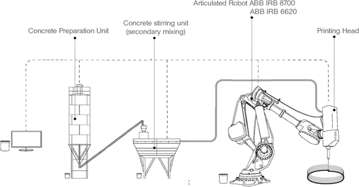
8.2. 3D printing technology and case studies
8.2.1. 3D extrusion–deposition printing
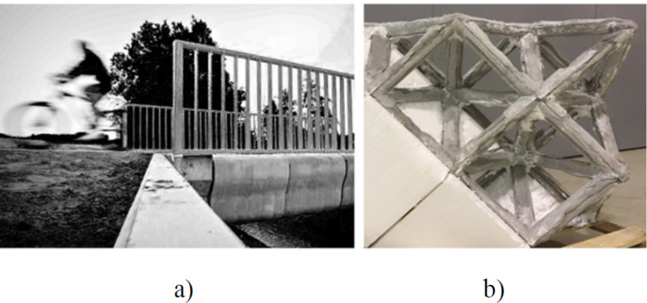
8.2.2. Material-saving construction elements
8.2.3. Case study
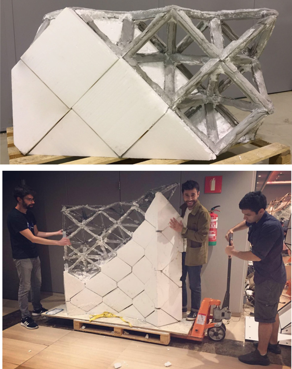
8.2.3.1. Space lattice construction system
8.2.3.2. Design and construction
8.2.3.3. Industrial implementation
Industrial registration
8.2.4. Study issues
8.3. Methodology and case studies
8.3.1. Life cycle assessment method
8.3.1.1. Impact and pollution transfer
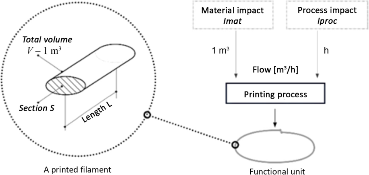
8.3.1.2. Functional unit
8.3.2. Impact model, system boundaries and FU for the 3D concrete printing process


8.3.3. Impact model and FU for the constructive system 3D concrete printing process
Inventory
Parameters
Details/source/references
Concrete
60 kg
(Kuzmenko 2021)
3D printing cell
10 minutes
(Kuzmenko 2021)
Insulation
100 kg
Cement mortar | market for cement mortar | fr
Electricity
0.8 kWh
Market for electricity, medium voltage | fr
Inventory
Parameters
Details/source/EcoInvent references
Concrete
60 kg
(Kuzmenko 2021)
3D printing cell
10 minutes
(Kuzmenko 2021)
Insulation
100 kg
Cement mortar | market for cement mortar | fr
Electricity
0.8 kWh
Market for electricity, medium voltage | fr
Fiber
1.4 kg
Glass fiber production | glass fibre | cut-off | rer
8.4. Results
8.4.1. Environmental impact on the scale of the printed material
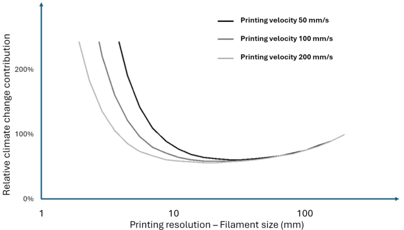
8.4.2. Environmental impact of the building system
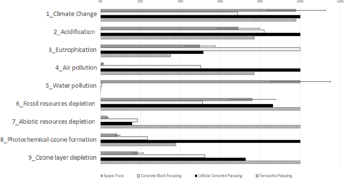
8.4.2.1. Masonry
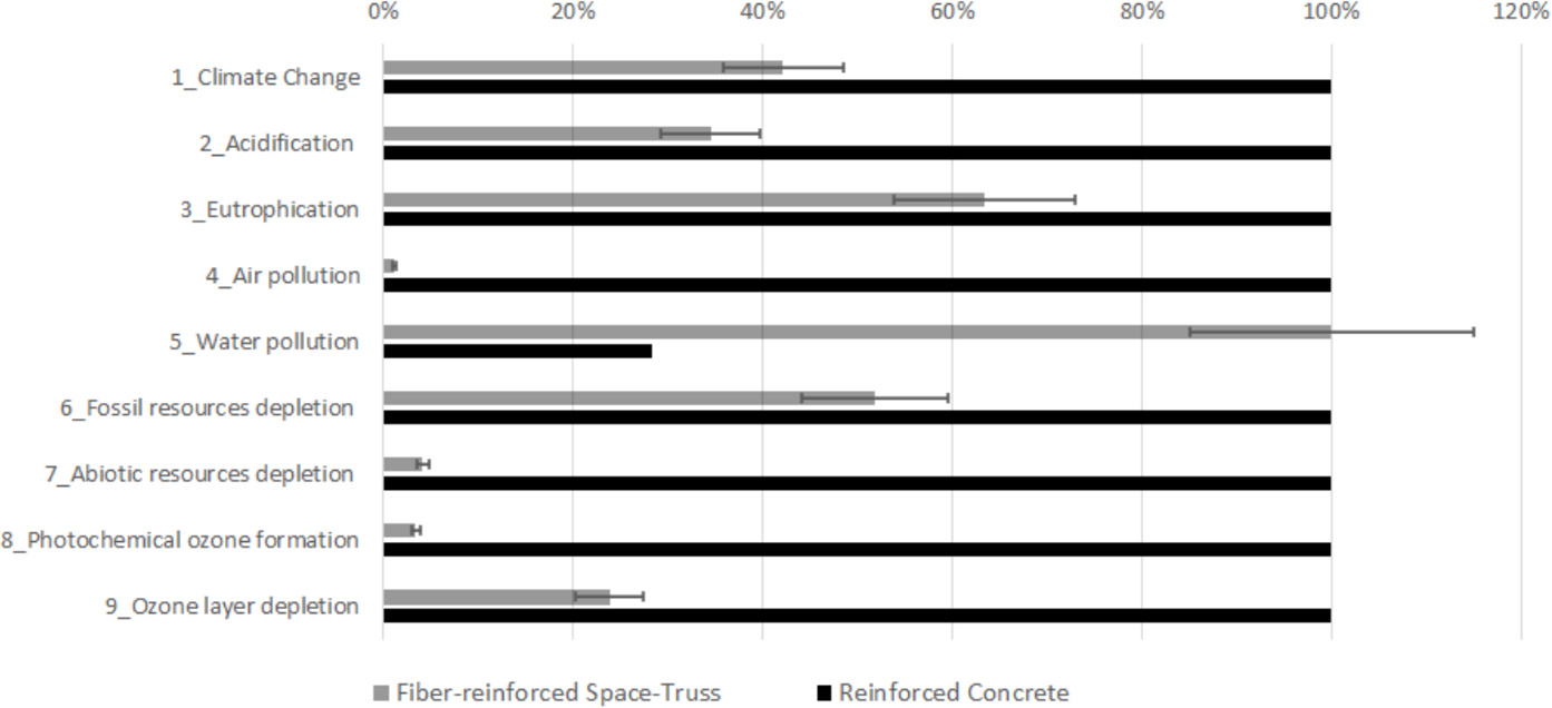
8.4.2.2. Reinforced concrete
8.5. Discussions and prospects
8.5.1. Alternative materials for printing
8.5.2. Impact transfer
8.5.3. Improving the quality and quantity of available inventory data
8.6. Conclusion
8.7. Acknowledgments
8.8. References
Notes
Environmental Impact of 3D Concrete Printing
[8.1]