THE WORLD HEALTH ORGANIZATION suggests external free-field levels of below LAeq (16hrs) 50–55 dB as being suitable to avoid serious disturbance or annoyance during the daytime for dwellings, with more recent European guidelines suggesting maximum external free-field levels outside a dwelling of LAeq (8hours) 40 dB as being suitable to avoid noise disturbance at night. However, in many instances (city center, some urban and suburban areas), a different approach may be suitable.
Table 4.1 defines some of the standard noise criteria applied in a range of cases. External noise is normally considered an issue for residential properties but can be a requirement for outdoor workspaces or education spaces. It should be noted that the requirements can differ greatly from country to country, state to state, and even from county to county.
Advice from the local authority should always be sought when designing for the control of external noise levels, particularly for dwellings.
Noise from entertainment sources (bars, clubs, pubs) is not normally required to be controlled outside the nearest residential property, as in most cases noise from these sources is associated with nighttime use and sleep disturbance within a property. Control levels for such noise will again differ from one area to another, so advice should always be sought, either when building dwellings next to an entertainment source or when introducing a new source of entertainment noise. Good practice guidelines on the design of commercial buildings are given in Chapter 13.
Table 4.1 Suitable external noise levels
Noise source and receiver description | Method of control | Performance criteria Upper noise level at the receptor |
New industrial noise affecting existing residential properties or existing industrial affecting new residential | Noise levels should be controlled in relation to the pre-existing background noise level LA90 dB | –10 dB below the background = positive indication that complaints are unlikely Around +5 dB higher than the background level = moderate likelihood of disturbance +10 dB higher than the back ground level = likelihood of complaint significant |
New office development mechanical noise affecting existing residential properties | Noise levels should be controlled in relation to an absolute level of noise that is frequency-specific | NR35 during the daytime |
Construction noise affecting existing residential and commercial activities | Noise levels should be controlled to a maximum ambient level and operating times on site are restricted | > LAeq 75 dB 8:00 a.m.–6:00 p.m. Monday– Friday 8:00 a.m.–12:00 p.m. Saturday Restricted activity at other times |
Road, Rail,* affecting new residential developments | Noise levels should be controlled for private amenity spaces (e.g., rear gardens, balconies) | >LAeq 55 dB 7:00 a.m.–11:00 p.m. >LAeq 45 dB 11 p.m.–7:00 a.m. |
Airport noise, affecting new residential developments | Noise levels should be controlled for private amenity spaces (e.g., rear gardens, balconies) | >LAeq 57 dB 7:00 a.m.–11:00 p.m. >LAeq 48 dB 11:00 p.m.–7:00 a.m. |
Note:* For rail noise sources, it is also expected that during the nighttime period maximum individual noise events should not regularly exceed LAmax 82 dB.
4.2.1 Introduction
Almost any building that is proposed for an urban/suburban environment should take some account of the control of external noise. The ambient noise requirements set out in Appendix B are specification requirements intended to control this external noise and are an amalgamation of the current best practices issued in North America and Europe. In order to ensure that internal noise levels are achieved, it is necessary to understand the main design techniques used to control external noise. Table 4.2 outlines common noise levels that can be expected in a number of external environments.
4.2.2 Site development and screening
The chances of being able to select a site purely because it will be a quiet location are unlikely, as commercial and amenity requirements will always take precedence. This does not mean that site layouts cannot be developed to avoid additional cost to the building fabric or reduced usability.
When developing a site which is affected by noise, the following approach to design should be adopted:
 For mixed use sites (e.g., residential with commercial), separate residential areas from existing noisy areas. Using office or commercial development to provide a buffer between a major existing source such as a road and any residential buildings can be beneficial.
Table 4.2 Likely external ambient noise levels during the day (adapted from BS8233, 1999)
Source | A-weighted sound pressure level LAeq (dBA) |
Within 32 ft/10 m three-lane roadway (e.g., highway 60–70 mph/95–110 kph) | 70–90 |
Within 32 ft/10 m of a main urban road (30–40 mph/45–65 kph) | 65–75 |
Suburban area screened from main road by intervening buildings | 55–65 |
Parkland within a large town or city | 55–60 |
Secluded country location | 35–45 |

 Use communal space, parking, landscaping areas that are already allowed for in the development as buffer zones to increase the standoff distance between noise-sensitive buildings and a noise source (road, railway, etc.).
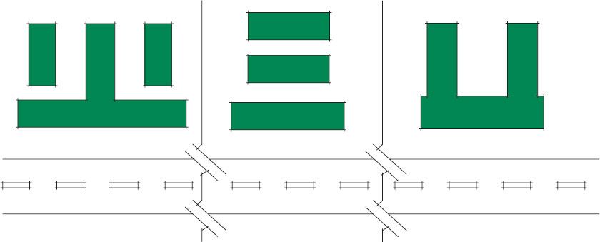
 Figure 4.1 shows the use of either commercial buildings (strip mall) or flats/apartments to provide a barrier block to houses that could be affected by road noise. When the barrier block is flats/apartments, it is possible to allow for higher noise levels outside the building, as it is anticipated that there would be no private amenity space on this façade.
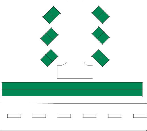
4.1 Barrier block (residential or commercial) used to protect dwellings from noise source (in this instance, a road)

4.2.3 Controlling noise through distance
The use of distance as a means of controlling noise can be effective but only if the size of a site allows for substantial standoff distances. The greater the distance a building is from a noise source then the quieter the level of noise from the source will be within the building. This will depend upon whether the noise source is considered as a point source, such as HVAC equipment, or a line source, such as noise from a railway line or highway. If a house were located 65 ft (20 m) from a railway line or a road, this would be considered a line source and so the level of noise would be reduced by 13 dB relative to the measured noise level at the source. If the house were 65 ft (20 m) from a point source (a lawnmower or AC unit), the level would be reduced by 26 dB.
As a general rule of thumb, the difference between line source and point source attenuation is:
 –3 dB reduction in noise level for each doubling of distance from a line source (road/rail)
 –6 dB reduction in noise level for each doubling of distance from a point source (fixed plant/HVAC).
The following rules of thumb can be applied when considering the development of a site within an urban environment:
 Any development site which is more than 328 ft (100 m) from a major road is unlikely to need control measures for road traffic noise.
 Any development site which is more than 985 ft (300 m) from a major large-scale industrial complex is unlikely to need control measures for industrial noise.
 Any development site which is more than 820 ft (250 m) from a main rail route (heavy freight and/or high-speed passenger) is unlikely to need control measures for rail traffic noise.
Eqs. A.5 and A.6 outline suitable methods for calculating distance attenuation.
4.2.4 Controlling noise with barriers
By including barriers in site designs, it is possible to reduce overall noise levels further. The idea of using a building as a barrier is one possible method, but the most common method would be to construct a fence, bund, or berm.
By breaking the direct line of sight between a noise source and the receiver (a person or a building), we reduce the level of sound because we are increasing the distance the sound has to travel between source and receiver (i.e., the sound has to go over the top of the barrier). A good rule of thumb is to ensure that the barrier is at least 2 ft (0.6 m) above the receiver’s head height (Figure 4.2).
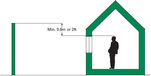
4.2 Minimum height barrier should extend over receiver height to ensure line of sight is broken (assuming comparable ground level between source and site)
Figure 4.3 shows some common barrier arrangements. Barriers work best if they are placed either close to the noise source or close to the noise receiver, rather than centered between both.
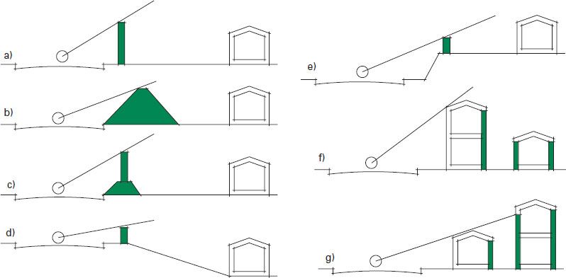
4.3 Barrier arrangements
The circles in Figure 4.3 represent the noise source, with the line of sight possible shown by the straight lines:
a) | A simple barrier that can be constructed from close-boarded timber or a proprietary barrier system. |
b) | A bund or berm formed from earth. Flat-topped berms tend to provide greater levels of reduction, but the required land can be substantial. |
c) | A combined bund and barrier. Useful in providing sufficient height, but reducing the land requirement. |
d) | Dropping the site level below that of the noise source can mean that the required barrier height is reduced. Note: If the barrier is placed next to the noise receiver, it would have to be significantly higher to break the line of sight. |
e) | Increasing the site level can also reduce the required barrier height. Note: If the noise source is in a cutting, a canyon effect can occur where the noise is bounced off the sides of the cutting and can negate the beneficial effects of site level difference. |
f) | The tall building provides screening to the back and the smaller building behind. |
g) | Placing a smaller building in front can, however, be just as effective, as a greater area of the total façades can be protected. The additional distance and the partial screening to the upper front façade of the rear building contribute to the overall reduction of noise. A similar effect can be achieved with podium design buildings. |
The level of attenuation for an acoustic barrier will depend on the following factors.
 The height of the barrier: the higher the barrier, the greater its expected performance.
 The type of noise source: barriers are more effective for stationary noise sources such as HVAC or a road than for a moving source such as tractor that roams around a field.
 The height of the noise source: the higher the source, the higher the barrier will have to be to break the line of site.
 The height of the receiver: the higher the receiver is, the higher the barrier will have to be to break the line of site.
4.4 Using barriers to break horizontal line of sight either by a long barrier or a wraparound barrier
Table 4.3 Basic sound reduction levels from acoustic barriers
Type of barrier | Noise level reduction |
Full barrier (full break in line of sight from source to receiver) | 10 dB |
Partial barrier (partial break in line of sight from source to receiver) | 5 dB |
 The mass of the barrier: generally the minimum surface mass of any acoustic barrier should not be less than 22 lb/ft2 (10 kg/m2).
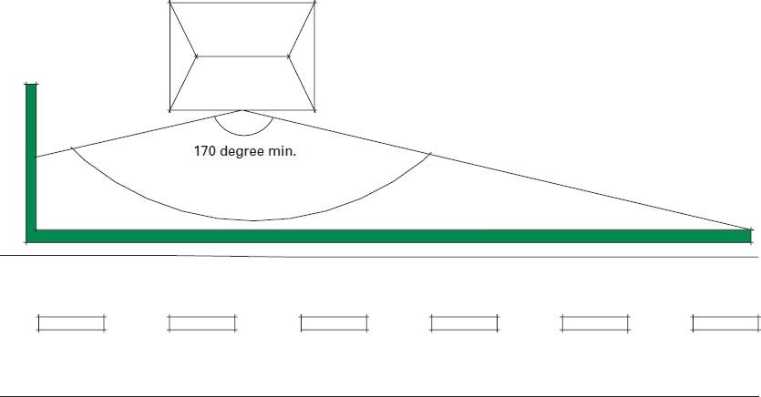
 The barrier must provide a minimum of 170-degree control of view from the receiver position to the source. This can often be more easily achieved by doglegging or bending a barrier around the receiver (see Figure 4.4).
 Openings and gaps in a barrier should be avoided. Total openings, gaps, or cracks should not exceed 1 percent of the surface area (total openings of as little as 4 percent would result in a performance as low as 4 dB).
 Double barriers are often not very effective, as the bulk of any attenuation will be due to the highest barrier.
The calculation of the attenuation offered by an acoustic barrier can be complicated. One possible calculation method is shown in Figure A.1, Eq. A.7. Table 4.3 outlines a good rule of thumb for basic barrier design.
For example, a 6 ft (2 m) barrier is likely to provide 10 dB reduction from road traffic at ground-floor level and 5 dB reduction at first-floor level.
4.2.5 Trees and vegetation
A common misconception is that the use of a strip of trees or shrubs can be used as an effective means of controlling noise. While living noise barriers (solid barriers created from earth and vegetation) can be extremely effective, naturally spread trees and shrubs are not. This is not to say that they cannot be beneficial. By providing a visual screen, they can help to reduce the perception of noise as an issue, particularly if the sound source is mobile. They can also help to provide some masking noise as a result of wind blowing through leaves and branches. When considering these benefits, keep in mind the seasonal variations of the type of vegetation you choose.
4.5 Optimum large building layouts to protect façades from noise, e.g., where road noise is the source (adapted from BRE/CIRIA, 1993)
4.2.6 Optimum building shapes to control external noise
The aim should be to ensure that the maximum number of rooms are screened from a noise source and the positioning of any building does not result in noise reflecting from one façade to another. Figure 4.5 shows the most advantageous layouts for controlling noise to a large area of façade for large-scale developments (e.g., schools, hospitals).
4.2.7 Angle of view to control external noise
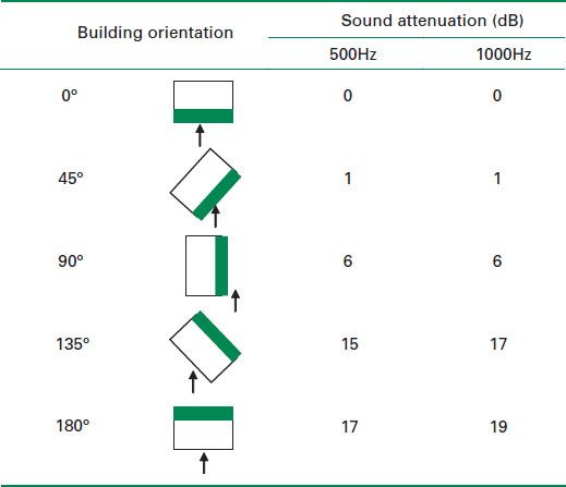
The orientation of a building or a noise sensitive room away from a noise source can also reduce the level of noise disturbance. Where a room directly overlooks a noise source (road, railway line, etc.) the design is entirely dependent upon the distance from the source or the inclusion of an acoustic barrier for attenuation. If the room is angled away from the source then there is an expected reduction in noise due to the angle of view between the receiver and the source. Table 4.4 outlines the expected reductions in sound levels at 500 Hz and 1000 Hz dependent on the angle of view from source to receiver.
Table 4.4 Angle of view correction
4.2.8 Balconies and parapets
The use of balconies and terraces with solid barriers or parapets can be an effective means of reducing noise getting to the building façade. However, it should always be noted that by providing balconies and terraces we create outdoor amenity space that may be exposed to significant levels of noise (see Figure 4.6). Another technique that has been adopted has been to install a false glazed façade detail set out from the front of the actual façade, to provide a translucent screen in front of the windows.
1 Solid parapet wall to front of balcony can help to reduce line of sight between the rooms and an external noise source.
2 Setting overhangs above the façade line can help to further reduce the angle of view to an external noise source, and provides an exposed external soffit that can be lined with an absorptive material to help further reduce noise levels around the balcony/terrace.
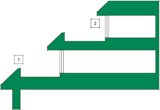
4.6 Protective balconies/terraces
4.2.9 Fin walls and angled glazing
The use of fin walls along balcony or roof terrace areas can help to screen the windows or doors that look out onto these areas. This, along with a reduced angle of view, can help limit overall noise levels within the buildings. Similarly, where the building cannot be oriented away from the source, the location of any glazing can be chosen so that it does not face onto the noise source, or the window can even be oriented so that it does not have the same angle of view as the wall itself (see Figure 4.7).
4.2.10 Single-aspect buildings
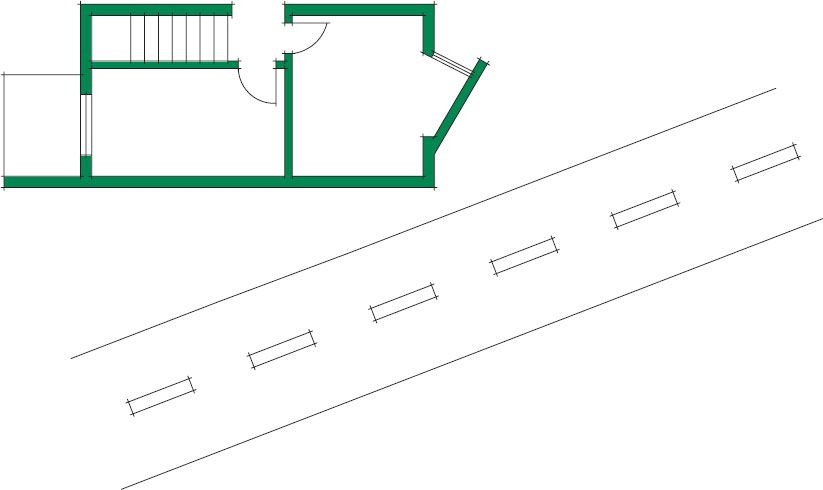
It can be difficult to achieve suitable internal levels, due to the noise exposure experienced on a particular façade. In such instances, the design of single-aspect buildings can be adopted. This is most often a factor in the design of dwellings and means that noise-sensitive rooms such as living rooms and bedrooms are located to the quiet side of a building, while non-sensitive areas such as corridors, bathrooms, and kitchens can be located on the noisy side of a building. Figures 4.8 and 4.9 provide suggested floor plans for a three-story town house and for a two-bedroom flat/apartment where it is necessary to keep noise-sensitive rooms away from the rear façade (e.g., bedrooms and living rooms).
4.2.11 Glazing
The primary method for reducing noise within a building from external sources is through the specification of the building envelope. As external façades are usually composite constructions (wall, glass, and ventilation), it is possible to determine the total attenuation of the system through composite façade calculations (see Eq. A.17). However, it is generally the case that the weakest element in the façade will dictate the overall level of insulation. Allowing for attenuated ventilation usually means that the specification of suitable glazing will dictate acoustic performance. With external walls likely to provide significantly higher levels of acoustic insulation by concentrating on glazing specifications, we can take a cautious approach to façade design and ensure that internal requirements are achieved.
It is commonly accepted that, for some noise sources (commercial noise and industrial noise), internal noise levels within an affected building should be determined in relation to an open window. In many other instances (transportation noise in particular), the assessment of internal noise levels can be determined with closed windows. A wide range of acoustic performance data is published by most glazing manufacturers and will normally detail frequency performance levels along with average or single-figure values.
4.7 Using fin walls and angled glazing to protect rooms from a noise source (e.g., road)
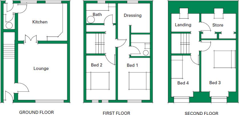
4.8 Three-story house where noise-sensitive rooms are on one façade
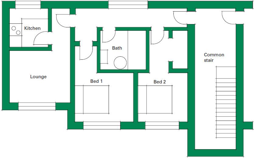
4.9 Flat/apartment where noise-sensitive rooms are on one façade
When selecting a glazing unit, it is best to base any assessment on a performance parameter which rates the window against a low frequency noise source (e.g., RTRA or R’w+Ctr). This is the reduction (R) in noise level provided by the glazing unit when adjusted for a traffic noise spectrum (TRA). Table 4.5 details the expected insulation values for some typical glazing specifications. In addition, it shows expected levels of reduction (Dw) from open windows depending on the source of noise.
As the majority of data provided with regards to glazing performance is based on laboratory testing, it is necessary to consider frame design. The following good practice should be adopted:
 Solid window frames (e.g., timber) tend to provide higher levels of performance over hollow frame systems (e.g., aluminum or uPVC).
Table 4.5 Insulation values for open and closed glazing units (higher values equate to higher levels of insulation) (Waters-Fuller 2005)
Open windows – expected Dw for windows with a free open area of 0.05 m2 | Dw dBA |
Road traffic noise | 12–18 |
Railway noise | 12–18 |
Aircraft noise | 14–19 |
Amplified music | 15–20 |
Closed windows – expected RTRA dB insulation values for typical glazing types | |
Glazing type | RTRA dB |
4 mm float glass / 12 mm cavity / 4 mm float glass | 25 |
6 mm float glass / 12 mm cavity / 6 mm float glass | 26 |
6 mm float glass / 12 mm cavity / 6.4 laminate glass | 27 |
10 mm float glass / 12 mm cavity / 4 mm float glass | 29 |
6 mm float glass / 12 cavity / 7 float glass | 31 |
10 mm float glass / 12 mm cavity / 6 mm float glass | 32 |
6 mm float glass / 12 cavity / 11 mm float glass | 33 |
10 mm float glass / 12 cavity / 6.4 mm laminate glass | 34 |

 Gaps between the window frame and the façade should be packed and sealed prior to fitting of internal and external facings. Gaps which are greater than 25 mm (1 in) should first be packed with a mineral fiber material, then sealed front and back with a flexible sealant.
4.2.12 Roof design
The acoustic design of any roof structure should aim to ensure control from both airborne noise and rain noise.
As a general rule, tile or shingle pitched roofs which have loft space and are insulated using a fibrous material are likely to provide sufficiently high levels of acoustic insulation, so noise from external sources and rain noise are unlikely to be an issue. The only exception to this would be for dwellings which are to be located under an airport flight path.
Similarly, heavy concrete roof structures, ballasted roofs, and green roof systems where vegetation is placed on the roof are expected to provide adequate levels of acoustic control from airborne noise and rain noise for most building types and situations.
While lightweight metal roofs can be perceived as being problematic, it is possible to ensure noise is sufficiently controlled through good design. The following should be considered when selecting a roofing system:
 Multi-layer synthetic roofing membranes (minimum 3/32 in/2 mm) and bituminous roofing membranes can provide good levels of rain noise control even when used on rigid insulation panels. Insulation of the roof structure will be further improved by plasterboard or mineral fiber tile ceiling systems.
 When steel or aluminum roofing systems are detailed, the use of a dampening membrane to the underside of the roofing panel (minimum 3/32 in/2 mm) is recommended to help reduce rain noise.
 Steel or aluminum built-up roofing systems which use mineral fiber insulation materials tend to provide inherently better levels of acoustic control than pre-fabricated composite roof panels which use rigid insulation materials.
 Pre-fabricated composite roofing panels which use rigid insulation can be significantly enhanced with the introduction of a fibrous absorption layer and/or a mass layer to the overall roof systems (e.g., high-density mineral fiber quilt or plasterboard ceilings).
Table 4.6 provides details of some typical roof structures and their expected acoustic performance.
Alterations to ceiling systems can also enhance acoustic performance, for example upgrading from standard ceiling tiles to plasterboard backed tiles can increase insulation levels up to 4–6 dB.
Table 4.6 Insulation values for typical roof constructions
Specification | STC/Rw (dB) |
Traditional roof structure – Tile/slate or shingle on 50 mm battens, 12 mm plywood or timber boards/secondary layer, 160 mm timber rafters fully filled with mineral fiber insulation, vapor check layer, 30 mm timber battens, ×1 layer 15 mm plasterboard | 53–55 |
Concrete roof structure, suspended tile ceiling – Waterproof layer with or without ballast covering over insulation board, 100 mm (nominal) cast in-situ slab, suspended metal frame, min 100 mm cavity lined with mineral fiber ceiling tiles | 52–55 |
Concrete roof structure, plasterboard ceiling – Waterproof layer with or without ballast covering over insulation board, 100 mm (nominal) cast in-situ slab, suspended metal frame, min 100 mm cavity lined with ×1 layer 12.5 mm plasterboard | 55–57 |
Flat timber roof with bituminous lining – Bituminous/asphalt roofing membrane, 12–15 mm ply or timber boarding, 100–120 mm timber roof joists fully filled with mineral fiber insulation, vapor check layer, ×1 layer 12.5 mm plasterboard | 43–46 |
Built-up flat roof system – Metal outer liner (e.g., standing seam roof) on top hat section, mineral fiber insulation layer nominal 200 mm, vapor control layer, 50 mm mineral fiber insulation, profiled steel or aluminum sheet | 33–36 |
Built-up flat roof system with plasterboard ceiling – Metal outer liner (e.g. standing seam roof) on top hat section, mineral fiber insulation layer nominal 200 mm, vapor control layer, 50 mm mineral fiber insulation, profiled steel or aluminum sheet. Metal frame suspended grid system, minimum cavity 150 mm with 12.5 mm plasterboard | 44–46 |
Built-up flat roof system with suspended tile ceiling – Metal outer liner (e.g. standing seam roof) on top hat section, mineral fiber insulation layer nominal 200 mm, vapor control layer, 50 mm mineral fiber insulation, profiled steel or aluminum sheet. Metal frame suspended grid system, minimum cavity 150 mm with mineral fiber ceiling tile | 41–43 |
Pre-fabricated flat roofing panel – 45 mm PU insulated roofing panel on top hat section, 60 mm high-density mineral fiber insulation material within cavity formed by top hat section, 0.7 mm steel liner tray on purlins | 43–46 |
Pre-fabricated flat roofing system with plasterboard ceiling – 45 mm PU insulated roofing panel on top hat section, 60 mm high-density mineral fiber insulation material within cavity formed by top hat section, 0.7 mm steel liner tray on purlins. Metal frame suspended grid system, minimum cavity 150 mm with 12.5 mm plasterboard. | 54–58 |
Pre-fabricated flat roofing system with suspended tile ceiling – 45 mm PU insulated roofing panel on top hat section, 60 mm high-density mineral fiber insulation material within cavity formed by top hat section, 0.7 mm steel liner tray on purlins. Metal frame suspended grid system, minimum cavity 150 mm with suspended tile ceiling | 51–54 |
MECHANICAL SYSTEMS ARE EVER-PRESENT in buildings today in most climates. Human comfort temperatures have been defined slightly differently in different countries; however, most users will adjust their building temperature mechanically if the temperatures are below 50°F or above 100°F (10°C or 38°C respectively). There are a few mechanical systems that are quiet by nature – for example, radiant systems that work by natural convection rather than using fans to promote air circulation – but most mechanical systems produce some degree of noise.
The noisy parts of a mechanical system unit are basically the compressor and the fan. By looking at where these parts are located, mechanical systems can be divided in three categories according to their noise-producing ability.
4.3.1 Fan and compressor in the room
Packaged units or window air-conditioning units have all parts in one enclosure, which is inside the space they are meant to heat/refrigerate. This means that, if you want to adjust your temperature, you need to tolerate the resulting noise. They can vary in noise levels depending on age and fabrication, but there is no such thing as a “quiet” compressor. This type of mechanical system is not recommended for any space where the acoustical environment is important.
4.3.2 Fan in room
Commonly called split systems, they have half of the parts outside the room (the compressor side) and half inside the room (the fan side). The noise is only produced by the fan, and the compressor part is completely separated from the room (outside the building rather than in a mechanical closet with ventilation grills towards the room). This type of equipment can be used in spaces that have somewhat low noise requirements, but not very high acoustical requirements, such as a concert hall or theater, where very low noise levels are sought.
4.3.3 Fan and compressor remote
Central systems are those where all parts of the mechanical equipment are located remotely from the room they intend to heat/refrigerate. The mechanical room is connected to the room by ducts that bring the already-temperature-controlled air. Several conditions should be considered when designing this type of system, to avoid noise traveling through the ducts (Figure 4.10).
1 Allow for use of acoustic louvers for ventilation apertures.
2 Allow additional space around unit for incorporation of acoustic enclosure.
3 Line ceilings with robust absorbent materials to help reducing overall noise levels within mechanical rooms.
4 Isolation of equipment should be allowed for. Isolation efficiencies of 95 percent should be seen as a suitable standard.
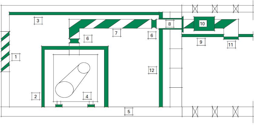
4.10 Central system (remote fan/compressor) mechanical room layout
6 Flexible connectors which isolate duct noise are recommended where a duct connects with a machine, and also just prior to where a duct penetrates through a wall.
7 Lagging of ductwork is recommended (see “Central system checklist” below).
8 Ducts should be lined with a closed cell foam or fibrous sleeve where they penetrate though a wall, to reduce contact with the wall structure. Any gaps at the duct exit should allow for a cover plate (e.g., plasterboard) cut round the duct to seal any gaps.
9 A plasterboard or acoustically insulating ceiling tile should be specified where noise from the duct is anticipated and room noise sensitivity is high.
10 For noise-sensitive rooms, silencers or attenuators may be required prior to the duct termination point.
11 Acoustic grills can be fitted to duct outlets.
Rooftop units Even though rooftop units are technically part of the central system category, they have different acoustic issues of their own. The fact that they could be located right above a space intended to be quiet defeats the purpose. Unwanted vibrations can produce additional noise in the rooms below, and the ceiling partition is the only barrier between the noise source and the room. This type of system is often the culprit for community disputes, due to the fact that the equipment could be well isolated from the building it serves but in direct line of sight with a neighboring building.
Central system checklist
 Ducts distributing air to several spaces should branch out instead of connecting them directly.
 Turbulence noise in turns can be avoided by circular elbows, turning vanes, and silencers.
 Lining inside the duct is more efficient acoustically but can bring poor air-quality conditions. Lining outside ducts is less efficient, but keeps glass fibers far from the air stream. Double duct systems allow for acoustic lining between two walls of the duct.
 Rooftop units should not be located above noise-sensitive spaces. They need to be properly isolated from the structure to avoid vibration transferring to the building, and they need to be properly isolated from other buildings nearby.
 Diffusers and grills that connect the duct to the space will produce more noise at higher air speeds and when halfway closed will reduce air flow.
British Standards Institution (BSI) (1997) Method for rating industrial noise affecting mixed residential and industrial areas. BS4142:1997. London: BSI.
British Standards Institution (BSI) (2009) Noise and vibration control on construction and open sites – Part 1. Code of practice for basic information and procedures for noise and vibration control. BS5228-1:2009. London: BSI.
British Standards Institution (BSI) (1999) Sound insulation and noise reduction for buildings, code of practice. BS8233:1999. London: BSI.
Building Research Establishment & Construction Industry Research and Information Association (BRE/CIRIA) (1993) Sound control for homes. BR238/CIRIA Report 127. London: Crown Copyright.
Jaramillo, A. M., and Ermann, M. G. (2013) The link between HCAV type and student achievement. Unpublished doctoral dissertation, Virginia Polytechnic Institute and State University, Blacksburg, VA.
Mackenzie, R., et al. (2003) A review of acoustic fencing. Edinburgh: Edinburgh Napier University.
Waters-Fuller, T. (2005) The development and production of a guide for noise control from laminate and wooden flooring. London: Defra.