Interaction of sound wave and medium
SOUND INTERACTS WITH MEDIA in many different ways. When a sound wave strikes a wall, there is usually more than one phenomenon occurring to it. This means the energy is distributed in different ways: part of the energy might bounce back (reflection), part of the energy might go through (transmission), and part of the energy yet might be lost inside the material and converted to heat (absorption) (Figure 2.1).
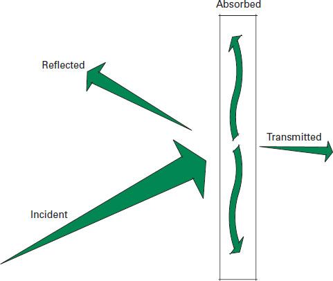
2.1 Incident wave’s energy is being distributed between reflection, transmission, and absorption phenomena
REFLECTION OCCURS WHEN A SOUND WAVE striking an obstacle is redirected back to the space it came from in a specular manner, which is the way mirrors reflect light. The angle of incidence is the same as the angle of reflection (Figure 2.2).
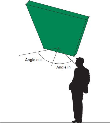
2.2 Angle of sound entering is equal to angle of sound exiting when panel is two to four times the size of the sound wave acting upon it
In order for a wall to reflect sound, it needs to be dense, smooth, flat, and large. If one or more of these characteristics is missing, then there will be other phenomena occurring to the wave. The obstacle in the path of the wave needs to be dense in order to avoid the transmission of energy through it; it needs to be smooth in order to avoid the diffusion of energy in all directions; and it needs to be flat so the energy won’t be either diffused or focalized and it needs to be large in order to avoid diffraction of the wave. This last characteristic is relative to frequency, which means the obstacle should be larger than the wavelength of the frequency it intends to reflect. The best way to understand the relationship between the wavelength and the ability of an obstacle to affect that wave is to imagine sound as water. If you want to stop the flow of a trickle of water you might use your hands. If you want to stop a small stream, maybe you’ll have to use some small trees like a beaver would do. But if you try stopping the flow of the Amazon River with your hands or a small tree, it will just flow around you as if nothing was in its way.
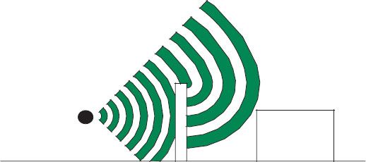
A very specific case of reflection of sound is when a large concave wall or ceiling is made of a reflective material. We know that for a specular reflection of sound the reflecting wall needs to be flat, and that a convex wall will diffuse the sound energy in multiple directions. When sound strikes a concave wall, the opposite occurs: a focal point exists where all reflections of sound are concentrated. In Figure 2.3 a semicircle room was simulated and reflections of sound can be seen arriving at a focal point. In this case, the curved wall is actually simulated as a sequence of straight walls so the focal point is somewhat larger than for a true circular shape.
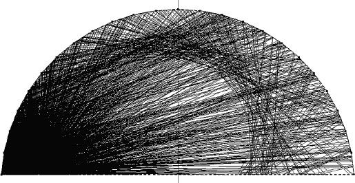
2.3 Focalization of sound reflections due to a concave wall (simulation created using the software EASE)
2.4 Concave ceilings
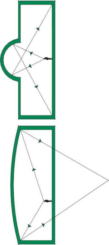
The use of concave walls is not necessarily something that needs to be avoided as long as this phenomenon is taken into account. A very flat curve on a ceiling could be used positioning the focal point outside and far from the listening space (Figure 2.4). The opposite is also true: a very small radius curve can be used if the focal point is not located in the intended audience area.
DIFFRACTION OCCURS WHEN A SOUND WAVE changes direction due to a change of medium, or an obstacle of a similar size to the wavelength. This phenomenon is very important in the design of noise barriers. The noise shadow area created by the barrier would not be the same as the shadow created by light hitting it. Due to the larger wavelength of sound, it will actually bend around the barrier and continue to travel (Figure 2.5).
2.5 Diffraction of noise around a barrier
WHEN A SOUND WAVE STRIKES A WALL that is not smooth or flat, then the incident energy won’t be reflected specularly. This means that the energy will instead be scattered in multiple directions. Scattering can occur on a very specific diffusion pattern if the surface is convex or mathematically designed, or randomly if the surface has a texture in its material or construction (Figure 2.6).
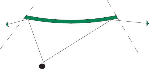
2.6 Sound wave scattered in multiple directions due to a convex surface
SOUND TRANSMISSION THROUGH A STRUCTURE is the passage of the sound pressure wave from the air, into the structure, through the structure and then out the other side. During this process some of the sound pressure is reflected back into the room while some is lost within the structure of the wall (Figure 2.7).
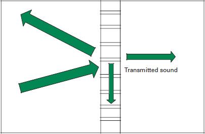
2.7 Basic sound transmission
If a 60 dB sound strikes a wall and 20 dB are measured on the other side of the partition, we say that the wall has 40 dB of transmission loss. This number, as you might have guessed, is different at every frequency. Eq. A.12 details how sound transmission is calculated. Low frequency noise pushes the whole structure causing the sound pressure wave to be transmitted by the surface of the wall or floor. At higher frequencies, sound can also find transmission paths through structural connections or by causing components or sections of the partition to resonate or vibrate. Finally sound will also transmit through small gaps or voids within the structure or through weaker flanking elements such as adjoining walls or service runs.
All of these frequencies are transmitted at the same time, so that a partition or a panel will be vibrating at different frequencies and in different planes. One way to visualize what is happening is to think of the surface of the sea on a stormy day. The swell of the sea, the slow rise and fall, is like the low frequency sound waves with the smaller choppy surface waves and ripples akin to the mid and higher frequency respectively.
2.4.1 Basic mechanisms for controlling sound transmission
There are eight key factors in the reduction of sound through a building structure:
 stiffness
 resonance
 isolation
 mass
mass
 absorption
 critical frequency
 completeness
 flanking transmission.
Stiffness of a structure The stiffness of a partition particularly affects sound transmission at low frequencies. Stiff materials will naturally resist any force against it, such as a sound wave, and the greater the stiffness or rigidity, the better a material will be at reducing the transmission of lower frequency sound.
Cast in-situ concrete decks can provide very high levels of acoustic insulation between floors despite the apparently slim section of concrete slab. The profiles, while adding mass to the structure, also act as stiffeners to the floor structure and so performance levels are better than may be expected from a simple thin slab of a similar thickness (Figure 2.8). Increased dwangs/noggins or strutting/blocking in a timber floor help improve the stiffness of a floor. Similarly timber floors with heavy deafening or pugging also help to improve stiffness in the floor as well as mass.
As the sound wave pushes against the surface of a material, there are frequencies at which it is easier for the sound wave to excite the surface of the material. This is similar to the effect you would get when pushing a child on a swing. There is a “sweet spot” where you no longer have to exert any great amount of energy to keep the swing in motion. The destruction of the Tacoma Narrows Bridge or the Wobbly Millennium Bridge in London are extreme examples of what happens when a structure is excited at its natural or resonance frequency.
With wall and floor structures, the more similarity there is in the structure the easier it is for resonance to occur, e.g., solid homogenous walls. Therefore it can be beneficial to the sound insulation of a structure if symmetry in the construction can be avoided, e.g., lining one side of a brick wall with a metal stud and plasterboard.
Where the benefits of stiffness give way to resonance effects, there is a drop in acoustic performance. This may to occur outside the 100 Hz to 3150 Hz frequency range over which sound insulation is commonly measured; however, it has an effect on the overall performance, as it can effectively lower the starting point at which the structure starts to recover. The closer this occurs to the 100 Hz frequency, the greater the effect it will have on the acoustic performance.
Figure 2.9 shows the expected resonance dip from a double-thick brick wall and a twin-leaf-thick brick wall. In both instances the amount of material used is the same, two layers of brick, but the wall with the cavity has a lower resonance frequency and so the dip occurs at a lower frequency along the X axis. This is as a result of isolation creating a mass-spring-mass effect, where the cavity acts like a spring layer dampening the forced transmission of sound from one leaf to the next. If the two lines were laid on top of each other, they would describe the same path, but because of that lower dip in performance the twin-leaf wall gains improvement across the higher frequency range. We have simply moved the resonance frequency back by introducing the cavity.
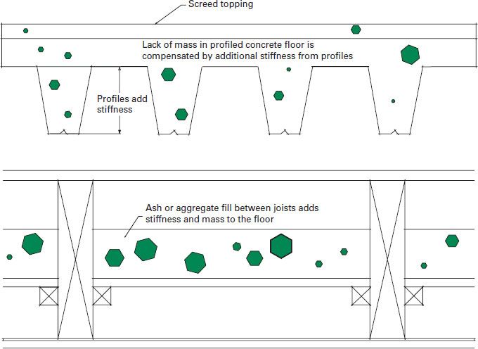
2.8 Profiles in concrete decks or heavy mass materials between joists improve stiffness
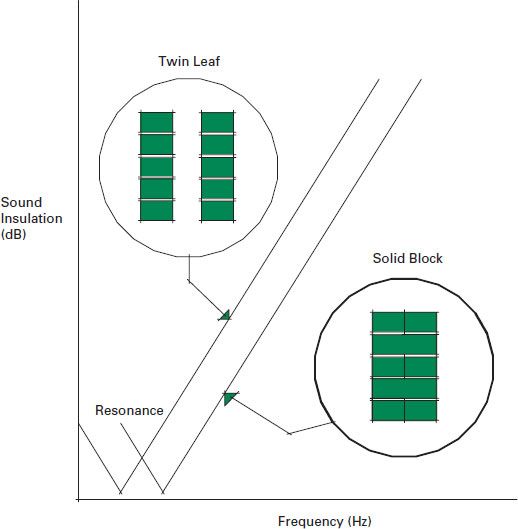
2.9 Resonance dip of two walls with the same mass but different constructions
These constructions also benefit physical isolation, with the thickness and mass of each wall system dictating performance as shown in Eq. A.14.
Isolation of a structure Isolation is the primary means by which twin-leaf partitions, suspended ceiling systems, and floating floors improve the acoustic performance of a wall or floor. Figure 2.10 provides an outline of how the isolation of a solid wall with the application of a free standing partition can improve sound insulation.
Isolation is particularly important for the acoustic insulation of floors against impact sound. Impact resistant mats, isolated floor battens, and floating floor systems all help to isolate a structure from impact sound. They will also have an effect on the transmission of airborne sound, as will twin-stud or twin-leaf wall systems, or independent ceiling or wall lining systems. Finally, the more materials sound has to transmit though, the more energy is lost and so isolation helps with this process by adding different materials and creating cavities in a floor or wall structure.
1 No isolation allows for the lower frequency sound to directly interact with the wall. Here, the natural resonance of a partition is the driving factor.
2 Introducing an isolation layer creates the mass-spring-mass effect.
3 As we move up the frequency range, the wavelength of the sound gets shorter and so, instead of being able to force the whole partition into motion, the sound finds paths through the structure.
4 By separating (or isolating) the different elements of the structure, we break the structural paths that allow for sound transmission at mid- to high frequencies.
(see Figure 2.10)
Mass of a structure The more mass a material or structure has, the more difficulty the sound pressure wave has in forcing it into vibration. For most materials mass is the defining factor in acoustic transmission performance. For every doubling of mass in a structure or material, we should see a 6 dB improvement in acoustic insulation. However, this will only be noticed at the mass-controlled frequencies. This normally occurs at the mid-range of frequencies and can be calculated using the mass law Eq. A.15.
The reason why some single-leaf brick walls can provide similar levels of acoustic insulation to a metal or timber stud partition with multiple linings is the substitution of isolation (e.g., the isolation of the two plasterboard layers by the frame) for increased mass (the inherent mass of the brick or block work).
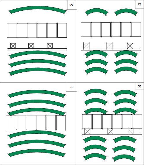
2.10 Isolation
Absorption within a structure Within a structure, absorption occurs (to some extent) within the materials, but also within any cavity. Adding absorptive materials to the cavities within a partition, we can improve the effects of absorption within the cavity by placing a material that is more efficient at absorbing sound than just air. This is normally achieved by adding porous materials such as mineral fiber, glass fiber, open cell foams, or even natural fibrous materials (e.g., sheep’s wool). As a general rule, materials with a density of 0.62–2.25 lb/ft3 (10–36 kg/m3) are best at absorbing sound in a partition cavity. The inclusion of such materials can improve the acoustic insulation of a partition by 3–6 dB. The principles of absorption within a cavity are the same as the principles for absorption within a space and further detail on absorption can be found in Section 2.5.
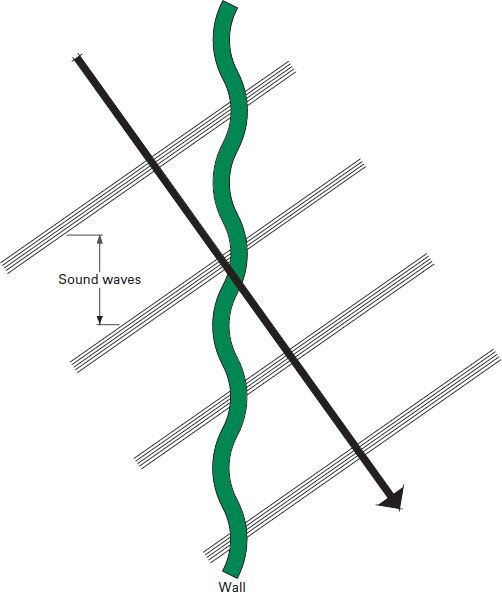
2.11 Critical frequency or the coincidence effect where grazing sound waves coincided with the surface waves on a panel
Critical frequency The critical frequency is also known as the coincidence effect. The coincidence effect occurs when the length of a sound wave grazing against the surface of a material coincides with the natural bending waves on the surface of a panel. Effectively the speed of the sound through the air does not have to slow down when it passes through the material and so the material becomes acoustically transparent, as shown in Figure 2.11.
This is seen as a dip or leveling out in performance at frequencies above the mass controlled region. The thicker a material, the lower the critical frequency becomes and the more likely it will occur within the frequencies of interest for sound insulation. They are normally easy to distinguish in lightweight plasterboard partitions, as they tend to occur at around 2000 Hz, which is around the critical frequency for plasterboard. Using double layers of plasterboard that have differing thickness and mass can help reduce this effect, as can avoiding symmetry in a wall system. The critical frequency can be calculated using Eq. A.16.
Completeness of a structure Without a complete structure, sound can leak through any gaps or holes in the same way that water would leak through the cracks in a dam. In addition to gaps or holes in constructions, incompleteness of a structure or weaknesses in a structure will also have a similar effect. Common reasons for poor sound insulation from incomplete structures are:
 lack of architectural detailing for wall heads or service penetrations
 failing to instruct which contractor is responsible for detailing of wall heads and service penetrations
 missing materials within a wall or floor structure, such as failing to place absorptive layers within cavities or the coring out of screeds and mass elements for services
 poor workmanship.
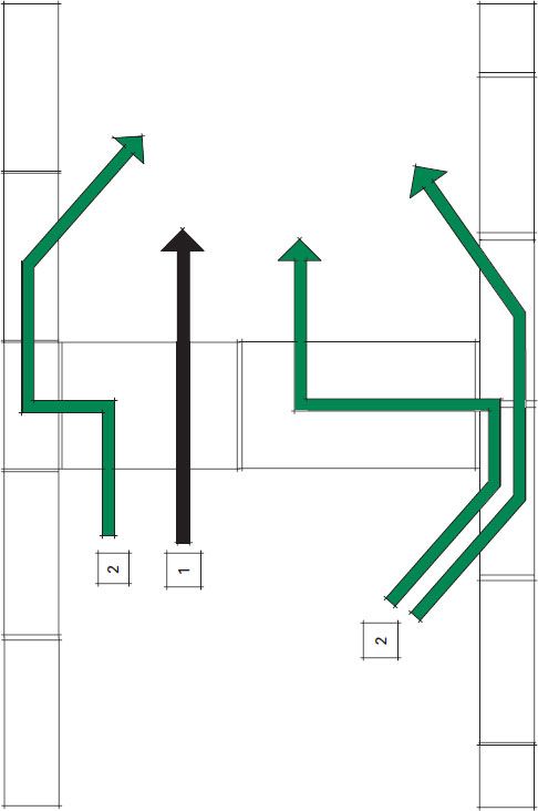
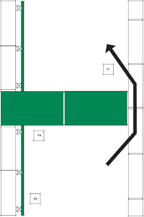
Flanking sound affecting a structure Sound always takes the path of least resistance. Flanking sound transmission relates to noise that is transmitted into an adjoining room or space but which does not come directly through the separating partition. It is possible for there to be at least 12 possible flanking transmission paths between two rooms separated by a simple wall construction (flanking via the side walls, floor, and ceiling). Direct sound is controlled by the wall (Figure 2.12, item 1), while the surrounding structure controls flanking (Figure 2.12, items 2) either directly through flanking structures or even through flanking structures and back into the separating wall.
2 Flanking paths for a simple separating wall.
(see Figure 2.12)
Flanking transmission paths can be controlled by ensuring that the separating wall or floor is built into the flanking walls (e.g., build block work separating walls or pre-cast concrete slabs so they break the flanking wall) or line flanking walls with isolated frames, such as is common in timber kit constructions (Figure 2.13).
1 Untreated flanking wall allows for transmission of sound.
2 Separating wall is built into flanking wall to help reduce the structural transmission path. It can be fully built in or toothed in block work coursings. Fully built, it is more effective.
3 Independent linings either side of the separating wall help to control flanking transmission.
(see Figure 2.13, page 26)
Note: The higher the performance requirement of the partition, the greater level of flanking detail is required.
Flanking transmission can be a particular problem with masonry-supported timber floors where there is a strong structural connection between rooms due to continuous masonry walls running up through a building. It is generally recommended that such constructions are avoided for floors where performance levels of above STC/Rw 55 dB are required.
2.12 Flanking transmission paths
2.13 Methods of controlling flanking sound transmission
2.4.2 The difference between and plasterboard stud partitions
Block work or concrete walls or floors depend on structural mass for good acoustics and tend to provide good insulation at low frequencies. Good performance can also be achieved at high frequencies if the partition is well sealed (e.g., parge coats on block work walls or cast in-situ concrete slabs). These structures tend to have very rigid connections, so isolation for impact sound should always be considered for concrete floors, although soft floor coverings can often provide more than enough control.
Timber separating floors/walls or metal stud partitions depend on isolation of the structural elements for their performance. They tend to have poorer levels of performance at low frequencies and the only way to reduce this effect is to provide larger cavities between linings (i.e., deeper wall and floor sections). They tend to provide good levels of sound insulation at higher frequencies, due to the inherent separation of the flanking structure and the overall completeness of the partition type. With good isolation detailing, timber floor structures can provide good performance against impact sound. The presence of open cavities within the structure should also be seen as an opportunity to introduce acoustically absorptive layers to help further reduce sound transmission.
ALL MATERIALS WILL ABSORB some sound that comes into contact with it. As a sound wave impacts onto a surface, some of the energy is reflected back, some is transmitted through the material, and some is lost within the material itself. The harder, heavier, and smoother a material is, the poorer it will be at absorbing sound. The only exception to this rule comes in the form of panel absorbers. Finishes such as glass or brick are poor at absorbing sound, while finishes such as soft, unvarnished timbers are better and mineral or glass fiber ceiling tiles are very good. Table 2.1 shows some common materials ranked in order of how well they absorb sound.
The Noise Reduction Coefficient (NRC), used in North America, or the average absorption coefficient (άw), used in Europe, define how good a material is at absorbing sound. The closer the material is to 1, the more sound it absorbs.
There are databases available which detail the acoustic absorption of a range of building materials, finishes, and even items of furniture. Appendix C includes two tables showing typical performance values of a range of materials, but it is worth seeking measurement data from manufacturers on a project-by-project basis.
Table 2.1 Acoustic absorption of materials ranked by performance
Material | NRC | Performance |
Marble | 0 | Almost completely reflective |
Plastered block work | 0.05 | Very poor absorption |
Window | 0.15 | Low absorption |
Carpet on rubber underlay | 0.55 | Good absorption |
Mineral fiber ceiling tile with | 0.95 | Almost completely absorptive quilt overlay |
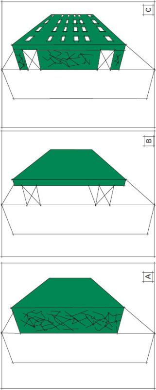
2.5.1 Porous absorbers, panel absorbers, and composite absorbers
Acoustically absorptive materials commonly used in architecture fall into three main categories:
A Porous absorber
B Panel absorber
C Composite absorber
(see Figure 2.14)
Porous absorbers are materials such as mineral fiber ceiling tiles, carpets, curtains or open cell foam panels. Here sound waves come into contact with the material and the energy in the sound wave is transferred into the porous material. The sound wave causes friction within the porous or fibrous structure of the material thereby changing the sound wave energy into heat. Acoustic energy is lost and the sound wave being reflected is weaker. Porous or fibrous absorbers are commonly good at absorbing sound across a wide range of frequencies.
Panel absorbers are made of a thin panel that is set off a wall or ceiling surface and the depth of the cavity behind the panel, along with the overall mass of the panel, determines the frequency at which most sound is absorbed (see Figure A.2 and Eq. A.20). As sound hits the panel, some is transmitted through into the cavity and this sound is then reflected off the wall or ceiling and back toward the panel. The sound wave passing through the panel causes it to vibrate and, by setting the panel a particular distance from the wall, it is possible to have the panel vibrate with the sound wave being reflected off the wall. Two wave fronts which are out of phase but vibrating at the same speed will tend to cause a canceling effect whether they are sound in the air or waves in the sea. Solid panel absorbers are better at controlling reverberation at lower frequencies, although the lower the frequency, the further the panel would have to be set from the wall. They are also more effective around a narrow band of frequencies.
2.14 The three most common absorber types
Resonant absorbers, also called cavity absorbers, work like an empty bottle when you blow a constant column of air at the opening and it produces one tone (see Figure A.3 and Eq. A.21). The only way to change that tone is to change the volume of the cavity by filling it partly with water. Resonant absorbers are then a single or a group of “recipients” that are tuned to absorb a single frequency.
Composite panel/porous absorbers are a mix between the previous categories. A panel absorber is enhanced by introducing an acoustically porous material in the cavity created by the panel and the wall. The panel is usually also given perforations or slots which allow sound waves to be better absorbed by the fill material as well as having a Helmholtz effect (resonance) where the perforations or slots allow for absorption. The greater the number of slots or holes, the better the panel will work at higher frequencies. These composite absorbers can provide good performance across a range of frequencies.
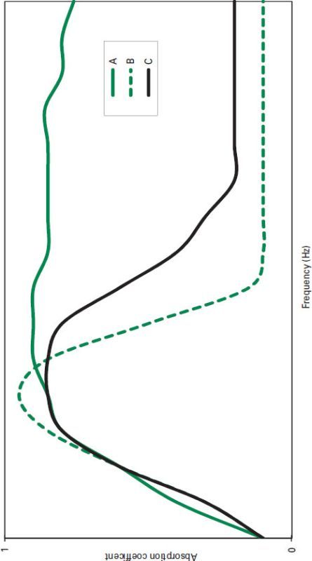
A | Porous absorbers work at a wide range of frequencies. |
B | Panel and resonant absorbers work at a narrow range of frequencies but perform better. |
C | Composite absorbers widen the range of panel or resonant absorbers but lower performance at the design frequency. |
(see Figure 2.15)
2.5.2 Effects of material properties of absorbers
Alterations to the material properties of an acoustic absorber can affect how it will perform.
For porous materials, the following rules can be applied:
 The deeper the panel, the better it will perform at low frequencies and so enhance performance across the frequency range. Some of this performance can be obtained by separating the panel from the wall.
2.15 Acoustic absorbers and their frequency performance
 Densities of between 0.62 and 2.06 lb/ft3 (10 and 33 kg/m3) tend to absorb sound more efficiently.
 Larger panel sizes will be more effective at absorbing low frequency sound.
 For porous materials, achieving effects below 100 Hz is likely to result in impractically thick panels.
For panel absorbers, the following rules can be applied:
 Where thinner panel materials are used, performances at lower frequencies will be improved; thicker panels will be more effective at absorbing higher frequencies.
 Increasing the distance the panel is set from the wall will result in better performance at lower frequencies. Shallower depths will absorb higher frequencies better.
 Increasing dampening of the panel, e.g., laminated materials, will help absorb sound across a wider frequency band.
For composite panel absorbers with porous backings and perforations/slots, the following rules can be applied:
 The rules specific to the properties of the porous material and panel, given in the two preceding sections, will apply.
 Perforations ratios of 15 percent are sufficient for thin panels, but this should be increased if the panel thickness increases (30 percent perforations are common).
 It is better to perforate with many small holes than with a small number of large holes.
2.5.3 Rating acoustic absorbers
Some acoustic absorbers are good across a frequency range, some better at specific frequencies, but all are rated against either the Noise Reduction or Absorption Coefficient. In Europe, categorizations from A (highly absorptive materials) through E (very little absorption) are used (BS EN ISO 11654 1997) and broadly fall into the categories shown in Table 2.2.
Highly absorptive materials such as mineral fiber will have absorption coefficients of around 0.9 (1.0 being around 100 percent absorptive). It is unusual to see materials with absorption coefficients of above 1.0, as this would suggest that they are more than 100 percent absorptive.
Table 2.2 Absorption performance levels (BS EN ISO 11654:1997)
Absorption classification | Panel absorbers | Porous absorbers |
Minimum average άw between 250 Hz and 2 kHz | Minimum performance at each 1/3 Octave Band | |
A | 0.90 to 1.00 | >0.7 @ 250 Hz >0.9 @ 500 Hz to 2 kHz >0.8 @ 4 kHz |
B | 0.80 to 0.85 | >0.6 @ 250 Hz >0.8 @ 500 Hz to 2 kHz >0.7 @4 kHz |
C | 0.60 to 0.75 | >0.4 @ 250 Hz >0.6 @ 500 Hz to 2 kHz >0.5 @4 kHz |
D | 0.30 to 0.55 | >0.1 @ 250 Hz >0.3 @ 500 Hz to 2 kHz >0.2 @4 kHz |
E | 0.25 to 0.15 | >0.0 @ 250 Hz >0.1 @500 Hz to 2 KHz >0.05 @4 kHz |
In North America, it is common to use the Noise Reduction Coefficient (NRC) to rate absorbers, which is a simple average of the absorption coefficient at the mid-frequency octave bands:
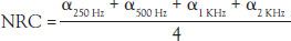
Because this single number does not give a clear idea of the properties of the material at the full frequency range, it is only used commercially. For specific calculations or design decisions, it is recommended to look for specific frequency band absorption coefficients.
2.5.4 Perceived impact of absorption
Adding or reducing the amount of absorption within a room will affect the reverberation or echo within the space, and it is common to alter the specification of particular surfaces or materials. In subsequent chapters, guidelines will be given on recommended surface areas of absorptive materials that should be added to particular types of rooms, to allow for target reverberation times to be achieved.
To achieve significant differences in perception, significant increases in absorption are required, i.e., entire wall, floor, or ceiling finishes may need to be altered.
Controlling reverberation also has an effect on the overall noise level within a room. By increasing the absorption in a space, we can reduce the overall noise level within a room. This can be of value when dealing with noise control in high noise environments such as factories. The reduction in overall noise levels is linked directly to the volume of the space. Figure 2.16 details the expected reductions in overall noise levels within a room due to additional absorption.
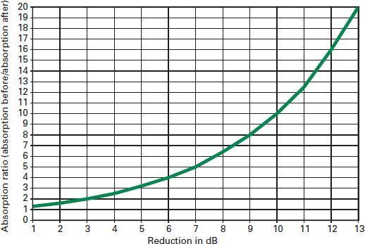
2.16 Noise reduction as a function of increasing absorption
British Standards Institution (BSI) (1997) Acoustics. Sound absorbers for use in buildings. Rating of sound absorption (BS EN ISO 11654:1997). London: BSI.
Brüel & Kjær (1982) Noise control, principles and practice. Nærum, Denmark: Brüel & Kjær.
International Organization for Standards (ISO) (2012) Acoustics – Measurement of room acoustic parameters – Part 3: Open plan offices (EN ISO 3382-3 2012). Geneva, Switzerland: ISO.