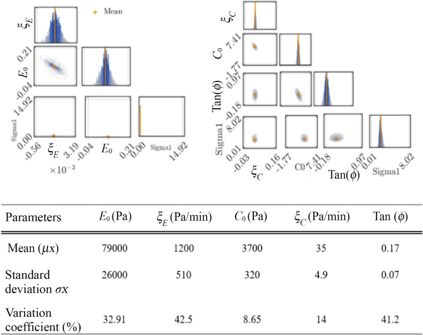
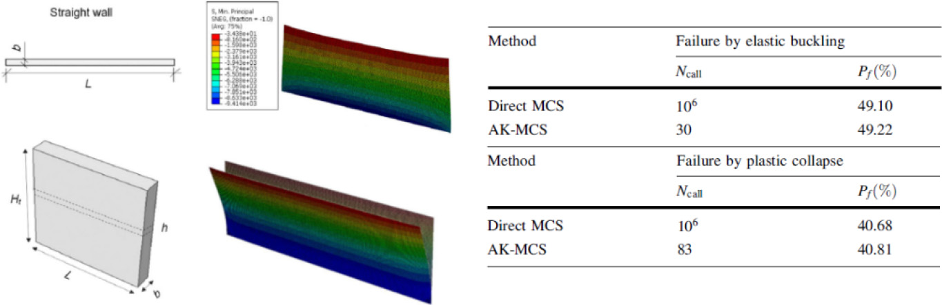
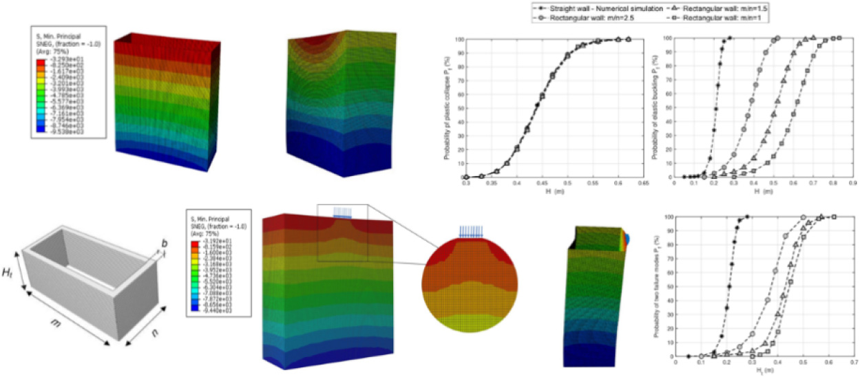
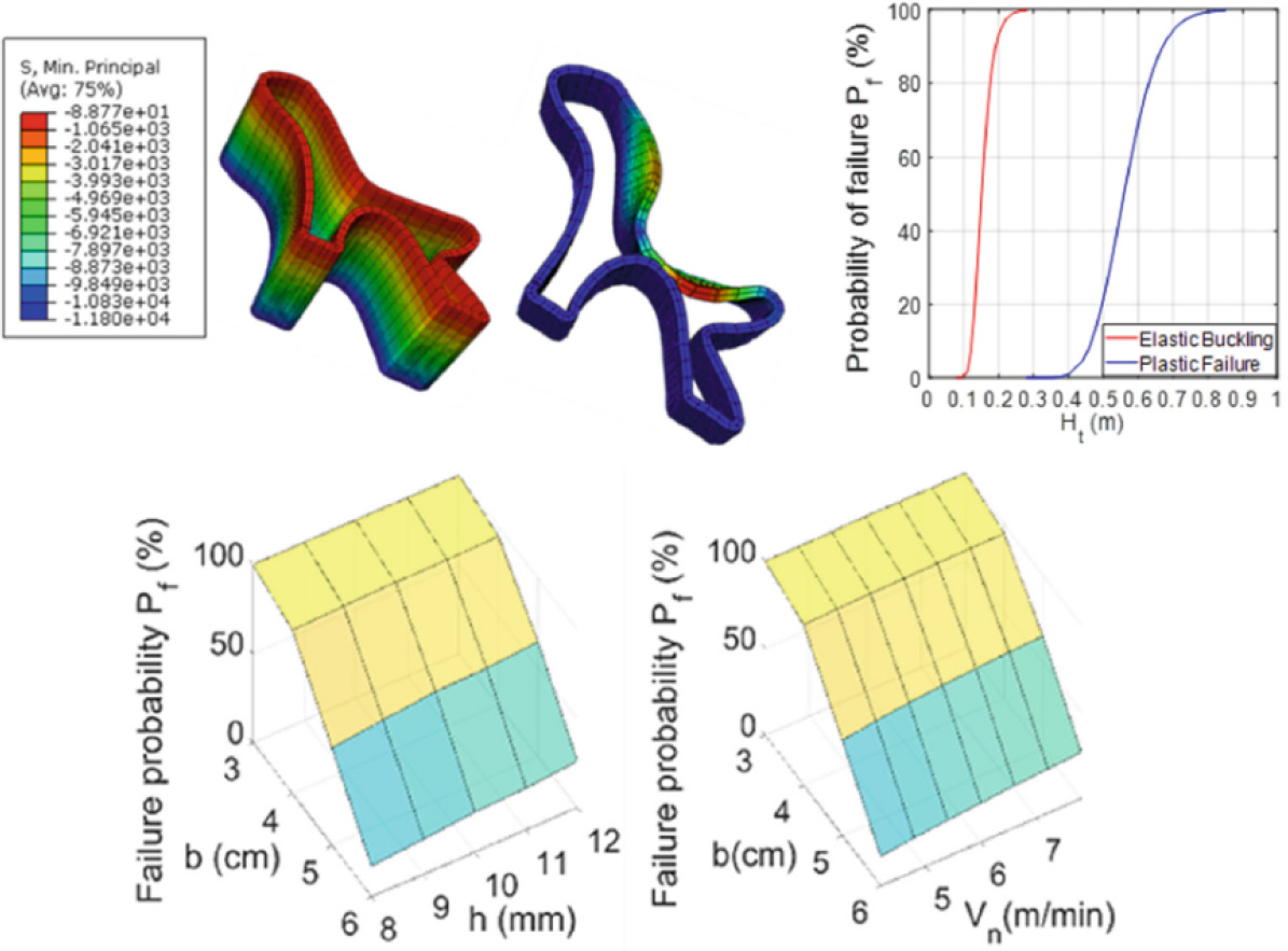
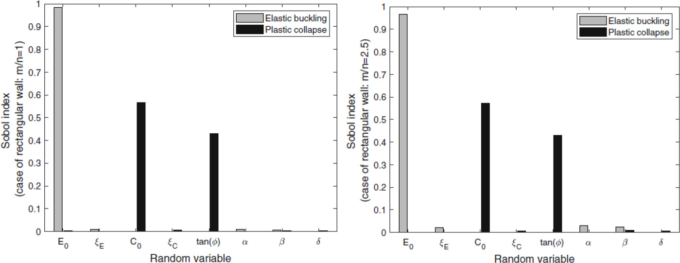
Duc-Phi DO, Zeinab DIAB, Sébastien RÉMOND and Dashnor HOXHA Lamé, Université d’Orléans, France Widely developed over the last two decades, additive manufacturing (AM) through the three-dimensional concrete printing (3DCP) of structural elements represents an important step in the automation process of the construction industry. This innovative technique makes it possible to build structures with a high degree of geometric freedom, saving materials and reducing costs and delivery times, compared with traditional construction methods. In the 3D printing process, the preparation of the geometry of the printed structure, the choice of the material formulation (especially cementitious) and the configuration of the printer with the process parameters are an essential first step before manufacturing. According to this procedure, the digital prototype based on computer-aided design (CAD) of the printed structure is a prerequisite. This virtual geometric model is then transformed into a standard format and cut into layers before being manufactured by the printer. Implementing the programs that control the trajectories and speed of movement of the printer (e.g. the robots) in the digital tools is the primary task in this preparation stage. Due to the novelty of this technique, there is still a lack of knowledge concerning the specific relationships between design, material and process parameters. Indeed, these parameters interact strongly and significantly influence the quality of the manufactured product. The first attempt to find the optimum 3D printing parameters for a given design is based on a trial-and-error approach using a range of print speeds, printed layer dimensions and material composition. However, as soon as the design changes, or new materials become available, this costly procedure has to be restarted, and the print parameters modified as required. Consequently, such an approach limits the development and application of 3D concrete printing on a large scale in practice. If this layer-by-layer manufacturing technique is to be competitive with concrete casting, it must enable a reduction in manufacturing cost and time, without compromising the geometric freedom and structural safety of printed objects. So, alongside the development of geometric modeling and virtual printing simulation tools, it is necessary to integrate 3D printing process modeling into this numerical approach to predict the behavior of deposited layers and structural failure during fresh concrete printing – a phenomenon frequently observed in several trials. In fact, the ability to anticipate the risk of failure of the printed structure thanks to digital modeling in the design phase means that an appropriate layer size and printing speed can be chosen beforehand. During the printing process, these numerical predictions can be updated to enable the right strategy decisions to be made, as well as updating the printing parameters to maximize the success of this innovative construction technique. The main aim of this chapter is to present an overview of the tools, approaches and recent results of numerical modeling in the field of 3D concrete printing. After summarizing digital tools for geometric modeling and virtual printing, we will detail the state of the art in digital modeling of the 3D printing process. This final section focuses on both the structure and the deposited layer. Finally, after a discussion of recent advances and existing limitations, some potential avenues are presented to guide future research in this field. The AM process for concrete structures involves several stages, from the design of the geometric model of a virtual object to the production of the real object and its finishing for commissioning (Abdulhameed et al. 2019). The first step is to design a model using 3D drafting software, respecting the specifications required for the design of the object to be created. Converted into an STL (stereolithography or standard tessellation language) format, this 3D model is then cut into layers and each layer translated into consecutive motion commands using a specific language such as G-Code, which is familiar from CNC (computer numerical control) milling. This code provides the printer with instructions on the path of movement (or tool trajectory) and the corresponding speeds of the printing process. The second step is to configure the machine and prepare the necessary materials before starting production. The final step is to evaluate the printed object in terms of its visual appearance and performance. If quality requirements are not met, adjustments may need to be made to the digital model, machine or materials. Digital tools offer a variety of functionalities that facilitate the design of innovative structures through AM. A parametric approach, for example, has been adopted at Loughborough University, enabling great adaptability of the parameters involved (robot movement speed, printed layer size) in the concrete 3D printing process (Wolfs 2015). This approach has proved capable of identifying the relationships between these parameters automatically using the simulated annealing optimization technique. For this purpose, a script is fully generated in Grasshopper, a graphical algorithm editor, which is a plugin for Rhinoceros (McNeel 2010), including all printing parameters (material properties, geometry and loads). This script is then sent to the calculation software, which is controlled by the Python programming language. Using the script created by Grasshopper, Python controls the execution of both the structural analysis during 3D printing and the algorithm for optimizing printing time and the quantity of concrete used. Various research projects have made use of this methodology, such as the work of Lim et al. (2016), where Grasshopper was successfully used to generate curved layered print trajectories and transfer them to the robotic arm to print the designed model. In the context of the construction sector’s move toward digitalization, the integration of BIM (building information modeling) with 3D printing activities has become a challenge for many research efforts. BIM is an in-depth approach to building construction management that covers all phases of the construction lifecycle, from planning to construction and eventually maintenance (Eastman 2011). It encompasses essential information such as geometric data, resources, equipment, materials and manufacturing data (Wu et al. 2016). Consequently, implementing a BIM-based additive construction procedure can significantly reduce turnaround times. For example, it can facilitate the immediate application of design changes to 3D printing in construction (Ding et al. 2019). In addition, BIM’s ability to store and organize data relating to material delivery, printer control and finishing operations can be used to fully automate the process (Tay et al. 2017; Teizer et al. 2018). An optimized approach that streamlines the use of BIM in the 3D printing process is proposed in Anane et al. (2021). The suggested approach consists of a tightly coupled approach from BIM software realized using the Rhino.Inside.Revit plugin (Vandezande et al. 2012). The print script is developed in Rhinoceros using Grasshopper, since it is much more widely used in the digital manufacturing environment. Consequently, the print simulation and command lines are instantly generated with Rhino.Inside.Revit, that is, Rhino running in Revit’s memory space. The Speckle plugin can be used for collaboration between different stakeholders in a project and will be used to transmit geometric information and exchange print data in real time between the software it supports. The augmented reality representation of 3D printing simulation could be used by Fologram, a real-time connection between mixed reality devices and Rhino and Grasshopper (Fologram for Rhino and Grasshopper n.d.; https://www.food4rhino.com/en/). The result of this process illustrates the simultaneous visualization of the developed 3D print model in four columns from left to right: in Rhinoceros, Revit, Speckle web viewer and in augmented reality, thanks to Fologram. However, this approach still has certain limitations when it comes to mesh transfer, since 3D printing is based on meshes, which are often data intensive. Numerical modeling of the 3D concrete printing process is a complex task, involving the prediction of the behavior of components and/or the entire concrete structure during printing. Indeed, to accurately model the entire printing process, the numerical study must be carried out at two critical levels of the process: the material deposition level at the deposited layer scale and the printed structure level. However, modeling the behavior of fresh concrete during the printing process, whose nature varies from a viscous fluid state (as in the extrusion and material deposition steps) to a solid state after deposition of the printed layers, presents a first obstacle. Furthermore, from a numerical point of view, simulating behavior from the material to the structural scale is very costly and always presents a major challenge for engineers and researchers. Consequently, there is no universal model in the literature to represent the behavior of fresh concrete, and numerical modeling of the 3D printing process is very often carried out separately at each scale. For the purposes of this chapter, we will limit our synthesis to the two scales aimed at predicting structural stability (i.e. buildability) during 3D printing and behavior at the deposited layer scale. It is generally recognized that structural failure during 3D concrete printing is controlled by two mechanisms: instability due to elastic buckling or plastic collapse of the unsupported printed structure (Roussel 2018; Suiker 2018; Wolfs et al. 2018; Kruger et al. 2019; Roussel et al. 2020; Suiker et al. 2020). The progressive increase in load due to the self-weight of successive layers in the absence of formwork and the insufficient development of the strength and stiffness properties of extruded concrete throughout the process are the sources of these failure mechanisms (Reiter et al. 2018). The study of buildability aims to predict the possibility of printing the structure before it fails, and initial attempts have been made on the basis of analytical solutions. These analytical solutions were based on comparing the gradual increase in load due to the addition of printed layers, to a failure stress determined from the shear yield stress of the fresh material considered as a yield stress fluid (Perrot et al. 2016; Wangler et al. 2016). In addition to this plastic failure criterion, Roussel (2018) presented an analytical method for determining the critical height at which elastic buckling is expected to occur for a wall subjected solely to its own weight. The advantage of these analytical solutions lies in their ability to easily determine suitable printing parameters (such as robot travel speed, dimensions of the printed structure), thus providing an initial estimate of structural failure prevention requirements during 3D printing. However, the simplicity of this analytical approach means that the gradient of material properties and variations in process parameters over the height of the object cannot be taken into account. To take specific account of these different parameters, it is necessary to use methods based on numerical modeling. Table 7.1 summarizes the various contributions to numerical modeling of the 3D printing process. The application of numerical modeling to study structural behavior during the 3D printing process was first shown by Wolfs et al. (Reiter et al. 2018). A 3D finite element model was generated for computation by Abaqus software and driven by a custom parametric Python script. This model simulates the successive addition of layers and thus the added gravity load through a nonlinear geometric analysis until completion or failure of the structure. At the interfaces, the surfaces of the layers have been fused together by a geometric bonding constraint, so that there is no relative movement between them. The speed of activation depends on the parameters of the printing process and the length of the object contour. The mechanical properties of the material develop for each layer throughout the analysis as a function of their age in the printing process. In this study, the Mohr–Coulomb (MC)-type plastic failure criterion was adopted and a linear time-dependent evolution of mechanical properties (such as Young’s modulus and cohesion) of fresh concrete was suggested. These required material properties were obtained from an experimental set-up comprising a direct shear test and a uniaxial compression test. The numerical predictions of Wolfs et al. (2018) were verified by comparison with experimental results. This model enables structural behavior during 3D printing to be studied systematically, taking into account two failure modes, namely, elastic buckling and plastic collapse. However, from a quantitative point of view, the model overestimated the prediction of the maximum number of printed layers before failure by 58.6%, compared with the experimental results. This difference was explained by the overestimation of material properties determined from testing due to sample compaction, or by neglecting the influence of geometric imperfections in the printed structure. Furthermore, this analysis only gives indications of the object’s structural behavior such as the maximum number of printable layers, but no suggestions on how to improve the geometry or determine the best printing parameters that can be provided. In another study by Wolfs et al. (2019b), geometric imperfections are considered for numerical predictions of structural failures. Indeed, the first buckling mode profile obtained by bifurcation analysis is taken to model the initial imperfection whose amplitude is equal to 0.1% of the deposited layer width. Through analysis of the elasto-plastic behavior of the printed structure, the failure height is defined as that at which the out-of-plane displacement of the structure exceeds half the width of the printed layer. Different walls of the same 60 mm width but varying lengths (L = 1 m, 5 m or 10.4 m) were printed to failure for experimental verification of the numerical model, whose input parameters for the mechanical properties of the concrete were determined by the results of triaxial compression tests. The comparison shows an underestimation of the numerical model of around 15% of the critical height before failure for a 5 m long wall, and the discrepancy can reach 43% for a longer wall (L = 10.4 m). The discrepancy between numerical predictions and printing experiments was explained by the method used to characterize the properties of the printed material, which ignored the presence of confining pressure in the lower regions of large structures, as well as the effect of temperature on material properties. These studies encourage the advancement of numerical modeling of 3D printing in order to increase the accuracy of predictions and take into account thermal and humidity factors due to their significant impact on early-age strength and stiffness properties, and thus on print failures (Wolfs et al. 2019b). These developments could enable numerical assessment of the strength of adhesion between successive layers, which has been shown to be highly dependent on process parameters and environmental conditions (Le et al. 2012; Keita et al. 2019; Nerella et al. 2019; Wolfs and Suiker 2019; Wolfs et al. 2019a). In addition, it could serve as a starting point for extending the simulation to the hardened state. Table 7.1. Digital models of the 3D printing process at structural scale While initial studies have demonstrated the ability of numerical modeling to describe the 3D concrete printing process, a great deal of work has been carried out to improve the accuracy of predictions. For example, to simplify mesh creation for complex structures, various authors (Ooms et al. 2021; Vantyghem et al. 2021) propose the technique of automation using data transferred from CAD software in the geometric design phase to finite element analysis software. This approach removes all manual pre-processing steps from the digital modeling of the 3D printing process. Under this approach, the geometric model of the structure is imported and discretized automatically using the Grasshopper programming language, regardless of the complexity of the geometry to be printed. The file created contains all the information required (mesh, materials, boundary conditions, interactions and calculation steps) for numerical modeling in FE software (e.g. SIMULIA Abaqus/CAE). Technically, the discretization of the geometric model of the printed structure can be achieved in different ways. In the work by Vantyghem et al. (2021), the authors present a method called VoxelPrint, which involves voxelizing the geometric model into a set of 3D unit cubes (i.e. voxels). This technique uses the same process as for rasterizing a vector graphic into a raster image (a series of pixels). The main idea behind the voxelization algorithm is that a 3D space around the model is filled with many discrete cubes, and if the center of that cube lies within a predefined area of the 3D model and print path, the cube is considered to belong to the printed geometry. In this way, any 3D shape, no matter how complex, can be voxelized, and FE mesh generation is straightforward. One advantage of VoxelPrint is that a single large voxelized model is created (a single piece in the FE software), where interactions, binding constraints or contact properties are not specifically defined. The disadvantage of this method is that it does not allow the use of advanced contact properties, for example, to model joints, that is, weakened behavior between layers. In the calculation input file, mesh elements (voxels) are first deactivated in the initial step, using the model change function, and then progressively reactivated in each subsequent analysis step. This voxel-based simulation approach has been validated by comparison with the results of Wolfs et al. (2019b) in the case of a cylinder, where it provides a similar prediction of the maximum print height, after which the structure collapses (Vantyghem et al. 2021). The applicability of VoxelPrint was also demonstrated in Vantyghem et al. (2021) by its ability to distinguish failure by elastic buckling from failure by plastic deformation. Another technique called CobraPrint allows the mesh to be generated by Grasshopper, first dividing the print path into multiple segments, and then assigning multiple mesh elements to each segment. As in the previous method, the segments are activated sequentially along the print path to simulate the printing process (Wolfs et al. 2018, 2019b; Ooms et al. 2021). In addition, the Coulomb friction model is used to present the tangential interaction between layers and between segments of each layer. Comparing with existing studies (straight wall (Wolfs et al. 2019b) and cylinder (Wolfs et al. 2018)), this technique showed an improvement in the prediction of fracture height without the need to incorporate initial geometric imperfections. In order to simulate the whole 3D printing process by following the real printing path of complex structures, Nguyen-Van et al. (2021) proposed a new modeling procedure (virtual printing procedure). The principle of this procedure is to integrate the G-code files of the toolpath patterns into the simulation process. This procedure makes it possible to simulate the failure modes of structures during 3D printing, whatever their complexity. Examples include bio-inspired cellular blocks containing continuous non-self-intersecting surfaces, known as the triply periodic minimum surface (TPMS), gyroids and primitive blocks. The developed model was validated by comparison with experimental results on a printed hollow cylinder (Panda et al. 2019). The ability to predict both failure modes as well as the deformed shape of the layers was demonstrated. Not taking into account the effect of geometrical imperfections explains a moderate overestimation of 4.3% of the numerical prediction of the fracture height, compared to the experimental value. At present, to model the plastic collapse of the concrete structure during 3D printing, the M-C perfect elasto-plastic model is widely adopted (Wolfs et al. 2018, 2019b). However, in a recent contribution, Liu et al. (2022) chose another model, the Drucker–Prager (D-P) model, to simulate the buildability of the printed structure according to the deformation failure mode. According to these authors, the D-P model provides a better representation of the stress–strain relationship, particularly in the post-peak phase, by using the strain-hardening function calibrated from the uniaxial stress-strain curve of early-age concrete. More specifically, using the same printed structures (e.g. the hollow cylinder (Wolfs et al. 2018) or the straight wall), replacing the M-C perfect elasto-plastic model with the D-P model shows an improvement, with the difference between numerical predictions and experimental results dropping from 58.6% to 44.8% in the cylinder case (Wolfs et al. 2018). In the case where elastic buckling is the dominant failure mode (straight wall case), the predicted results with the D-P and M-C models are identical as expected. In parallel with finite element methods, Chang et al. (2020) have used the lattice model for numerical analysis of the 3D printing process. This method, based on a 3D network of Timoshenko beams, makes it possible to take into account the heterogeneous characteristics of printed objects and the influence of non-uniform gravitational loading. In this numerical model, structural failure according to the strain failure mode occurs when the lateral displacement exceeds the width of an individual layer, while material failure or plastic collapse results from the accumulation of local damage in the lower layers (Chang et al. 2021, 2022). The model correctly reproduced both failure modes, and the predicted critical print height improves on existing models in the literature (Wolfs et al. 2018, 2019b; Suiker et al. 2020). Comparing with experimental data in the cylinder case (Wolfs et al. 2018), the lattice model prediction overestimates the critical print height by 41.4%, which is lower than the 58.6% overestimation by the FE model of Wolfs et al. (2018). For the case of the square wall (Suiker et al. 2020), the relative difference between the two models is of the order of 10%. In the case where the structure fails by elastic buckling, as in the straight wall case (Wolfs et al. 2019b), the critical height predicted by the lattice model is around 12% lower than the experimental data. This lattice model has also demonstrated its ability to model unconfined uni-axial compression tests to calibrate the stiffness and strength of beam elements as a function of time. The material deposition phase is critical and requires high precision to ensure that the final product meets the design specifications and that the printed layers conform to the desired geometry. In the 3D concrete extrusion printing process, deposition strategies fall between two asymptotic regimes at the nozzle (Roussel 2018). In the first case, known as infinite brick extrusion, the extruded material is rigid and has a high initial yield strength, enabling it to resist gravity stresses and stresses due to pumping pressure. The material is therefore not sheared during extrusion, so that the filament cross-section is dictated by the shape of the nozzle. In the second case, known as “free-flow deposition”, the material is sheared by a local contraction or screw mixer before it exits the nozzle. In this case, the final layer geometry results from a competition between gravity and the material’s stress limit. It should be noted that in some cases, where the distance between the nozzle and the previous layer is less than the nozzle opening, the filament is shaped by being pressed between the nozzle and the substrate, until the filament thickness is equal to the distance between two successive nozzle passes. This strategy enables the layer thickness to be controlled, but it can generate local pressure on the lower layers, leading to further deformation of the layer and thus threatening the overall stability of the printed object. Depending on the extrusion process chosen and the properties of the material, the final cross-section of a printed layer can take different forms, the exact prediction of which is a major issue for concrete 3D printing technology. The majority of concrete printers operate using cutting software, which assumes that the extruded filament will conform to a cross-section theoretically determined by applying mass conservation principles and using a filament thickness equal to the gap between the nozzle and the substrate. In reality, there is always a slight difference between this theoretical thickness and the actual thickness, which can accumulate over several layers and can subsequently lead to a significant change in the cross-sectional profile of the printed filaments. These deviations influence the aesthetic quality of the final product and can also lead to geometric non-conformities that can impact the structural properties (adhesion strength and durability) of the resulting printed product; and, in the worst case, to printing failures. In addition, depending on the kinematic process parameters chosen, the filament is susceptible to tearing, cracking or bending in the direction of deposition. The expected, well-controlled cross-section of the extruded filament is achieved when printing is carried out at nominal speed (i.e. when the material flow is equal to the product of the robot speed and the expected filament cross-section) (Perrot et al. 2021; Wolfs et al. 2021). However, in 3D printing installations, material flow at the nozzle is generally less precisely controlled than other process parameters, such as robot trajectory or speed. Starting from the obvious importance of filament shape control and prediction, numerical studies of additive concrete manufacturing at the filament scale have been widely presented in a number of works. The so-called finite volume method (MVF), based on the computational fluid dynamics approach (CFD) is used in Comminal et al. (2019, 2020a, 2020b) to simulate concrete extrusion. In their study, Comminal et al. (2020b) analyze the effect of nozzle position height and the ratio between printing speed V and extrusion speed U on the geometry of the layer printed on a flat surface for a cement-based mortar mix. The simulations are based on two formulations of the constitutive law, the generalized Newtonian model and the fluid elasto-viscoplastic model. These virtual printing simulations provide numerical values of velocity, concrete stress and pressure at the nozzle outlet, as well as a visual representation of the cross-section of the printed layers. The study revealed an increase in pressure under the nozzle as the height separating the nozzle from the previously deposited layer decreased. Previously, the effect of different constitutive laws, covering the wide range of material behaviors, including shear thinning and viscoplastic material phenomena, on a single printed layer was analyzed by Comminal et al. (2019). The printing process is simulated by moving a nozzle horizontally. The cross-section of printed filaments obtained with three different models of non-Newtonian fluids (power law, Herschel–Buckley and Bingham) appears thicker and less wide compared to a reference Newtonian fluid with constant viscosity, which itself produces filaments with a thickness less than the theoretical cross-section generally used by slicing software. To further validate the CFD model developed, Spangenberg et al. (2021) carried out a numerical simulation of up to three layers using an elasto-viscoplastic constitutive law. The model was validated by experimental data on 3D-printed walls, with high accuracy. The study also quantifies the extrusion load imposed on the layer, which was found to exceed the material’s yield strength in some regions of previously printed layers, leading to layer deformation/flow. The model could be used to optimize printing parameters, but the difficulty lies in its high computation time (several days are needed to run a simulation). In Reinold et al. (2019), a numerical model based on the particle finite element method (PFEM) is used to simulate 3D concrete printing. The PFEM is an updated mesh-based approach in a Lagrangian framework. The flow behavior of freshly extruded concrete is based on a regularized viscoplastic Bingham model (Papanastasiou 1987). Its behavior in the elastic regime prior to failure can be modeled by this Bingham model using a large viscosity value. 2D numerical analyses with different process parameters and material properties were carried out to control layer deformations and enable targeted design with an understanding of the forces developing in the vicinity of the nozzle. These analyses reveal that nozzle height in relation to print speed and extrusion rate are the process parameters that govern the tension/extrusion forces under the nozzle. Variation in nozzle width did not result in any significant changes in maximum force values. However, higher stress concentrations were observed for smaller extrusion nozzle widths. The pressure generated under the extrusion nozzle during extrusion appears to be six times greater than that induced by a layer’s own weight. Dynamic interactions during the printing of a second layer on an existing layer were analyzed on the basis of the quantity of material extruded. These were used to optimize the printing process parameters so as to prevent the formation of plastic deformations in the base layer. Thus, this type of multi-layer printing simulation can provide highly detailed information not only on the cross-sectional shape of the layers for predicting buildability, but also for quantifying the quality of surface roughness and providing a basis for predicting inter-layer adhesion. In a recent study (Wolfs et al. 2021), 2D and 3D CFD simulations were carried out, using the finite volume method (MVF) to study the influence of the various parameters of the 3D printing process by extruding infinite bricks. These parameters include the printing speed V, the extrusion speed U, the geometric characteristics of the filament and nozzle (nozzle width and height between two layers) and the elasto-viscoplastic properties of the material. They showed that, when the process is run at nominal speed (V = U), the filament is extruded correctly and appears to be independent of the studied range of material properties and nozzle characteristics. When the extrusion speed is higher than the nozzle speed, U > V, the filament is observed to exhibit periodic elastic instabilities both in geometry (flexion behavior, referred to as filament buckling in Wolfs et al. (2021)) and stress distribution throughout extrusion. An increase in nozzle position height, a reduction in nozzle width or an increase in material consistency (i.e. greater stiffness, yield strength or viscosity) had a profound effect on the flexion of the filament. On the contrary, an extrusion speed lower than the nozzle speed, U < V, causes tensile stresses which can lead to cracking or even tearing of the filament. Similarly, an increase in material stiffness or a reduction in the material’s critical strain increased the occurrence of tears. Analytical expressions for the tear factor and buckling factor were presented to indicate transitions from well-controlled nominal extrusion to filament tearing and buckling. The growing involvement of the academic and industrial sectors in the field of 3D concrete printing is gradually addressing the specific technical challenges associated with this innovative construction process. As previously presented, the numerical modeling tools developed have made it possible to detect and predict various failure modes throughout the printing process, whether they occur at the scale of a printed layer or of the entire structure. Numerical modeling has proved to be a valuable option for optimizing the 3D printing process, as it enables a systematic assessment of the influence of the entire range of materials, geometric parameters and process parameters. Accurate prediction of structural behavior during printing relies on understanding each parameter involved in printing, such as material behavior and properties, geometric features and the printing environment. For example, the numerical study of the buckling of a 3D-printed structure by Wolfs et al. (2018), considering the time-dependent MC elasto-plastic behavior of the material, overestimated the printed heights before failure. The authors explain that compacting the material prior to the experimental tests (unconfined compression and direct shear tests) can lead to an overestimation of the material properties, which in turn can lead to an overestimation of the height before failure and an underestimation of the lateral deformations. Furthermore, in Wolfs and Suiker (2019), numerical predictions lose accuracy due to the influence of thermal heating of the 3D printer during the long printing process, which has not yet been incorporated into experimental characterization or numerical analyses. Deviations between predictions and print tests can also be explained by various sources of uncertainty, such as uncertainties in material property measurements, imperfections or spatial variation in the geometry (e.g. width, thickness and position) of deposited layers, which are neglected in predictions. According to the results of experimental tests (such as the uni-axial compression test and the direct shear test) carried out by Wolfs et al. (2018), a non-negligible dispersion in the shear strength and Young’s modulus of concrete at young age was noted, where a coefficient of variation (COV) of around 20% was indicated for each parameter. This uncertainty is linked to the heterogeneous nature of mortars and the transition state from fresh concrete (viscous fluid) to solid state, which is extremely difficult to accurately characterize. In addition to the uncertainty in material properties, Suiker et al. (2020) have also shown that the eccentricity of printed layers can significantly affect elastic buckling failure during printing. Until now, the analysis of the behavior of the printed structure has been based on a deterministic problem using mean values of fresh concrete properties calibrated from laboratory tests. Variations (or uncertainties) in these properties are neglected, while a perfect rectangular cross-section of the layer is considered, ignoring the geometric imperfections that occur during deposition. Furthermore, in most cases, numerical tools are used to predict the behavior and especially the heights before failure of the printed structure, but they are not yet exploited for their capabilities and potentials, particularly in optimizing the 3D concrete printing process. The first attempt to take into account the uncertainty of fresh concrete properties in buildability analyses and 3D printing process design optimization can be found in Kruger et al. (2020). In this contribution, the authors used the probabilistic approach such as the first-order reliability method (FORM) to assess the impact of the large variation in material properties ignored by the classical deterministic design model. The optimal solution for layer thickness and printing speed was determined in order to minimize printing time. However, this latest study only considers the plastic failure mode, and the elastic buckling phenomenon is not addressed. In this context, Diab’s thesis (Diab 2023) was carried out within the Lamé laboratory, as part of the European Interreg CIRMAP project (CIrcular economy via customizable furniture with Recycled Materials for public Places). In this research work, a comprehensive reliability analysis procedure was developed with the aim of enhancing the predictive capability of numerical simulations and increasing their applicability in optimizing the 3D concrete printing process (Diab et al. 2023, p. 202). More specifically, the analyses carried out by stochastic modeling make it possible to estimate the probability of different failure modes of concrete structures during the printing process, taking into account various uncertainties, such as those of the mechanical properties of fresh concrete. In the proposed procedure, uncertainties must first be quantified. For example, in the contribution by these present authors (Diab et al. 2022), the probabilistic inversion technique based on Bayesian theorem was adopted to quantify uncertainties in the elasto-plastic behavior of fresh concrete. Based on the uniaxial compression and shear test results of Wolfs et al. (2018, p. 20), Bayesian inference is used to determine the a posteriori statistical distribution of five parameters that characterize the structure’s two failure modes during printing (i.e. plastic failure and elastic buckling), as illustrated in Figure 7.1. The results of the uncertainty quantification step are then used as input data for stochastic modeling of the printed structures. While the Monte Carlo simulation (MCS) approach is widely known as the benchmark for reliability analysis, it nevertheless requires a very large number of direct evaluations of the structure’s response, which is numerically very costly. To reduce the considerable time required for these stochastic analyses, the MCS can be combined with a model reduction technique developed on the basis of machine learning. Recently, in contributions by the present authors (Diab et al. 2022, 2023), the combination of the Kriging meta-modeling technique with MCS has been adapted to the field of 3D concrete printing. The main idea of this technique, named AK-MCS, is to iteratively build the response surface of the structure on a very reasonable number of samples of random parameters (i.e. the five mechanical property parameters of fresh concrete). In each iteration, the estimation of the probability of failure of the structure by the MCS can be easily achieved by interpolating the results of the constructed metamodel. After each iteration, a new, more appropriate sample of random parameters is added to reconstruct the metamodel. This AK-MCS stochastic modeling procedure continues until the estimated probability converges. As an example, Figure 7.1 shows the results of deterministic modeling and stochastic analysis of a straight concrete wall during printing. The availability of the analytical solution in this case of a simple structure (Suiker 2018) validates, on the one hand, the results of deterministic modeling by FE and, on the other hand, the applicability of the MCS performed on a million samples verifies the effectiveness of the AK-MCS. The same results for the estimated probabilities of two failure modes (i.e. plastic failure, elastic buckling) were obtained by both methods, but stochastic modeling by AK-MCS requires fewer than a hundred direct assessments of the printed structure. Figure 7.1. Quantifying uncertainty in the elasto-plastic properties of fresh concrete using Bayesian inference (Diab et al. 2022). Figure 7.2. Result of deterministic and reliability analyses of two failure modes (plastic failure, elastic buckling) of a straight wall during 3D printing and comparison of stochastic modeling by MCS and AK-MCS (Diab et al. 2023). Figure 7.3. AK-MCS reliability analyses of two failure modes (plastic failure, elastic buckling) of rectangular walls during 3D printing (Diab et al. 2023). Reliability analyses of complex structures using the Kriging metamodel have been carried out in Diab et al. (2022, 2023). For example, in Diab et al. (2023), a numerical investigation with rectangular section walls verifies the geometrical effect on the risk of structural failure during printing. Figure 7.3 shows that the probability of plastic collapse of the square wall (m/n = 1) can be significantly higher than that of elastic buckling at a certain printing height. Conversely, for the rectangular wall with a large horizontal length ratio (e.g. m/n = 2.5), the probability of elastic buckling is much higher than that of plastic failure. Elastic buckling has also been identified as the dominant mode of failure in the case of a chair (Diab et al. 2022). Parametric studies have shown that the probability of elastic buckling depends strongly on the layer width of the printed chair, while the effect of printing speed and layer thickness is moderate (Figure 7.14). The effect of the printing strategy, such as the layer pressing technique, is also taken into account in the reliability analyses. In addition to uncertainty in the mechanical properties of fresh concrete, probabilistic predictions of structural failure of rectangular walls consider the propagation of uncertainty related to the layer pressing strategy (e.g. uncertainty in extrusion speed, effective layer geometry and pressing force). Nevertheless, within the adopted range of random input parameters, it appears that the effect of the layer pressing strategy is less than that of the mechanical properties of the fresh concrete. Quantitatively, the global sensitivity analysis using Sobol indices identifies the parameters that most affect the probability of the two failure modes. The results in Figure 7.5 show, in the case studied, a strong influence of material properties, notably initial Young’s modulus on the probability of elastic buckling, or initial cohesion and friction angle on the probability of plastic failure of printed structures. Figure 7.4. AK-MCS reliability analysis of a chair made by 3D printing and variation of the probability of elastic buckling as a function of the geometry (e.g. thickness and width) of the printed layer and the printing speed (Diab et al. 2022). The final stage of the methodology developed in Diab’s thesis (Diab 2023) involves combining the AK-MCS technique with an optimization approach for the 3D printing process. In current developments, the chosen technique, named Kriging-QMC (Moustapha et al. 2016; Do et al. 2021), is based on quantile calculations of each failure mode and aims to optimize design parameters such as printing speed and deposited layer width by minimizing the amount of concrete and printing time. The first application in the case of the straight wall shows a good match between this Kriging-QMC technique and the well-known two-level optimization method using the MCS, which is, however, numerically very costly. Validation of this Kriging-QMC design optimization technique provides an effective tool for optimizing the 3D printing process for more complex concrete structures. An attempt to calibrate safety factors from these results to facilitate engineering applications is also envisaged. Figure 7.5. Sobol index of input parameters provided by global sensitivity analysis on the response of rectangular and square walls during printing against elastic buckling and plastic collapse (Diab et al. 2023) It is important to point out that different assumptions have been adopted in these reliability analysis and design optimization studies using stochastic modeling. On the one hand, the variation in the mechanical properties of the fresh concrete in each layer during printing has been ignored to facilitate numerical modeling. This means that each deposited layer is considered homogeneous, and the mechanical properties of the printed structure vary only in the direction of extrusion. A more rigorous study of the variation in mechanical properties within each deposited layer (Nguyen-Van et al. 2021; Ooms et al. 2021; Vantyghem et al. 2021) would increase the accuracy of predictions. On the other hand, in our FE numerical studies, shell-type elements were chosen instead of volume elements, given the small thickness of the concrete structure compared to other dimensions. Although the 3D model using volumetric elements can provide the most accurate results of the structure’s response, the simplified model based on surface elements enables us to reduce calculation time enormously, particularly in the context of probabilistic analyses and design optimization using stochastic modeling. It should also be noted that, in these current studies, the geometric imperfection and possible spatial heterogeneity of the geometry (e.g. thickness and width) of printed layers is not taken into account, and only the analysis of bifurcation buckling has been undertaken. The developments and applications of numerical tools in the 3D printing process for concrete structures as previously presented have demonstrated the effectiveness of numerical modeling in this field. Its high performance, particularly in predicting the behavior of complex structures in the design phase and during printing, offers great advantages over studies based on analytical solutions. However, a major limitation of this numerical approach is the considerable increase in computational time and resources, depending on the volume of the large-scale structure, the desired accuracy and the target objective. This limitation largely explains why numerical studies have been focused on each specific scale (e.g. deposited layer scale, structure scale) and why, to date, there is no universal model or tool that can predict the entire 3D printing process. The challenge for the development of such a tool is further increased by taking into account physical phenomena (e.g. the influence of temperature, relative humidity, etc.), which have been very rarely discussed to date. Despite its constant development, the implementation of 3D concrete printing in real construction projects remains complex. Indeed, the engineering principles governing construction, as in the building sector, are highly standardized and regulated, and relate as much to the materials used as to the amount of structural reinforcement and the methodology of the construction technique. Compliance with these specific regional standards and codes is essential to guarantee the safety and integrity of the structure in accordance with its design, location and function. However, as a new technology, 3D concrete printing does not yet have standardized construction rules to establish a clear framework for its use in construction projects. The concrete 3D printing community presents the first attempt to create norms and standards (Buswell et al. 2020) to broaden the technology’s adoption in the industry. In addition, 3D printing companies have found ways to overcome the certification hurdle in order to bring their projects to fruition. For example, a bridge was produced using the Eindhoven University of Technology printer (TU/e) and certified for public use after validation by testing on a scale model (Salet et al. 2018). The current procedure is based on extensive testing of materials and the final structure to provide a satisfactory guarantee of safety and compliance with traditional codes. However, this strategy requires much more material, contradicting the aim of this new technology to reduce material consumption during construction and limiting the development and application of 3D concrete printing on a large scale in practice. Similarly, in 2016, taking advantage of the architectural freedom offered by 3D concrete printing, XtreeE 3D printed a pillar of complex geometry for a public building, which could not have been easily manufactured with any other technology (Gaudillière et al. 2020). However, in the absence of specific regulations, only the outer wall of the structure was 3D printed, serving as a mold for the concrete cast inside. The result was an oversized final structure, since only the material poured inside was taken into account in the structural analysis, and the printed material was considered to play no mechanical role. These cases underline the need for regulations and an optimization process to ensure proper design. The development and optimization of numerical simulation tools and procedures for industrial-scale applications is therefore a major objective for 3D printing. While maintaining the necessary accuracy of predictions, these numerical tools need to be able to deliver results continuously and almost instantaneously. This is an essential prerequisite for decision support and real-time optimization of the 3D printing process. The stochastic optimization procedure could be widely useful for establishing design regulations for structures built using 3D printing. To approach this objective, a number of options could be considered: From a strategic point of view, using the approach based on direct assessments of the structure’s behavior seems to be very difficult, if not inapplicable, for real-time optimization of the 3D printing process. While this approach could be very useful in the design phase prior to manufacturing, another approach should be adopted to study and optimize the structure during the printing phase. Artificial intelligence (AI), using deep learning tools, is a very promising approach. Thanks to this method, it would be possible to characterize and quantify (in real time) the various parameters (e.g. mechanical properties of fresh concrete, nozzle pressure on already printed layers, etc.) using continuous measurement data during printing (e.g. measurements of vertical displacement or deformation of the structure, etc.). These results would provide important data for the optimization of structure printing, which would be carried out in a continuous and sequential manner. More precisely, corresponding to a given iteration or point in time during the printing phase, updating the input parameters and their associated uncertainties would help verify the predictions and decisions of the previous iteration. These would then be taken into account to predict the behavior and optimize the printing of the structure in the next iteration. The effectiveness of such an approach would closely depend on the performance of the deep learning technique and also on the quality and quantity of the data gathered from the printing tests, which are also supplemented by the results of prior numerical predictions. Digital tools play an essential role in the three-dimensional printing process for concrete structures. From the design phase of the geometric model in the virtual environment to the construction of the actual structure and finishing for commissioning, these tools are becoming an essential choice for this new construction technique. The recent development of digital tools makes it possible, on the one hand, to automate all the various stages of the 3D printing process (design, layering of the virtual geometric model, definition of printer trajectories and speeds); and, on the other hand, to directly supply input files for the digital modeling of components and/or the printed structure. This chapter summarizes the state of the art in numerical modeling of the 3D printing process, focusing on the scale of the structure and the printed layer. On a large scale, the interest of numerical modeling lies in predicting failure modes such as elastic buckling and plastic collapse of the structure, phenomena commonly observed during printing. The results obtained at this scale demonstrate the performance of numerical studies based largely on the finite element method, adopting the material’s elasto-plastic behavior model. At the filament scale, numerical modeling involves predicting the shape of the deposited layers. In all studies at this level, a viscous behavior represented by a Newtonian or non-Newtonian fluid model is chosen to characterize the state of fresh concrete, while simulations can be carried out using finite volume or finite element-particle methods. Numerical predictions have demonstrated their ability to simulate the cross-section of the printed layer, which depends not only on the parameters and strategy of the printing process but also on the properties of the material and its interaction with the existing layer. The ability to characterize the quality of the contact surface roughness between successive layers, or the pressure force under the nozzle, is also an advantage of numerical modeling at this scale. However, numerical predictions sometimes differ significantly from experimental results. The difference can be explained by an overestimation of the mechanical properties of fresh concrete calibrated on the basis of experimental tests, or by the influence of thermal phenomena not yet taken into account in numerical simulations. Among the various ways of improving the predictive capacity of numerical modeling, the stochastic analysis approach offers a promising avenue. On the one hand, this type of reliability analysis approach makes it possible to quantify sources of uncertainty, such as the uncertainty of the mechanical properties of concrete at a young age, and their propagation to the responses of printed structures. On the other hand, by combining them with the appropriate algorithms, stochastic modeling can be used to optimize the printing process corresponding to a chosen confidence level. Moreover, the ability to calibrate safety factors on the basis of these optimization results would contribute to the standardization of construction using the 3D printing process. The future development and enhancement of digital tools must meet the need for real-time optimization and/or decision support of the printing process, while maintaining the necessary precision. The use of AI, in which data is collected from measurements during the printing process and from digital simulations at different scales in the design phase, would enable this objective to be approached.
7
Numerical Simulation Tools for 3D Printing
7.1. Introduction
7.2. Designing the geometric model of a virtual object
7.3. Digital modeling of the 3D printing process
7.3.1. Simulation of buildability at structural scale
Method
Software
Breaking modes
Interface between layers
Imperfections
Time effect
Geometric model
(Wolfs et al. 2018, 2019b)
Finite element (FE) method
Abaqus
Deformation failure mode (out-of-plane displacement exceeding half the width of a layer). Non-linear geometric analysis considering Mohr–Coulomb elasto-plastic behavior and geometric imperfection
Perfect contact
Geometric imperfections considered using the profile of the first elastic buckling mode
Linear evolution of mechanical properties (Young’s modulus and cohesion) as a function of time
Cylinder and wall
(Vantyghem et al. 2021)
FE method (automatic meshing using the voxel print method)
Grasshoper plugin by Rhinoceros and Abaqus
Possibility of modeling different modes of failure (elastic buckling, plastic collapse, deformation failure using non-linear geometric analysis)
Perfect contact
Geometric imperfections can be taken into account
Linear evolution of mechanical properties as a function of time
Simple and complex structures
(Ooms et al. 2021)
FE method (automatic meshing using the cobra print method)
Grasshoper plugin by Rhinoceros and Abaqus
Possibility of modeling different modes of failure (elastic buckling, plastic collapse, deformation failure using nonlinear geometric analysis)
Interface model (tangential behavior characterized by the Coulomb friction model)
Geometric imperfections that can be added by randomly translating the positions of nodes in the original mesh
Linear evolution of mechanical properties as a function of time
Simple and complex structures
(Liu et al. 2022)
FE method
Abaqus
Failure mode in deformation. Nonlinear geometric analysis considering Drucker–Prager elasto-plastic behavior and geometric imperfection
Perfect contact
Geometric imperfections considered using the profile of the first elastic buckling mode
Linear evolution of mechanical properties (Young’s modulus and cohesion) as a function of time
Cylinder and wall
(Chang et al. 2021, 2022)
Lattice model (the designed object is discretized by a network of beam elements)
Deformation failure mode (horizontal displacement exceeding the width of a layer)
Perfect contact
Geometric nonlinearity added without the need to introduce initial geometric imperfections
Linear or exponential evolution of mechanical properties as a function of time
Cylinder, wall and square
7.3.2. Simulation of the material deposition process at printed layer scale
7.4. Discussions on recent advances, limitations and future research directions
7.5. Conclusion
7.6. References
Notes