Passive solar heating is the simple concept of allowing solar gain into a building when heat is needed in the winter. The solar gain during the day is partially stored in thermal mass for later use during the night. The thermal mass (concrete, brick, adobe) will heat up during the day and then deliver heat to the space it is located in through two processes. Convection air currents across the thermal mass will heat the air in the room, and radiation from the warm thermal mass will increase the mean radiant temperature of the room. The increase in the mean radiant temperature of a room allows the thermostat controlling room air temperature to be set lower while still providing thermal comfort.
For passive solar to work it is necessary to maximize solar gain in the winter and minimize solar gain in the summer. South facing glass provides this balance (Figure 14.1). East and west facing glass has about three times more solar gain in summer than in winter. Horizontal glass has almost three and a half times more solar gain in summer than in winter. South facing glass has the opposite characteristic of having close to three times more solar gain in winter than in summer.
Before passive solar techniques are used to size south facing windows and the necessary thermal mass, it is important to design the envelope of the building to minimize heat loss and heat gain. On the heat loss side this involves insulating the walls, roof, and floors. Walls should be at least R-19, roofs should be at least R-30, and exposed floors should be at least R-11. It also involves minimizing infiltration of cold outside air and the accompanying exfiltration of warmed interior air. This is achieved by sealing up all the construction cracks around windows, doors, the top and bottom plates of stud walls, and openings through the ceiling into the attic. On the cooling side solar gain needs to be minimized through window orientation and appropriate shading devices.
Passive solar heating and cooling techniques apply best to buildings of modest size where the heating and cooling requirements are determined primarily by heat flows out of and into the building through the envelope of the building. Single family houses are the best example of this type of building, but other types like multifamily housing and small commercial buildings will approach an envelope dominated thermal flow building type.
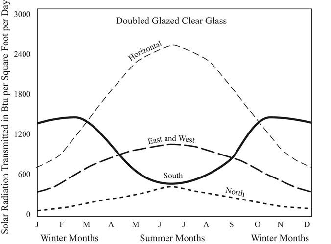
FIGURE 14.1 Solar radiation by wall orientation and season.
Source: Moore 1993.
Since passive solar buildings will need to respond to their local macro and micro climates, it is not likely that what is good design in one location will be good design in another. The result is that energy efficient passive solar buildings can provide national, regional, and local diversity of form and design.
Direct gain is the simplest passive solar strategy (Figure 14.2). The building is oriented to the south. Remember that bioclimatic design suggests an orientation slightly east of south. The window area necessary is approximately 10 to 30 percent of the served floor area. The served floor area is the room that the solar gain is going into. Solar heat will not magically travel across a hall and into a room on the north side of a house. There needs to be an accompanying amount of thermal mass to soak up the solar gain or the room will overheat during the day and be cold at night. The appropriate amount of thermal mass is four to five times the window area, four inches thick. Four inches is the thickness of concrete that heat will flow into and out of in a 24 hour cycle of charging and discharging.
A computer energy simulation can be used to study how much thermal mass is necessary in a direct gain solar heating design (Figure 14.3). An Energy-10 simulation of a passive solar design for Sterling, Virginia, included an infinite insulation layer below the thermal mass concrete floor slab. For both the heating only and the heating and cooling simulations the energy benefit of thermal mass is not improved much beyond four inches thick. The optimum south glass area can also be explored with multiple computer simulation runs. For heating only the optimum window area is indicated by the flat bottom of the curve, which extends from about 16 to 24 percent of the floor area. For heating and cooling the optimum south glass area is in the range of 10 to 15 percent of the floor area (Figure 14.4).
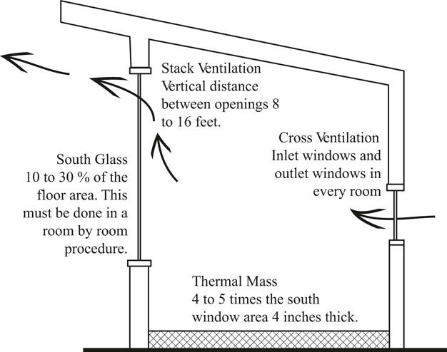
FIGURE 14.2 Passive solar direct gain distributed mass.
The Passive Solar Energy Book (Mazria, 1979) provides the following window area ratios. For winters with average temperatures of 20 to 30 degrees Fahrenheit, set the south window area to 19 to 38 percent of the floor area. And for winters with average temperatures of 39 to 45 degrees Fahrenheit, set the south glass area to 11 to 25 percent of the floor area (Mazria 1979, 119).
The Solar Savings Fraction method suggests 17 to 35 percent south glass for Chicago, with 5,753 heating degree days and a heating design temperature of 3.1 degrees Fahrenheit. It suggests 12 to 23 percent south glass for Washington, DC, with 4,047 heating degree days and a heating design temperature of 20.2 degrees Fahrenheit. And finally, for the milder climate of San Francisco, it suggests 6 to 13 percent south glass with 3,016 heating degree days and a heating design temperature of 40 degrees Fahrenheit (Grondzik et al. 2010, 1646–1649).
The California Energy Commission Passive Solar Handbook, based on multiple Calpas computer simulations, suggests a range of 0 to 33 percent of the floor area in south glass (Niles and Haggard 1980, 90). The insulation level of a house has a large effect on heating energy use and on the amount of south glass area required for passive solar heating. Data from the California Energy Commission Passive Solar Handbook for Alturas, a cold climate, and for San Rafael, a mild climate, illustrates the importance of insulating a house very well before applying passive solar design methods (Figures 14.5 and 14.6).
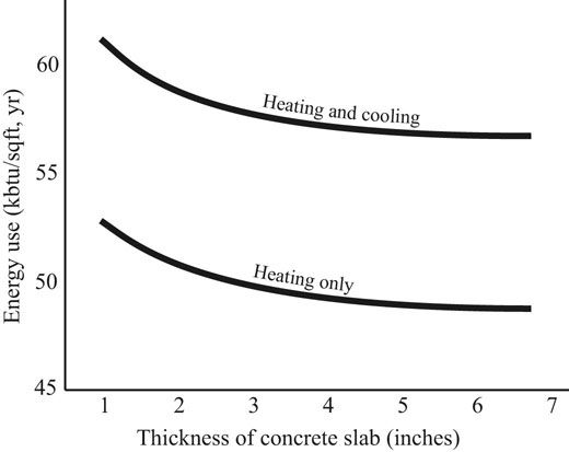
FIGURE 14.3 Energy-10 simulations to determine the optimum concrete floor thickness when used as thermal mass. An R-1000 insulation layer was placed under the concrete floor, which was increased in thickness in inch increments.
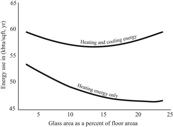
FIGURE 14.4 Energy-10 simulations to determine optimum south window area for Sterling, Virginia. The floor area of the house was 2,000 square feet with 2,000 square feet of 4 inch thick concrete floor as thermal mass.
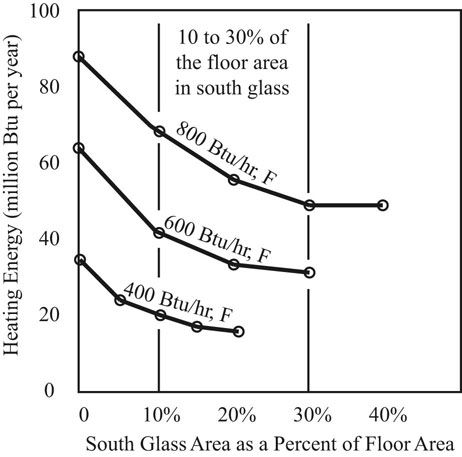
FIGURE 14.5 Computer simulations of passive solar glass area for Alturas, California, with 6,553 heating degree days for three different house insulation levels. The floor area of the house was 2,000 square feet with 2,000 square feet of 4 inch thick concrete floor as thermal mass.
Source: Data from Niles and Haggard 1980.
Thermal mass can be divided into two categories. Thermal mass that is directly warmed by the sun is radiation coupled. Thermal mass that is not directly warmed by radiation from the sun can be warmed by the air in the room. This is called convection coupled thermal mass. Radiation coupled thermal mass is preferred since it will charge the thermal mass quicker and deeper. The thermal mass, usually the floor, is spread out, so it is desirable to spread out the solar gain by bouncing it off light colored surfaces, or blinds. Diffusing glass would be excellent but then the owners of the house could not see out. In all direct gain passive solar configurations, the owners of the building will be living in the collector. Sunlight glaring across the room will probably not be acceptable from a thermal and visual comfort standpoint. In addition sunlight blasting onto furniture and carpets day after day will fade and eventually destroy fabrics. Diffusing the solar gain helps charge the thermal mass more effectively and helps make the passive solar heated room more livable.
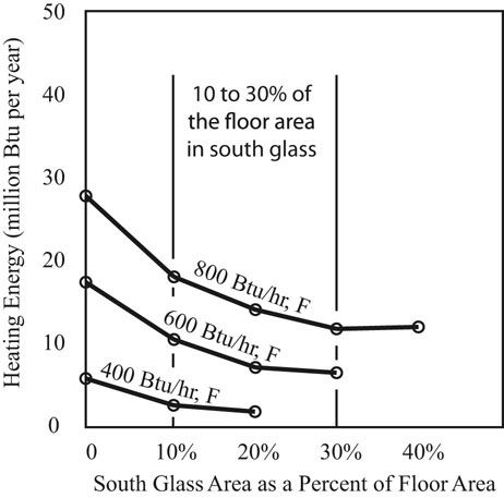
FIGURE 14.6 Computer simulations of passive solar glass area for San Rafael, California, with 2,773 heating degree days for three different house insulation levels. The floor area of the house was 2,000 square feet with 2,000 square feet of 4 inch thick concrete floor as thermal mass.
Source: Data from Niles and Haggard 1980.
It is important to remember that direct gain passive solar window areas and the accompanying thermal mass need to be applied to each room individually. Thus in the usual two room deep house, the southern rooms can have south window areas and thermal mass floors or walls. North facing rooms can either not have passive solar heating, or solar gain can be introduced through clerestory windows. Solar gain through clerestory windows is best bounced off a light colored wall to be distributed evenly over the whole room and the thermal mass in the room.
Finally, the south glass needs to have a horizontal overhang designed to allow the winter sun in and keep out the summer sun (Figure 14.7). The ratio between the extent of the horizontal overhang and the height from the window sill to the bottom of the overhang is 1 : 2. See Chapter 13 on solar shading for a more complete discussion of shading.
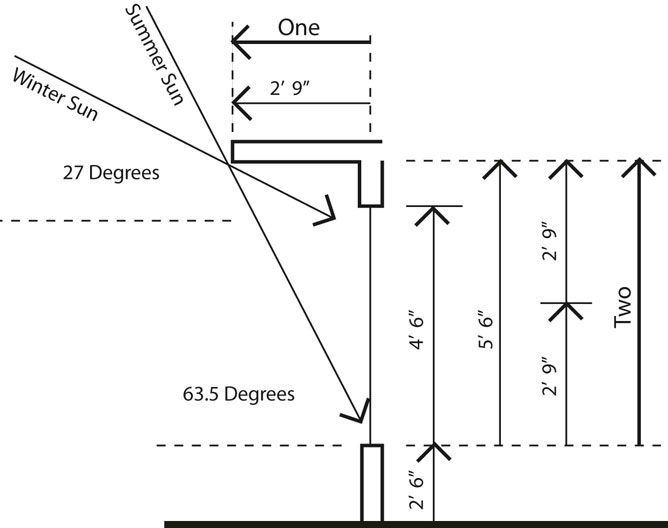
FIGURE 14.7 An optimum overhang blocks out the summer sun and allows the winter sun in.
Eutectic salts can be designed to melt, go from a solid to a liquid, at a defined temperature when they are heated by the sun. Then during the night the eutectic salts will slowly turn back to a solid as they give off heat into the space again at the defined temperature. In an MIT demonstration building the eutectic salts were incorporated into ceiling panels. Blinds just inside the window were mounted with the curved side up. The blinds could then be adjusted to bounce the sunlight coming in through the south windows onto the ceiling. The resulting heating of the eutectic salt ceiling panels caused them to change phase at their defined temperature thus storing thermal energy. The advantage of phase change thermal storage materials is that a much lower volume of material is necessary because of the large amount of heat required to change the state of a material from solid to liquid. The disadvantage of phase change materials is that they turn from a solid to a liquid after being heated. A liquid can leak out of its containment. This creates a potential liability problem for the designer that concrete or brick thermal mass does not have.
In concentrated thermal mass direct gain systems, water tubes are placed just inside the south facing glass (Figure 14.8). The south glass area is the same as direct gain systems with distributed mass. The solar gain heats the water in the tubes. Water is a great thermal mass material. Its volumetric heat capacity is very high and convective currents in the water distribute the heat gained on one side of the tube evenly over the whole volume of water. Heat is transferred to the room in two ways. Room air will be warmed by the tubes and convective air currents will distribute the air to the room. A slow moving ceiling fan can help move heat down to where people are. The water tubes will be warmer than the air in the room at night. The warm surfaces will increase the mean radiant temperature of the room. A room with an elevated mean radiant temperature can provide thermal comfort with a lower air temperature. The water tubes should be painted black or a very dark color on the side facing the window where sunlight hits the tubes. This will maximize the solar gain into the tubes. The side facing the room can be a light color. The modest temperatures being radiated into the room will not be affected much by the color on the room side as long as it is not a metallic surface (Niles and Haggard 1980, 158).
There are two main disadvantages of water tubes as solar storage. The first is that there is a large amount of water in the tubes that can leak out if not maintained over time. The second is that the water tubes need to be placed between the south glass and the room. This blocks the view out the window. The blocked view has one benefit. The sunlight does not blast over the entire room. It is filtered around and sometimes through the water tubes. Good designs take advantage of this filtering of the light.
Thermal storage walls provide an indirect path to heating the space behind them (Figure 14.9). A wall of concrete or other thermal mass material is constructed on the south side of the room to be heated. For a house the wall is approximately 12 inches thick. The outside face of the wall is painted black to absorb the maximum amount of sun. Leaving an air space of four to six inches, a glass wall is placed outside the concrete wall. Solar radiation penetrates the glass and heats up the outside face of the concrete wall. The black outside face of the concrete wall reaches its peak temperature slightly after noon solar time. Solar noon is when the sun is half way across the sky. With a 12 inch thick concrete wall, the heat wave pushed into the wall from the outside takes approximately 8 hours to reach the inside. Thus the peak of the heat wave reaches the inside of the wall at about 8 pm. An 8 inch thick wall will have a time lag of six hours, and a 4 inch thick wall will have a time lag of four hours (Moore 1993, 126). A thermal storage wall should be 20 to 60 percent of the floor area it heats.
The Passive Solar Energy Book suggests 43 to 100 percent of the floor area in thermal wall area for cold climates, and 22 to 60 percent of the floor area in temperate climates (Mazria 1979, 153).
The California Energy Commission Passive Solar Handbook suggests a range of 35 to 75 percent of the floor area in thermal storage wall (Niles and Haggard 1980, 195).
Thermal storage walls are sized for the room the wall is facing into not for the whole house floor area. The temperature swing on the inside face of a 12 inch thick thermal storage wall will be about 25 degrees Fahrenheit, from 65 to 90 degrees Fahrenheit. The outside face of the wall will swing from 55 to 155 degrees Fahrenheit. In a house that is occupied day and night a 12 inch thick concrete thermal storage wall moves heat into the mid-evening hours. A commercial venue that closes at 6 pm or a camp meeting house that closes at 9 pm would call for thinner thermal storage walls with shorter time lags (Niles and Haggard 1980, 195).
FIGURE 14.8 Passive solar concentrated mass.
Vents can be located at the top and bottom of the wall into the airspace between the wall and the glass. The vents allow some of the warm air trapped between the outside face of the wall and the glass to rise and come into the room through the openings in the top of the wall. This process draws room air into the bottom vents, which is then heated completing the cycle. The area of the vents should be approximately 1 square foot of vent per 100 square feet of wall. However, there is a problem with using vents. At night the outside air space between the wall and the glass will be colder than the inside air. If left uncovered, warm room air will enter the upper vents; the air will be cooled and fall down the outside air space between the wall and the glass and come back into the room through the lower vents as a cold draft along the floor. The simple solution is to put light weight flaps of some kind over the upper vents so that air can come in but when air wants to go out the flaps close. Another solution is to avoid the vents in the wall and add some direct gain windows for early in the day solar gain, with the thermal storage wall providing heating for the evening (Moore 1993, 126–127). A Los Alamos study comparing thermal storage walls with and without thermo circulation vents showed that there was very little difference in the solar heat produced (Mazria 1979, 167).
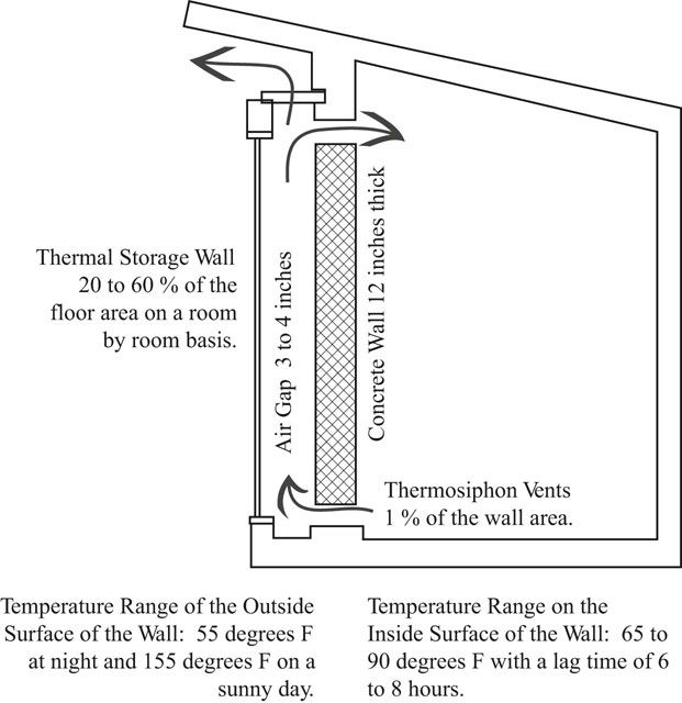
FIGURE 14.9 Passive solar thermal storage wall.
The thermal storage wall needs to be shaded from summer sun and exposed to winter sun, thus an overhang similar in proportions to the overhang protecting a south window needs to protect a thermal storage wall (Figure 14.7). In addition, there needs to be a method of venting the air gap between the wall and the glass to the outside to further minimize heat buildup in the wall during the summer months.
Building a thermal storage wall on the south side of a room cuts off view in that direction from the room. This is a problem that can be partially solved by incorporating windows in the wall. There should be a reveal around the window to minimize glare, and there needs to be glass in the window to maintain the separation of the heated air space along the outside face of the wall.
As in the concentrated mass water tubes of direct gain systems, the inside wall temperatures are only modestly above the room air temperature; thus the color of the inside of the thermal storage wall is not important to radiant thermal transfer. The wall could be a very light color concrete or be painted a light color. Light colors also bounce interior light around creating a more comfortable visual environment.
Solar greenhouses come in two basic variations. One has a concrete thermal storage wall that separates the greenhouse from the house (Figure 14.10). The greenhouse heats up during the day, the thermal storage wall heats up and passes the heat with a time delay to the interior of the house. The other version has a lightweight insulated wall between the greenhouse and the interior of the house. The heat from the greenhouse is transferred to the house through natural or forced convection. The thermal mass to stabilize temperatures from day to night is located in the house, usually the floor. The glass area of the greenhouse should be approximately 30 to 60 percent of the floor area of the rooms in the house adjacent to the greenhouse.
The Passive Solar Energy Book suggests 65 to 150 percent of the floor area of the house in greenhouse glass area for cold climates, and 35 to 90 percent of the floor area of the house in greenhouse glass area for temperate climates (Mazria 1979, 173).
The California Energy Commission Passive Solar Handbook suggests 10 to 50 percent of the area of the house in greenhouse glass area, and it suggests 60 to 160 percent of the floor area of the greenhouse in greenhouse glass (Niles and Haggard 1980, 284).
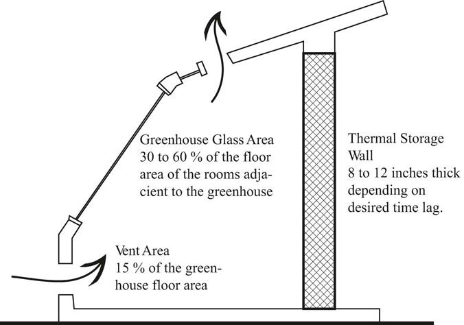
FIGURE 14.10 Passive solar attached greenhouse.
A variation on the basic attached greenhouse design discussed above is to use a fan and some ducting to draw warm air off the top of the greenhouse and blow it through a rock bed storage system under the floor of the house. The rock bed will then either radiantly heat the floor above the rock beds, and/or a fan can draw room air across the rock bed to heat the interior air (Moore 1993, 138–139).
Another variation on the attached greenhouse is to create a two story greenhouse on the south side of a house and then design a double roof and double north wall and a plenum under the house to create what is called a double envelope house. In a double envelope house during the day, air is warmed in the southern greenhouse. It rises up through the plenum across the roof. It starts to cool. As the air reaches the back wall, it cools and drops down the back wall and returns to the greenhouse through the plenum under the house. This slowly heats the ground under the house. At night, the flow reverses. The greenhouse will be colder than the plenum on the north side of the house because the greenhouse is mostly glass and the north plenum is a double insulated wall with a few windows. Thus, air will drop on the greenhouse side and be warmed by the soil under the house and then rise up the north plenum returning to the greenhouse through the plenum over the roof. The daytime and nighttime flows of air create a milder temperature surrounding the house than the outside air temperature.
Another form of passive solar system is to set up a collector that warms air and is located below the level of the house. A rock bed is used to store heat for use during the night and through cloudy periods. Locating the air collector below the rock bed and the rock bed below the house allows natural convection to move the warm air around. Air warmed in the collector will rise up into the top of the rock bed and then fall through the rock bed warming the rocks before returning to the bottom of the air collector. Air can also be delivered directly to the house from the collector if needed during the day. During the night, air will rise through the warmed rocks and flow into the house and the colder return air will drop back to the bottom of the rock bed (Moore 1993, 147–150).
There is potential for the air collector to reverse flow at night and cool down the rock bed. This can be avoided by designing the exterior glazing on the air collector so that the upper edge of the exterior glazing is lower than the inlet and outlet location at the top of the collector (Niles and Haggard 1980, 263).
The addition of a fan to push the air around provides freedom to locate the air collector and the rock bed anywhere. One example of this freedom is to create a glass plenum on the south elevation. Place blinds in the plenum and a rock bed below the floor. A fan can then draw warm air created when the sun hits the blinds through the rock bed under the house and then back to the house where the air can then reenter the glass plenum. Heat can be transferred to the house by radiation through the floor and or by a fan. A fan driven system also has the option of drawing cooling air at night through the rock bed thus providing cooling during summer days.
The vast majority of passive solar buildings are direct gain systems because they are simpler and more straightforward. Thermal mass located as the floor is less expensive than thermal mass in a wall, which requires more structural reinforcement.