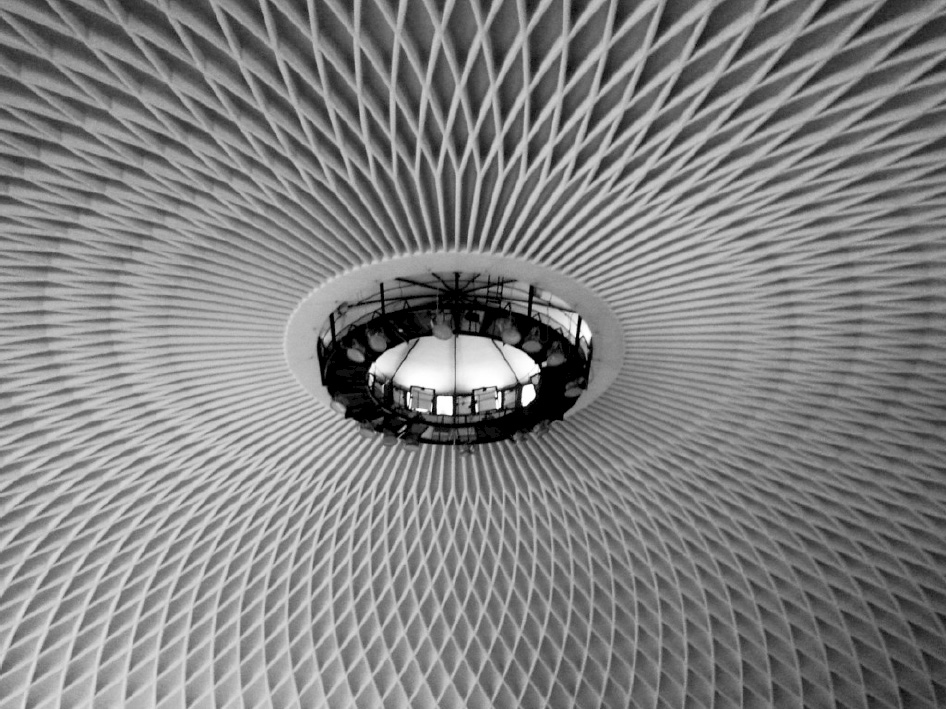
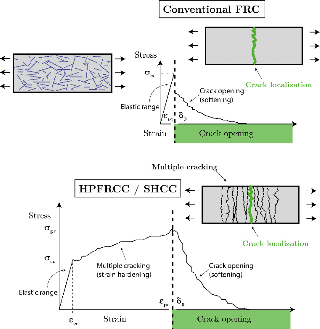
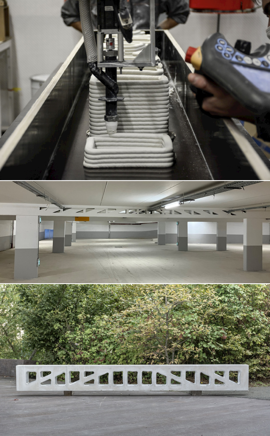
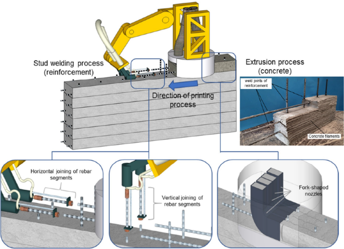
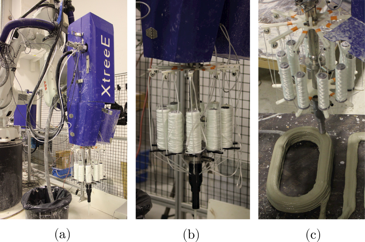
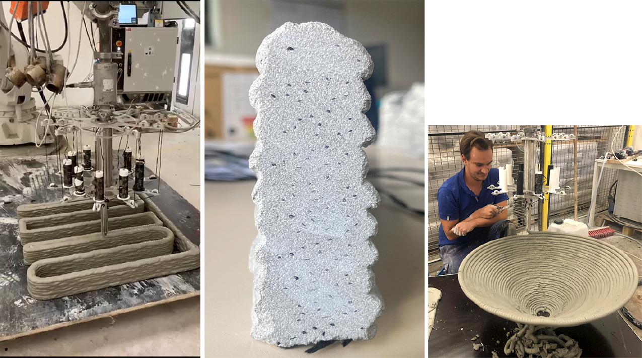
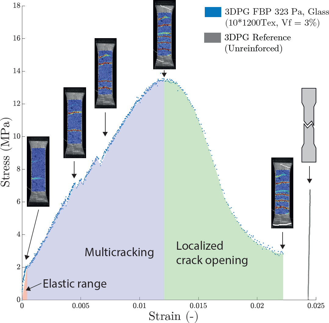
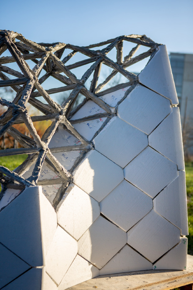
Jean-François CARON1, Nicolas DUCOULOMBIER2 and Léo DEMONT1 1 Laboratoire Navier, École des Ponts, Marne-la-Vallée, France 2 XtreeE, Rungis, France With a tensile strength of just a few MPa and brittle behavior, cementitious mortars cannot legally be used unreinforced under tensile loading configurations. This is true today for cast structures, and will be so in the future for printed structures. Reinforcing printed mortar is therefore a highly strategic issue for the development of the technology. In this chapter, we first review the history and technologies of cement and concrete reinforcement in order to understand the mechanisms involved. In the second part, we take stock of initiatives concerning 3D printing in particular, and detail an original technology for reinforcing mortar with long, continuous fibers. Cementitious materials have a much lower tensile strength than compressive materials, as well as a high degree of brittleness. This behavior is due to the presence of natural micro-cracks, which form during setting and propagate under load to the point of failure, since the toughness of these matrices is low. A micro- or macro-crack will have a greater impact on the material’s behavior, and the more it is oriented perpendicularly to the tensile forces. The solution, therefore, is to “sew” these cracks with a suitable reinforcement, allowing the material to be discharged locally in favor of the reinforcement system. Two types of reinforcement exist for concrete and mortar: those that we shall refer to as structural, such as reinforcement and cables, and those that are more on the scale of the material, such as fiber reinforcements. We will come back to these two families in the following section so as to fully understand the mechanics of these mixes, and to identify the issues and problems that will remain the same for reinforced printed mortars. The oldest and best-known technique, due to its widespread use, is reinforced concrete, that is, concrete reinforced by the addition of metal reinforcement to take up tensile stresses throughout the structure. The idea is attributed to the French engineer Joseph Lambot, who in 1848 first came up with the idea of reinforcing the cement of his agricultural ferries, and then that of a small boat, with a steel lattice. He patented the concept in 1855, which became known as “Ferrocement” (Naaman 2000). Numerous developments followed, notably in the building and civil engineering sectors, with no fewer than 262 patents registered between 1886 and 1906, leading to the first regulations in France that same year. There were two opposing approaches. The first proposed post-and-beam construction systems, with the progressive use of steel sections with larger cross-sections, known as “concrete reinforcing bars” or steel rebars. This approach, initially promoted by François Hennebique, is the one that finally took hold and still accounts for a significant proportion of today’s constructions. The second approach, on the other hand, uses fine-diameter reinforcements forming a steel network to ensure a strong adhesion between the reinforcement and the matrix. This system, promoted by Cottencin, was taken up by Italian architectural engineer Pier Luigi Nervi in the middle of the last century, who went on to develop the concept of fine steel mesh. “Ferrocement” then became a technique that enabled architectural feats such as the hangar at the Orbetello airfield (Italy) in 1940 or Rome’s Palazzetto dello Sport in 1957 (Figure 6.1) to be achieved, with its staggering efficiency and inspiring aesthetics. However, its delicate implementation requires special expertise, and its high cost condemns it to niche applications. We will come back to this in the conclusion to this chapter, as the underlying concepts were so visionary and adapted to today’s means. Another method for reinforcing concrete structures, developed and patented by Eugene Freyssinet in 1928, is prestressing. By superimposing a sufficiently high local compressive stress on the external load, this method allows the material element to work only in compression, thus avoiding (if this prestressing does not relax over time) the problem of its poor tensile strength. This method also has the advantage of enabling dry assembly of prefabricated concrete elements, widely used in the manufacturing of bridges and overhanging structures. These two reinforcement methods are sometimes used simultaneously, as part of structural systems that compensate for material weakness. Figure 6.1. Palazzetto dello Sport, Rome, 1957 (GiulioCesare, archidiap.com/opera/palazzetto-dello-sport/, original dimensions, licensed under CC BY-SA 4.0) There are also reinforcement methods that improve mechanical behavior at the level of the material itself. In the case of concrete, this is the role of aggregates, which increase the compressive strength and ductility of mortar by providing dissipation mechanisms. Similarly, the addition of a small quantity of fibers with high tensile strength improves tensile behavior, notably by enabling the sewing of micro- or macro-cracks. Two sub-categories can be distinguished depending on whether these composites are made from short, generally randomly oriented fibers, or from continuous fibers aligned in one or more given directions. If we are particularly interested in tensile mechanical properties, the addition of continuous fibers provides a greater improvement in the mechanical behavior of the composite in the fiber direction(s) compared to the addition of the same volume of short fibers, whose orientation is often random. However, in the first case, the gain in strength is maximum only in the direction of the continuous reinforcements, which is referred to as anisotropic behavior. In the second case, the tensile behavior of the representative elemental volume (REV) remains virtually isotropic, since it is improved in all directions. Short-fiber reinforcement is generally achieved by introducing the fibers directly into the mixer during matrix production. However, their addition causes a significant drop in the fluidity of the mix (Martinie 2010). The volume fraction introduced is therefore limited (a few percent by volume), as is the reinforcement obtained, and the effect on rheology is highly dependent on fiber slenderness (length/diameter). The aim of adding these fibers is to slow down or even prevent crack propagation in the cementitious matrix and improve the ductility of the whole by avoiding sudden, localized failure. They must therefore be sufficiently anchored in the cementitious matrix to be able to take up forces on either side of the crack to limit its opening, but also be able to loosen before fracture to provide ductility by dissipating energy at the fiber/matrix interfaces. The type of effect a fiber has on overall behavior is closely linked to its diameter (Rossi 2001; Betterman and Ouyang 1995; Li and Leung 1992; Rossi 1998; Brandt 2008), which is generally correlated with its length. Sufficiently fine fibers may have an effect on microcracking and delay localization, but their short length limits their action to small crack openings, that is, before localization. This results in low tensile ductility. However, larger diameter fibers act once localization has been activated. They therefore do not increase strength, but do provide a certain ductility (see Figure 6.2). Figure 6.2. Effect of fibers according to diameter and size (adapted from Betterman and Ouyang 1995). Numerous short fibers have been developed for the reinforcement of cementitious materials (Brandt 2008; Hamidi and Aslani 2019). Metal fibers are still the most widely used reinforcement for cementitious materials, and make up the family of metal fiber concretes. To limit their influence on rheology, the slenderness value is often around 60 (Rossi 1998). They generally have a relatively weak bond with the cementitious matrix. As a result, numerous geometries have been developed to optimize their anchorage: twisted, with hooks, etc. (Brandt 2008). The functioning of metal fibers with complex geometries is described in Chanvillard (1992). As far as mechanical behavior is concerned, fiber concretes made from a single type of metal fiber always lead to the achievement of moderate reinforcement characterized mainly by a reduction in brittleness, illustrated on the force-deformation curve in Figure 6.3(a). There are two strategies for increasing the performance of fiber-reinforced cementitious composites (high-performance fiber-reinforced cementitious composites (HPFRCC)). These involve either increasing the quantity of fiber by modifying the manufacturing process (which is difficult), or taking advantage of the synergy obtained by using fibers of different sizes and diameters (generally three types of fiber), which results in a significantly higher fiber content while maintaining good workability (Rossi 2001, 2013). The behavior is then characterized by the presence of an additional phase of positive strain-hardening behavior, even in direct tension, between the elastic and softening behavior, illustrated in Figure 6.3(b). The parameters σcc and σpc are then generally defined, corresponding to the value of the stress associated with the appearance of the first macrocrack and the maximum stress, representing the ultimate tensile strength ft. The range of behaviors obtained depends on the type and quantity of fiber used. In the case of metal fibers (Wille et al. 2014), yield strength and maximum direct tensile strength can reach 15 and 20 MPa, respectively, for strains of 0.03% and 0.5%, respectively. Other types of fiber, notably synthetic fibers, have been introduced more recently. Softer and more slender, they are generally centimeter-long (Brandt 2008) and have a wide range of mechanical properties. This has given rise to a new family of cementitious materials known as engineered cementitious composites (ECC), offering a wide range of behavioral characteristics. For example, in direct tension (Li et al. 2020), strain-hardening cementitious composites (SHCC), composed of a fine cementitious matrix and a limited fraction of synthetic fibers (Li 2003), have a tensile strength of less than 5 MPa, but a strain-hardening behavior up to a very high strain-to-failure value of the order of 5% (Li 2003; Jun and Mechtcherine 2010). Figure 6.3. Diagram and characteristic behavior curve (adapted from Betterman and Ouyang 1995). Even if we exclude from this description metal reinforcements, as described in the introduction (irons and grids), there are continuous reinforcement solutions using long fibers or threads. Mainly used to make prefabricated structural elements or to repair old structures, they have taken advantage of the recent development of low-cost mineral and organic fibers, enabling the production of high-weight rovings, textiles and nets with excellent mechanical properties and insensitivity to corrosion. There are several possible arrangements for the fibers in the roving. They can be straight, known as laminated roving, or twisted. Their particular mechanical behavior has been studied in detail by Chudoba et al. (2006). We could also mention fabric reinforcement made from the same threads, which differs from netting in its woven structure (Peled et al. 1994), but whose implementation principle is similar. These materials are sometimes called textile reinforced concrete (TRC) or textile reinforced mortar (TRM), and were first proposed for slender structures containing very fine elements (Hegger and Voss 2008; Hegger et al. 2018), which could then be pultruded (Peled and Mobasher 2006), and to reinforce aging structures (Brückner et al. 2006; Mechtcherine 2013; Kouris and Triantafillou 2018). It should be noted that these cementitious composites, like ferrocement, are made from a cementitious matrix of low particle size (absence of centimetric aggregates), often including silica fume and mineral fillers. The threads are made from mineral or synthetic multi-fiber rovings, generally AR glass fibers. The individual fibers are of the order of 10 μm in size, and the threads contain a few thousand filaments (Hegger et al. 2006). The simple tensile behavior of laminated composites presents three phases: Naturally, reinforcement is less effective when loading is not oriented in the main thread directions, and the quality of impregnation of the fibers by the cementitious matrix plays an essential role in the behavior of TRCs, since it dictates the transfer of load from the matrix to the reinforcement. Tensile mechanical behavior in these main directions is in fact very similar to that of unidirectional brittle matrix composites, especially unidirectional ceramic matrix composites (CMCs) (Curtin et al. 1998; Xia and Curtin 2000; Castelier et al. 2010; Chateau et al. 2015). However, the latter benefit from far more sophisticated and costly processes, and differ in terms of much higher fiber content, and far superior impregnation qualities (vacuum and/or gas phase). Here, the particular structure of multi-fiber yarns and the imperfect impregnation of the cementitious matrix through the network of fibers that make up the yarn limit the utilization rate of the reinforcement and lead to damage to its mechanical properties during loading (Häußler-Combe and Hartig 2007). This is referred to as reinforcement efficiency, defined as the ratio of the tensile strength of the composite to the bare strength of the reinforcement (Hegger et al. 2006). After these reminders concerning the reinforcement of cast mortars, we take stock of initiatives concerning the reinforcement of printed materials. Changing the process from pouring/pumping to printing/extrusion does not totally change the issues or the solutions. The main part of what has been described above will be found in the proposals for the reinforcement of printed structures, inserts, prestressing, short or long fibers, etc. However, the new process fundamentally proposes a different way of designing. Instead of a volumetric vision of the objects to be built, induced by the formwork and casting tools, it transforms them into a surface vision induced by the laying process. It thus brings new rules and imperatives into play, opening the way to new constructive systems and, consequently, to new modes of reinforcement. For example, it allows us to rethink the optimization of the shape according to a given load, just as the ancients did naturally. Nubian vaults were built without formwork, as were Freyssinet’s prestressed arches and Nervi’s funicular vaults, all of which benefited from cheap, abundant skilled labor, and thus compensated for the high cost of materials. The material is becoming expensive again, at least in environmental terms, and today if labor is scarce and expensive, digital technology and robotics can make up for it. This means that structures can be reexamined in terms of their shape, and pure compression, for example, can be sought without the need for direct reinforcement. In Carneau et al. (2020, 2019), printed arch and vault systems are proposed. Additive manufacturing of cementitious materials is seen as a new approach to masonry with continuous brick beds, something Pegna (1997) had already noted in 1997. There is no need for material reinforcement here, but what about the strength of the joint between layers. Experience has shown that a suitable procedure can avoid so-called cold-jointing, that is, weak joints, and even achieve a strength equal to that of the mortar at this singularity. Many studies have been carried out on this subject, however, and (Keita et al. 2019) show that the difference in strength between the deposited material and the transition zone is in fact mainly a function of the drying of the free surface before the new layer is deposited. There is also a maximum overlap time, tr, to avoid the appearance of a joint of lower strength. Khoshnevis (2004) has proposed the use of staples to improve the strength of the interface between two successive layers, and a number of studies have also focused on this subject. Alongside these reflections linking form, material and structure, and in order to avoid tensions, the economic deployment of the technology involves more conventional applications – quasi-vertical walls, horizontal beams and slabs – for which reinforcement of the printed material is of course necessary. Numerous approaches have been proposed in the literature, although there is as yet no reference solution. These proposals can be classified according to a criterion proposed in Asprone et al. (2018b), which groups reinforcement methods according to the time of application. For some of them, reinforcement is applied a posteriori, inspired by traditional reinforcement methods. For others, it is integrated directly into the initial batch of material. For the latter, reinforcement is carried out simultaneously with in-line printing, in the immediate vicinity of the printing nozzle. We now review the techniques available to date. Here, the structure is reinforced a posteriori, that is, once it has been printed. The classic reinforced or prestressed concrete techniques mentioned above are used. It is possible, for example, to produce structures in printed cementitious materials, incorporating recesses for inserting reinforcing bars or prestressing tendons secured by injection of a grout as proposed in Figure 6.4(c). The advantage of this type of process is that it can be rapidly deployed on construction sites, since existing dimensioning methods integrated into the regulatory framework are directly applicable. Figure 6.4. A posteriori reinforcement: (a) column with printed formwork and BFUP XtreeE (Duballet 2018); (b) printed formwork for concrete casting reinforced with traditional reinforcement cages (photo courtesy of Spie-Batignolles); (c) printing with pre-stressed cable reservations © Richard Buswell. Another way of using 3D printing to create complex regulatory structures is to print the formwork into which the concrete will be cast and reinforced using traditional methods. This is what the Chinese company Winsun or the French one Spie-Batignolles (see Figure 6.4(b)) proposes, for example, by positioning reinforcement in a printed mold. Another example is XtreeE, which prefers to use ultra-high-performance fiber-reinforced concrete, which is simpler to process, to make the column illustrated in Figure 6.4(a). In Maitenaz et al. (2021, 2024), another example concerns a methodology for optimizing a Eurocode-compliant beam using such printed formwork. Potential concrete savings are significant: thanks to a parametric study, they have been estimated at 48% on average for residential building beams. A prototype is shown in Figure 6.5, where the formwork and robotic configuration are also visible and a scale. One realisation by ISC Vinci and Chantiers Modernes construction is shown. Figure 6.5. Prototype of an optimized reinforced concrete beam with printed formwork (Maitenaz et al. 2024) and an application by Chantiers Modernes Construction in Drancy, France. A major drawback is that today’s regulations do not allow formwork cement to be taken into account in dimensioning, as the level of collaboration between hardened printed cement and freshly cast cement is unknown. So, even if this method allows for complex shapes, in some cases it can be handicapped by the additional cost, including environmental costs. Other more recent proposals involve reinforcing printed structures with external reinforcements. In Asprone et al. (2018a), a beam is proposed in which the compressive parts are produced by robotized extrusion in cementitious material, while the tensile forces are taken up by an external metal skeleton. In Salet et al. (2018), a footbridge is made up of a number of printed mortar voussoirs connected by prestressing cables. A natural idea, of course, is to integrate the reinforcement into the cementitious material right from the initial mixing stage and extrude fiber-reinforced concretes as described above. To obtain a pumpable mortar, the fibers must be flexible and therefore have a limited diameter. The most commonly used fibers are synthetic (carbon, PVA and PE) or mineral (glass or basalt). In order to maintain a mode of rupture by interface decohesion and/or to avoid blocking the pumping and extrusion system, the length of the fibers is also limited (≈ 10mm). Finally, to guarantee a sufficiently low yield stress, the volume proportion is limited, generally less than or equal to 2% (Ogura et al. 2018). An interesting result concerns the orientation of fibers during extrusion (Ma et al. 2019; Panda et al. 2017; Hambach and Volkmer 2017; Hambach et al. 2016; Li et al. 2020), which significantly increases reinforcement in the direction of extrusion. The study by Ma et al. (2019), on the other hand, suggests that interlayer interface strength is reduced when reinforcing fibers are added. As with cast-reinforced concretes, depending on the dimensions and fiber content, the mechanical strength of the reinforced material may be improved but the ductility reduced (Hambach et al. 2016), or it may be highly ductile with reduced mechanical strength (Soltan and Li 2018; Ogura et al. 2018; Zhu et al. 2019). The opportunity to obtain this type of ductile, positive-hardening behavior with a mortar, is very interesting for construction and it enriches the family of ECC mentioned above for cast solutions (Li et al. 2020). The mechanical strengths obtained in the extrusion direction can be higher than those of cast composites (Soltan and Li 2018; Ogura et al. 2018), thanks to a phenomenon of increased multi-cracking in the deposition direction. In Zhu et al. (2019), a PE fiber volume ratio of 2% enabled a very high strain-to-failure in the deposition direction of the order of 10% for a flexural strength of 20 MPa. A similar formulation was recently used on a large scale to produce a 1.5-m column (Li et al. 2020). Earlier work (Hambach et al. 2016) had achieved flexural strengths of 100 MPa with 3% carbon fiber, albeit with a very high yield stress making extrusion difficult. It is highly likely that, through optimal choices of fiber type and size, mortar quality and process suitability, the effectiveness of this type of reinforcement for printed mortars will improve significantly in the years to come. The idea here is to concomitantly print the mortar and place the reinforcement. These approaches are more sophisticated and generally developed for nonstandard concrete structures and as part of an integrated digital process based on advanced robotic manufacturing strategies. A number of research projects have focused on the direct adaptation of the principle of reinforced concrete using steel bars, or rebars (see, for example, Classen et al. (2020); Perrot et al. (2020); Hass et al. (2022)). This is an interesting approach as it offers the prospect of rapid acceptance and use by the industry. Most solutions involve the robotic insertion of small bars, rather like nails, into the printed stack, either perpendicular to the stack direction or at an angle. This has the advantage of also reinforcing the interfaces crossed, as these can represent a weakness (cold joints) for the structure if there is poor adhesion between the layers due to too rapid drying of the layer that will receive the new deposit. Classen et al. (2020) proposed such a process called additive manufacturing of reinforced concrete (AMoRC), a hybrid process consisting of an intermittent stud welding process and a continuous concrete extrusion process. Segmented steel reinforcing bars are assembled to form a three-dimensional reinforcing mesh and simultaneously embedded in the extruded concrete (Figure 6.6). In Perrot et al. (2020), experiments with this type of nail reinforcement on different mortars, here already printed, demonstrated effective reinforcement if the orientation of the nails is correctly chosen and if the surface of the nails is sufficiently rough to ensure a good interface with the mortar (Figure 6.7). In Geneidy et al. (2020), U-shaped reinforcing elements, or “staples”, staple the layers together vertically during printing. The staples penetrate several layers, but also interlock to form a reinforcing network. Finally, in Gebhard et al. (2020), a device incorporating a reel enables needles to be deposited horizontally between the layers in order to obtain reinforcement in the axis of the strands, thus approximating to conventional reinforced concrete. Figure 6.6. 3D printing process (AMoRC) for reinforced concrete, concrete extrusion and reinforcement welding (Classen et al. 2020). Figure 6.7. Reinforcement with nails between layers and bending curves showing improved ductility (Perrot et al. 2020) Smart dynamic casting and mesh mould developed at ETH Zurich (Lloret et al. 2015) offer another robotic concept that enables the continuous production of a three-dimensional welded reinforcing mesh, used here as formwork, and the concrete filler. The technology is based on the ability of this porous cage to retain the mortar, which has sufficient yield stress and viscosity properties while mitigating hydrostatic pressure. Such sacrificial filter forms have been proposed for conventional concrete in France (Dipy 1992, 3DR 1999 (SF3DR 1999)) and then in China (Ren and Wang 2005). They allow for complex shapes and hydrostatic pressure reduction of over 80%. The Empa’s NEST building in Zurich is a showcase for experiments using these new 3D-printed concrete technologies for free-form columns and roofs produced without formwork. Another option is to mechanically integrate a generally continuous, unwound reinforcement at the nozzle, such as micro-cables, chains or metal grids (Bos et al. 2019; Lim et al. 2018; Bos et al. 2017; Marchment and Sanjayan 2020) (Figure 6.8). Particular attention must be paid to the quality of the interface between the reinforcement and the cementitious material, which determines the composite performance of the assembly. Figure 6.8. Co-extrusion of reinforced strand, reinforced by continuous reinforcement: technical devices for a metal chain (Bos et al. 2019). Mineral fiber elements are of course widely investigated, for example, recently in Mechtcherine et al. (2020a) or by the authors of this chapter in Ducoulombier et al. (2020). The former uses a thin, narrow strip of mineral-impregnated carbon fiber (MCF) unwound downstream of the nozzle onto an already printed layer, which is covered by the current deposit. In Mechtcherine et al. (2020b), to ensure proper impregnation of the carbon fiber roving, a pre-impregnation line using very fine mortar is set up upstream to prepare the web to be deposited. The wires are then placed mechanically between the layers upstream of the printed strand. A variant of the MCF process called ProfiCarb (Neef and Mechtcherine 2022) reconditions prepreg yarns into coils that are driven directly by the flow of a single-component mortar (Figure 6.9). Several reinforcements, in this case six yarns of twisted carbon fiber, can then be dispersed in the cross-section of the coil (Figure 6.9). Figure 6.9. ProfiCarb process and view of the six yarns nozzle (Ivaniuk et al. 2022; Neef and Mechtcherine 2022). This latter process is very close to the flow-based-pultrusion (FBP) concept proposed by the authors of this chapter (Ducoulombier et al. 2020) and which will be detailed in section 6.3. This type of approach enables more homogeneous, “in-line” reinforcement and avoids technologies and motors for guiding and driving the reinforcement, which complicate the process and reduce formal possibilities, such as pronounced curves for example. Last but not least, we should mention the Injection 3D Concrete Printing (I3DCP) process (Hack et al. 2020), which enables the injection of one or more continuous reinforcements. This does not involve 3D concrete printing by extrusion, but rather printing in a yield stress fluid bath serving as a support. All of these continuous reinforcement solutions are, of course, similar in spirit to traditional reinforced concrete techniques. They reinforce preferentially in a preferred direction (Asprone et al. 2018b), induce anisotropy and are therefore very effective for the bending behavior of the structure, even for moderate reinforcement volume fractions. To go further, they need to fit as closely as possible into the framework of formal freedom offered by robotics. The following paragraph focuses on the FBP concept (Ducoulombier et al. 2020; Caron et al. 2021), which we believe meets the need for efficiency, simplicity and adaptability to new building system proposals. An in-line approach and a material track strongly inspired by the technologies of long-fiber composite materials, since it involves reinforcing the layers with continuous fibers aligned and distributed in a homogeneous, nonlocalized manner, is therefore proposed. We briefly describe the technology, the experiments and the performance of the reinforced material. The technology described in the patent by Caron and Ducoulombier (2020) is called FBP. By controlling the rheological behavior of the cementitious matrix, small-diameter continuous strands (glass, basalt, etc.) are routed and impregnated without any motorization (Figure 6.10). The resulting material, known as anisotropic concrete, is homogeneously reinforced in a single direction, opening up new possibilities. Indeed, it cannot only improve the strength and ductility of the hardened material, but also contribute to better handling of fresh beads during deposition, enabling more complex sloping or cantilevered courses, as we shall see later (Figure 6.12, right). A first prototype was developed at the Navier laboratory and was adapted to a bicomponent head from XtreeE mounted on an ABB 6200 six-axis robot (Figure 6.11). As seen in Chapter 2, in concrete 3D printing by extrusion, there are two main technologies, mono-component or bicomponent. The first deposits a layer directly pumped into a batch of prepared mortar of the right consistency for stacking. A powerful pump is required, as the mixture is relatively thin (a few thousand kPa), a yield stress that evolves quite slowly but irremediably to a consistency too high for printing. Two-component technology prints a much more fluid material (a few hundred kPa), strongly accelerated by an additive just before printing. The initial mixture is therefore easier to pump, more stable and allows greater freedom, since the operator can modify it continuously according to what is required or needs to be corrected. Our FBP process is closely linked to this technology, which makes it easy to introduce fibers into a fluid material that hardens rapidly. Impregnation is highly effective and drive remains assured as the mortar quickly builds-up itself around the fiber. First prints have been made with glass, basalt and carbon fibers, up to 6% by volume. Details of the process technology can be found in Demont et al. (2021). To take things further, a second industrial prototype is currently under development in collaboration with XtreeE. Figure 6.10. Fiberized printing device: (1) coils, (2) pulleys, (3) guides and (4) drive head (Caron and Ducoulombier 2020) Figure 6.12, the XtreeE prototype, shows the cross-section of a hardened bead reinforced with 1% carbon fiber in the center. On the right, it shows a corolla that would not be printable without fiber, as the rings are rapidly subjected to tensile stresses that mortar alone cannot withstand. Figure 6.11. Prototype 1, Navier laboratory, with fiberglass printing. Figure 6.12. Prototype 2, XtreeE: printing with carbon fibers, evenly distributed as shown by the cross-section of strands in the center. Printing of a fibrous structure with tensile rings (right). Tensile and flexural tests have been carried out on cords reinforced with various levels of glass fiber and basalt. Other tests are in progress with other fibers such as carbon or PVA. The specimens consist of a tensile layer and a flexural multi-layer. Figure 6.13 shows the type of tensile behavior obtained with 3% fibers (in this case glass), and the high ductility achieved thanks to the diffuse microcracking made possible by the presence of the fibers. This type of behavior is also found in bending, and details can be found in Caron et al. (2021). Meter-scale tests on beams with reinforced intrados are currently underway, and initial results are very promising. Figure 6.13. Tensile test of a 3% glass fiber-reinforced specimen and image correlation revealing the progressive appearance of cracks. On the left, in gray, an unreinforced specimen. Due to the low mechanical properties obtained in tension and the regulation framework, reinforcing 3D mortar prints is an imperative and a highly strategic research and industrial issue for the commercial development of the technology. While there are no off-the-shelf solutions today, a number of initiatives are already providing answers to the various situations encountered. Often inspired by the long and rich history of reinforcement technologies for cast cements and concretes, they also try to draw on the new tools available today, such as robotics, parametric design and materials science. In the first part, we briefly recalled the important elements in the history of “reinforced concrete”, the material mechanisms involved and the challenges in terms of strength and ductility control. These are concentrated in the term “engineered cementitious composite”, in other words the formulation of tailor-made cementitious materials. In the second part, we take stock of existing initiatives, and classify them according to whether they reenforce the printed structure, the printing material, or in-line. The former have the advantage of being able to be rapidly implemented in real-life situations, via demonstrators, and thus promote the technology. The second type is very promising, as this type of fiber-reinforced mortar is already widely accepted and regulated in the community. Technical progress is still needed to improve the achievable fiber content and workability of mortars, but initial results in terms of strength and ductility are very encouraging. Finally, in-line reinforcement is certainly an interesting avenue, perhaps more in tune with the spirit of technology and construction 4.0. This should enable more massive reinforcements, in competition with conventional steel systems for concrete, more flexible in use and adaptable according to the need and the object to be reinforced. However, these latter systems still pose a number of problems: anchoring and flexibility of reinforcements, technological simplicity and suitability for the formal performance expected of 3D printing. This is because, as already mentioned, the latter transforms a volumetric vision of the objects to be built, induced by the formwork and casting tools, into a surface vision driven by the application process. 3D printing is therefore expected to offer new structural systems. We cite here a particular example of a concrete lattice, illustrated in Figure 6.14, a concept presented in Duballet et al. (2019) and realized via robotized manufacturing by free deposition (Duballet et al. 2020). In this type of structure, the elements only work in tension or compression. The anisotropy provided by an in-line robotized fiber extrusion process would therefore be particularly suitable and totally disruptive in terms of concrete construction systems. In the final section, we focus on an initiative by the authors of this chapter, that is, FBP. This type of in-line reinforcement could meet several key challenges: good anchorage of the fibers in the cementitious matrix, technological simplicity and a source of inspiration for new construction systems. In conclusion, as mentioned in the introduction, the competition between two reinforcement systems proposed at the end of the 19th century – the Hennebique system (reinforced posts and beams) and the Cottencin system (thin ferrocement slabs) – could well be replayed in favor of the latter, thanks to new printing processes and in-line reinforcement as proposed by FBP. This would make it possible to reinvent freer, lighter structures such as those proposed by Candela or Pier Luigi Nervi (Figure 6.1). In his own words, Nervi wanted to “get away from plank architecture” by eliminating the need for wooden formwork, and serve a vision that combined material, form and structure to create more virtuous buildings. Figure 6.14. Curved concrete truss presented at the “FORM and FORCE” international conference in Barcelona in October 2019. (Photo credit: Stephano Borghi).
6
Reinforcement of Printed Structures
6.1. Introduction, a few reminders about the reinforcement of cementitious materials
6.1.1. Structural reinforcement of cementitious materials
6.1.2. Fibering of cementitious materials
6.1.2.1. Reinforcing cementitious materials with short fibers

6.1.2.2. Continuous reinforcement of cementitious materials
6.2. Reinforcement methods for additively manufactured cementitious materials and structures
6.2.1. A posteriori reinforcements

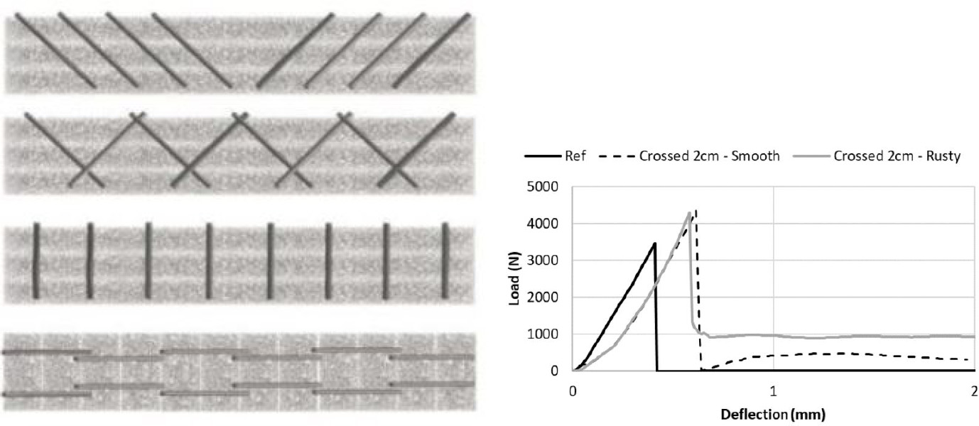
6.2.2. Mortar reinforcement
6.2.3. In-line reinforcements
6.3. Details of a special in-line reinforcement, the flow-based-pultrusion concept
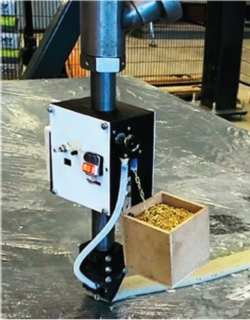
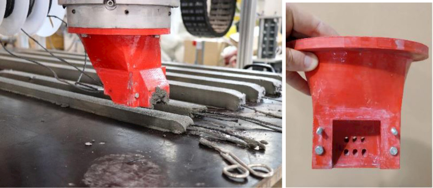
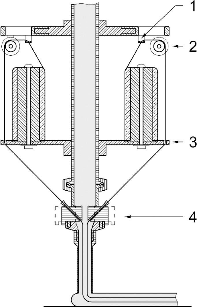
6.3.1. Technology
6.3.2. Prototypes and devices
6.3.3. Characteristics of the hardened and reinforced material
6.4. Conclusion and outlook
6.5. References
Notes