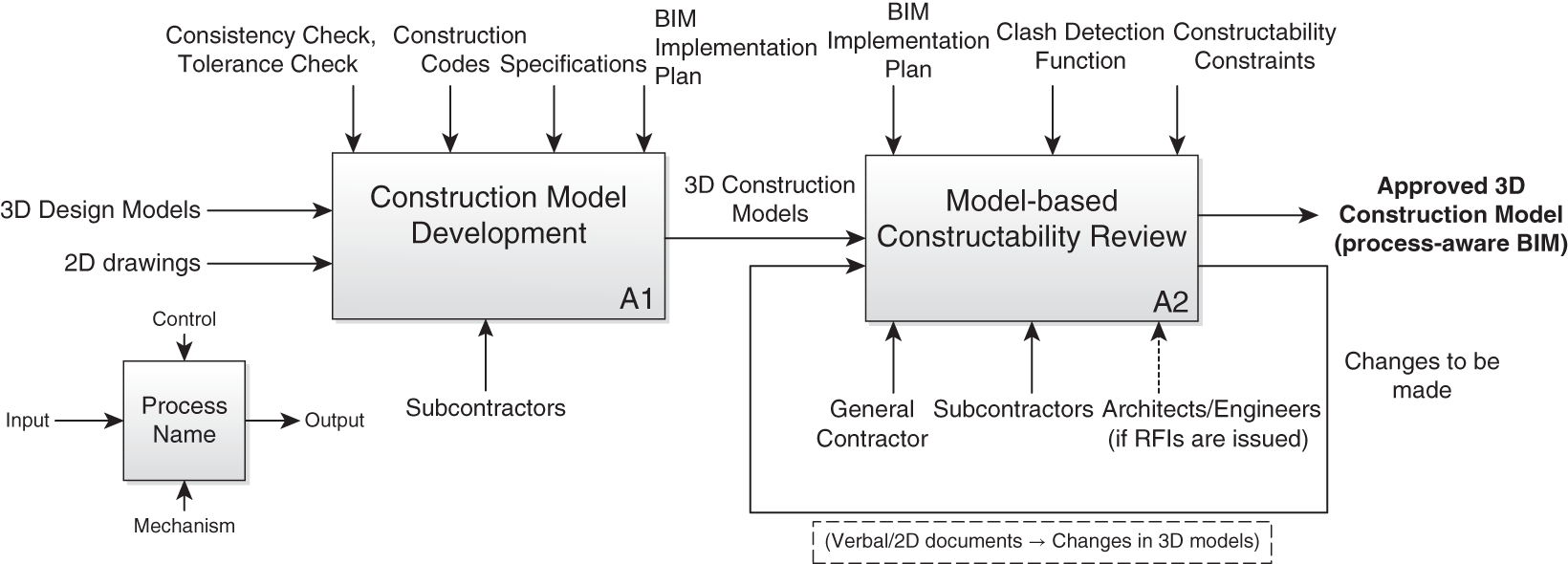
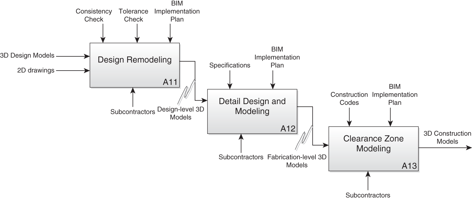
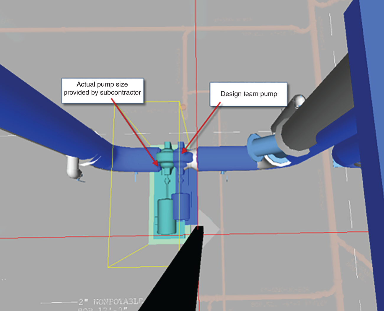
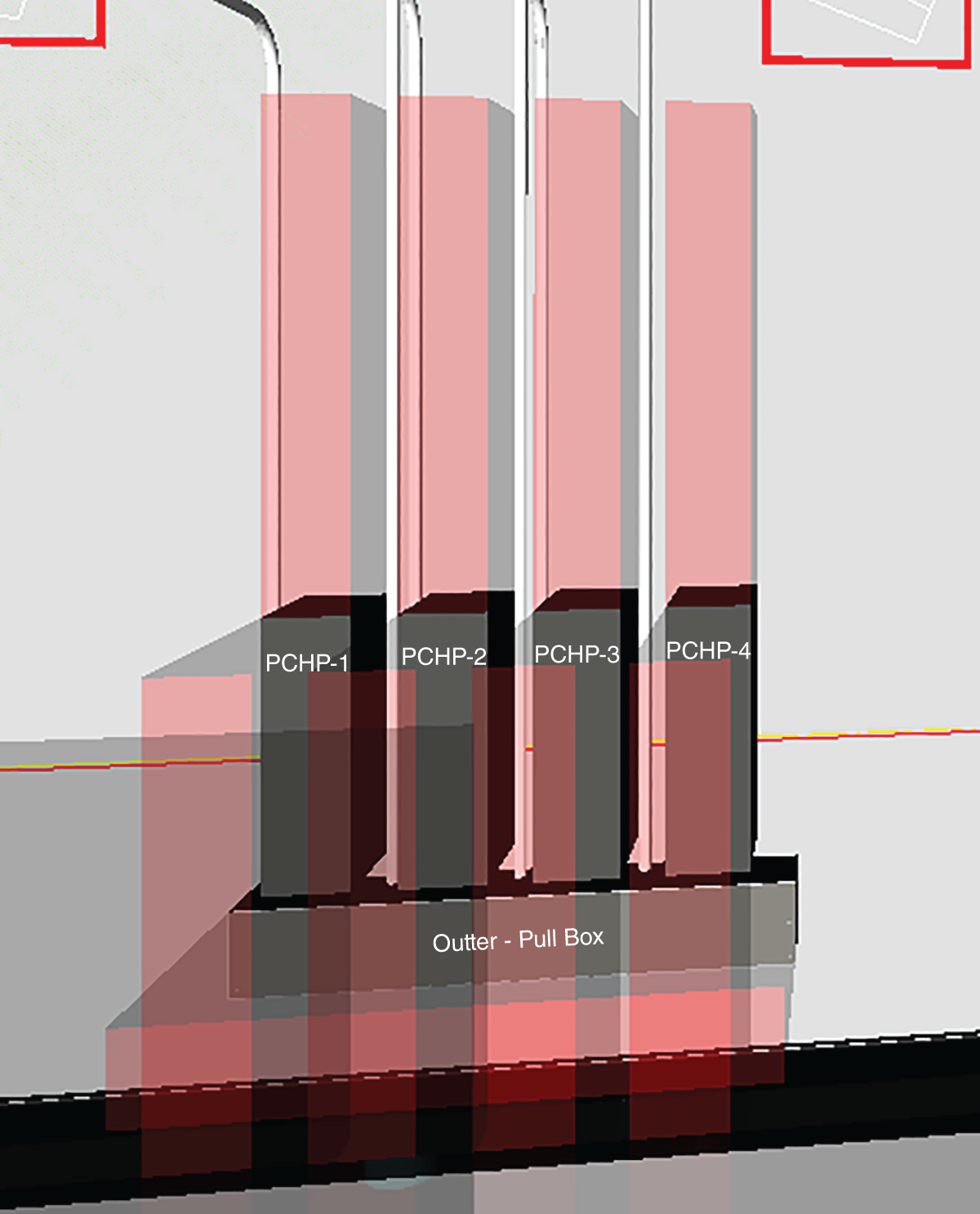
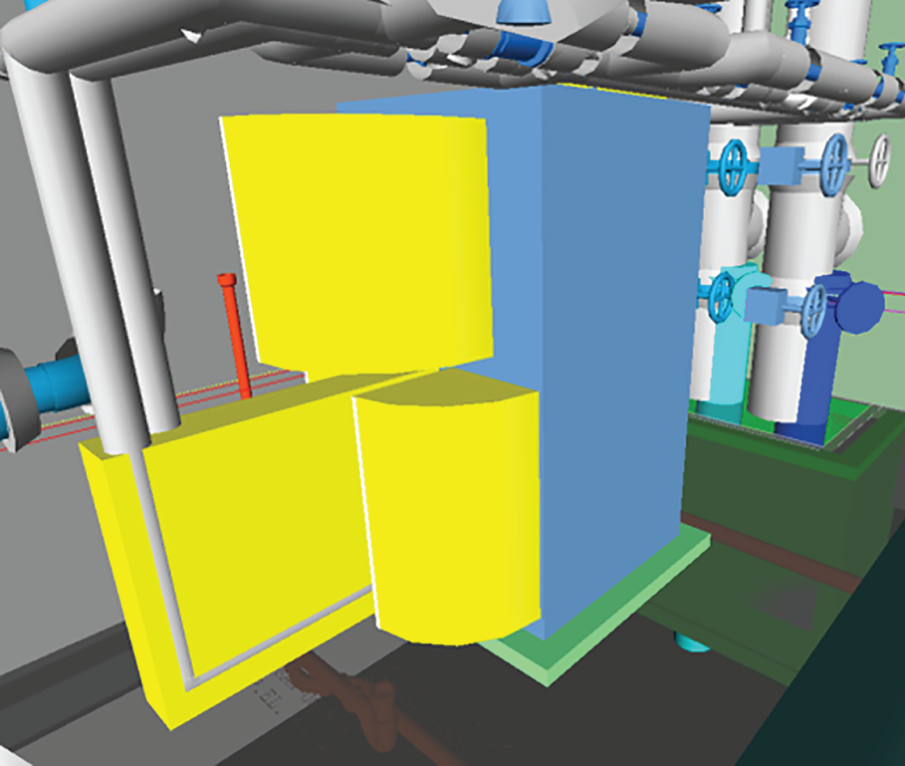
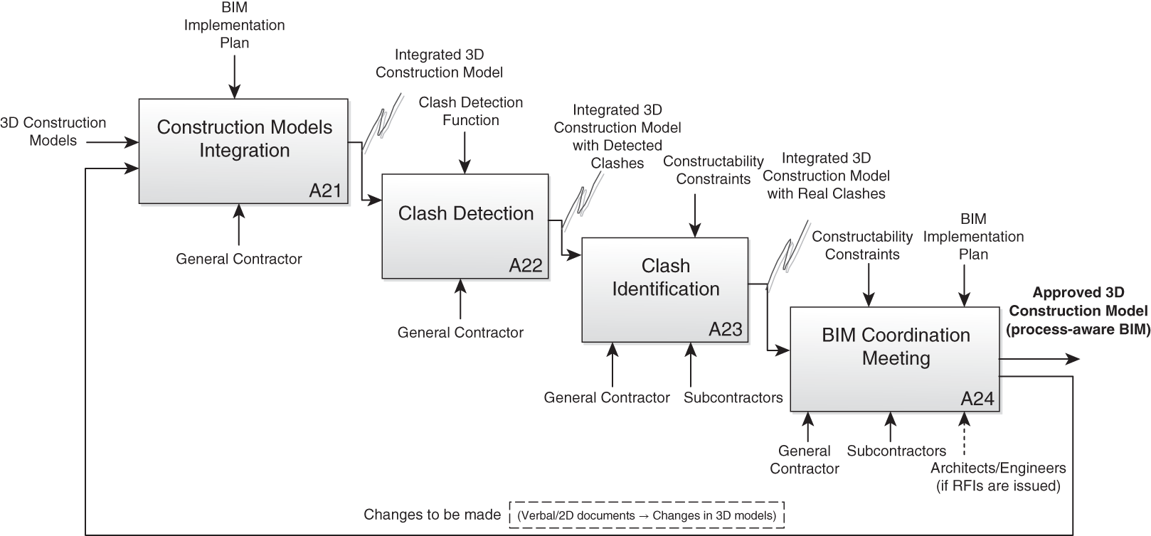
Designers, including architects, engineers, architectural engineers, and design consultants, are responsible for generating a design model, which serves as the base model for the design coordination process. They also update their design model(s) during the construction phase based on design coordination or constructability assessments, or any other design changes. This chapter covers specific guidelines for designers involved in design coordination and discusses the roles and responsibilities of the designer. The chapter also describes how the design team interfaces with the VDC team, as well as other project stakeholders, such as subcontractors and owners. A case study of a facility expansion project is presented and describes the information required to integrate process information into BIM, by documenting current practices of constructability review process and the challenges of implementing this process in the design phase. The case study illustrates how a model created by designers can serve as the base model for a constructability review. Fragmented organizational divisions in the architecture, engineering, and construction (AEC) industry and traditional procurement methods (such as design-bid-build) result in a sequential separation between design and construction processes. This fragmented nature often leads to information loss, duplication, or inaccuracy and further gives rise to productivity loss, schedule delays, cost overruns, increased litigation, and unsatisfactory production quality (de la Garza 1994). The annual cost due to inadequate interoperability in the United States capital facility industry in 2002 was quantified to be $15.8 billion (Gallaher et al. 2004). In 2019 dollars, that is estimated to be near $20.8 billion (in United States dollars), when simply adjusting the original estimate for inflation. The importance of collaboration among project participants and integration between processes has been widely recognized (Gallaher et al. 2004). In recent decades there have been significant research efforts focusing on including construction information in the design development process to enhance constructability of designs (e.g., Odeh 1992, Dzeng 1995, Aalami 1998, Wang and Leite 2012), since constructability is considered a major factor that has consequential impacts on the success of construction projects (CII 1993; Waly and Thabet 2002). Due to several factors, including the fact that design professionals usually having little knowledge/experience in construction practices, local considerations, the availability of different resources, and construction methods (Waly and Thabet 2003), the integration of constructability knowledge in design requires efficient communication and collaboration between the design team and construction team. Information technologies such as building information modeling (BIM) and virtual design and construction (VDC) provide significant support to such a collaborative environment and design-construction integration and have been increasingly used to improve design quality and management efficiency in the AEC industry (Eastman et al. 2011). The current use of BIM in the United States building construction industry has been mostly limited to a small number of tasks such as design or trade coordination (Hartmann and Fisher 2007, Becerik-Gerber and Rice 2010, Mostafa and Leite 2018). The information-sharing power of BIM has not been fully utilized in terms of facilitating communication between designers and builders in the design phase. As one BIM engineer working in a building with complex mechanical, electrical, plumbing, and fire protection (MEPF) systems described it, “In the virtual world, we can fit 10 pounds of stuff into a 5-pound bag.” In other words, in projects with complex and convoluted MEPF systems, objects may fit perfectly in the model but fail to be installed on site because of constructability or installation issues, which further suggests that inadequate process consideration is involved in the design model. Moreover, current model-authoring tools are still lacking real-time collaboration mechanisms and means to integrate constructability issues into the model: for instance, smart models that could help designers proactively identify potential constructability issues. A constructability review is usually conducted by general contractors (GCs) and subcontractors in the preconstruction planning phase after the design is substantially completed. Requests for information (RFIs) are issued by contractors to designers if necessary changes have to be made in the design; designers respond to the RFIs with approval/disapproval for the requests for changes. It was estimated that designers spent 40–50% of the total work hours in a project addressing changes (Koskela 1992). Recently, there have been increasing efforts toward product-process model integration using information technology (IT) (Karhu 1999; Wang and Leite 2016); but most focus on including construction process information such as sequences or cost into the product models, usually developed by the construction team for preconstruction planning. Previous research on concurrent engineering in the AEC industry provides strategies for considering process information in the design process, such as early involvement of specialty contractors (Gil et al. 2000a) and postponed commitment of design documents (Tommelein et al. 1991). Despite stressing the importance of constructability input to the design model, previous research fails to provide enough guidance on the actual interaction between designers and builders through BIM. It is easy to understand what knowledge specialty contractors may contribute to the early design, whereas how such knowledge can be extracted and represented in the design model remains unclear. Since the design is not only a representation of client requirements but also accountable for construction and operational processes in terms of constructability, usability, and maintainability, it is important to consider these forthcoming issues as early as possible in the design process (Womack et al. 1990, 323; Ward et al. 1995). Planning decisions made at the preconstruction stage are crucial to the successful execution and completion of any project (Waly and Thabet 2002). Concurrent engineering (CE), which is also referred to as design for manufacturing (DFM), has been widely accepted as an effective practice of assessing manufacturability in the product development stage in the manufacturing industry (de la Garza 1994). It is indicated that specialty contractors and fabricators should also be involved early in the design process to provide insight on process efficiencies in designs (Gil et al. 2000b). Glavinich (1995) described two methods for improving constructability and decreasing design-related problems during the construction process: (1) design phase scheduling, and (2) in-house design-phase constructability reviews. Lottaz et al. (1999) developed an internet-based SpaceSolver that supports project participants to refine the space of design solutions without committing too early. Guided by the principles of lean manufacturing, Gil et al. (2000a, 2000b) proposed the integration of the early design stages with construction and advocated the involvement of specialty contractors in the early design. Despite a lot of effort in the past to interlink design and process planning, a method for capturing specialty contractors’ construction knowledge with the production model and making it available in the early design stage is still not available. In the manufacturing industry, different practices have been adopted, such as moving people from their organizations to work directly with suppliers, creating conditions so people who work for suppliers can work in their assembly plants, and providing incentives for suppliers to get involved earlier in design (Gil et al. 2000a). Hence, there is a large potential to facilitate concurrent engineering with the support of IT, which is a research area that has not been fully explored. This chapter covers specific guidelines for designers involved in design coordination and discusses the roles and responsibilities of the designer. The chapter also describes how the design team interfaces with VDC teams, as well as other project stakeholders, such as the GC, subcontractors, and owners. A case study of a facility expansion project is presented and describes information required to integrate process information into BIM, by documenting current practices of constructability review process and the challenges of implementing this process in the design phase. The case study illustrates that a model created by designers is capable of serving as the base model for a constructability review. Although design coordination is a collaborative process between multiple project stakeholders (e.g., owner, designers, general contractor, and subcontractors), the process of coordinating designs involve first detailing an architect’s and engineer’s design into a fabrication model (i.e., LOD 400). It is important to note that MEPF subcontractors’ development of a fabrication model is not design service. Rather, it is a translation in 3D of an engineer’s design, which aims at enabling efficient and cost-effective construction and installation of that design. In other words, engineers remain responsible for design, and contractors and subcontractors remain responsible for construction and installation. Designers, hence, have the role of ensuring that their design intent is maintained in a clash-free and fabrication-ready model. Before any designers are signed to a project, the use of BIM should be stipulated in contract language. Each architect and engineer should be required to abide by the BIM-related processes described in the project’s BIM project execution plan (PxP) to ensure successful design coordination. After each design coordination session, the designer implements the changes discussed in the model. Designers should ensure that the model is updated for the next design coordination session and the design changes are communicated for construction execution, especially given that the architectural and structural models usually serve as the baseline for all subcontractor models. Table 6.1 illustrates sample roles and responsibilities of designers, which can be included in a BIM PxP. The specific responsibilities of designers shown in Table 6.1 are further detailed in the following sections. At the start of the BIM design coordination sessions, the designers should provide a base 3D model to the GC for distribution to the subcontractors; the model should be in at least level of development (LOD) 300, which minimally includes architectural and structural systems. The base model allows the subcontractors to develop a 3D model for their individual scope of work (e.g., mechanical, electrical, plumbing, or fire protection). TABLE 6.1 Sample designer roles and responsibilities established in a BIM PxP While the GC runs a large part of the BIM design coordination sessions, the designer may also be required to employ at least one BIM manager. The designer’s BIM manager is responsible for updating the design model during the design and construction phase. After each design coordination session, the designer implements the changes discussed in the model. Designers should ensure that the model is updated for the next design coordination session and the design changes are communicated for construction execution, especially given that the architectural and structural models usually serve as the baseline for all subcontractor models. The subcontractors commence their work once they receive design drawings and specifications from a project’s architect(s) and/or engineer(s). The information in the designer’s drawings is augmented and detailed by the subcontractors, with the development of shop drawings and details needed for installation, ensuring that the engineer’s design intent and prescribed system performance are maintained. The GC may relay RFIs from subcontractors and/or other designers to the designer, to ensure that their design intent is maintained during the design coordination process. Due to the RFIs, changes may have to be made in the design; designers respond to the RFIs with approval/disapproval for the requests for changes. Any design changes need to be reflected in the base model. Designers also interface with other project teams, such as the owner, GC, and subcontractors. The main BIM-related interface points are discussed next. The owner has a key role in setting up the project for success in terms of design coordination, by establishing ground rules and expectations early on. Once the design team is selected by the owner, the owner should review, evaluate, and comment on the designer’s BIM PxP, if the owner chooses to require one from the designer as well as the GC. Note that in the United States, the common practice is that the GC leads the BIM implementation process, especially with regard to design coordination. Once the project is underway, the owner should regularly check the model(s) and/or participate in weekly design coordination sessions. It is advisable that the owner conduct two kick-off meetings that are specifically BIM-related. The first is at the design phase, with the entire design team, as well as any major consultants. This meeting should be led by the design team and its BIM lead. A second meeting should be held once the GC or construction manager is selected and should include the design team, GC team, and major subcontractors/construction trades. This meeting should be led by the GC team and its BIM lead. Additional BIM review meetings can be called by the owner as the owner deems necessary. Such meetings can include compliance checks of the BIM PxP, visual examinations of federated models, and review of design coordination processes. Also, if an owner’s representative is in place, it is advisable that this individual attends the weekly design coordination sessions led by the GC’s BIM manager. The owner should also facilitate model handover between designer and GC, assuming there are two separate contracts in place, between owner and designer, and owner and GC. While the GC runs a large part of the BIM design coordination sessions, the designer may also be required to employ at least one BIM manager. The designer’s BIM manager is responsible for updating the design model during the design and construction phase. The GC’s BIM manager uses the designer’s BIM manager as the point of contact for BIM issues related to the design. The GC relays any RFIs to designers. If any design is impacted due to and RFIs, the designer should reflect those changes in the base model. At the start of the BIM design coordination sessions, the designers should provide a base 3D model, which minimally includes architectural and structural systems, to the GC for distributions to the subcontractors. It is the MEPF subcontractors’ responsibility to develop their own 3D models for their scopes of work considering the base 3D model; collaborate in the design coordination process with the GC, designers, and other subcontractors; and construct their respective systems following the agreed-upon coordinated model. But before any subcontractors are signed to a project by the GC, the use of BIM should be stipulated in contract language. Each subcontractor should be required to abide by the BIM-related processes described in the GC’s BIM PxP to ensure successful design coordination. Each subcontractor should employ a 3D/BIM technician and/or respective lead project managers who will attend design coordination sessions, are responsible for resolving model conflicts, as well as implement changes in the model discussed in design coordination sessions. This case study was conducted from November 2011 to March 2012 on a facility expansion project that was under construction at the time in the United States and originally presented by my former Ph.D. student Li Wang in the 2012 European Group Intelligent Computing in Engineering (Wang and Leite 2012). The project provided approximately 10,000 gross square feet of high-density data center space adjacent to an existing building. The project included 6.2 MW of power, 3,700 tons of cooling, and an 8,000 square foot stand-alone central plant. The procurement method was construction management at risk (CM at risk). The whole project was broken down into two packages. Package 1 included underground facilities, and package 2 included the above-ground facilities. Sources of evidence for this case study included semi-structured face-to-face interviews, document analysis, and field observations. Interviews were conducted with the project manager, superintendent, and BIM coordinator. Documents analyzed included the master building information model that combined architectural, structural, and MEPF models; shop drawings; design specifications; meeting minutes; construction schedules; and RFIs. On-site observations included weekly owner meetings, foreman meetings, and design coordination meetings. Based on data collection and analysis, the current practices were summarized and the challenges of implementing a constructability review in the design phase were identified. The constructability review process and associated activities in the case study are formalized and presented in three IDEF0 models. In the design phase, the design team developed 85% complete construction documents (CDs) including 3D design models, 2D drawings generated directly from the models, technical documents, and specifications. The constructability review was conducted at the stage of preconstruction planning. An IDEF0 diagram was used to formalize the constructability review process (shown in Figure 6.1). The constructability review in this case study primarily consisted of two processes: construction model development and a model-based constructability review. In the preconstruction phase, the subcontractors were given access to the 3D models and 2D drawings prepared by the design team. All design models were distributed to team members using a web-based file transfer service. The subcontractors used the 3D design models as references for creating fabrication-level models (also referred to as construction models) for their respective scopes of work. (The associated activities involved in the construction model development process are presented in chapter 7’s case study.) Before approving the subcontractors to generate shop drawings from their construction models, the GC went through a model-based constructability review process to ensure that the design was conflict-free and constructible in the field. From preconstruction planning to construction, all construction models were shared using Bentley ProjectWise. The activity-level IDEF0 model for the model-based constructability review process is presented in section 6.4.2. This BIM implementation plan, shown as a “control” element in Figure 6.1, was developed by the GC to address the targeted BIM uses on the project and delineate roles and responsibilities of each company. Once the coordinated model was approved by the project team, the model and related drawings and specification were ready to be used for fabrication. FIGURE 6.1 IDEF0 diagram of the constructability review process The subcontractors developed their own models even though they were given access to the 3D design models created by the design team. In order to understand why construction models were rebuilt and what additional information was included, two approaches were used for data collection. One was semi-structured interviews with the BIM engineer, superintendent, and foremen. The other was model comparison analysis between the construction and design models. The results from the interviews and model comparison analysis were synthesized and presented in an IDEF0 diagram to illustrate the construction model development process (Figure 6.2). The first step (A11) was remodeling the facilities based on CDs. According to the requirements in the BIM implementation plan, construction models should include 3D objects in design models with accurate placement and dimensioning (shape and size). While the design and construction models were overlapped for model comparison, slight geometric differences of the pipe alignment and system placement were identified. Since system placement in the remodeling process might not be 100% accurate, subcontractors were obligated to check if the variance is within a predetermined tolerance. This tolerance is referred to as model tolerance and is different from field tolerance that varies for different trades based on their specifications. This model tolerance is a measure of the accuracy of the model objects as they are placed in the 3D construction BIM. Maximum model tolerance for any model that existed for this project was 1/16″ (approximately 1.6 mm). During design remodeling, subcontractors could change the dimensioning of some systems when the designers left the choices of system selection to the contractors. One example from the case study is shown in Figure 6.3: the contractor chose a pump that was bigger than the one shown in the design, which was also acceptable according to the specification. While modeling the pump with its actual size, the subcontractor found that there would be a collision between the pump and a nearby model object. Therefore, the subcontractor moved the pump slightly to the left to avoid constructability issues. FIGURE 6.2 IDEF0 diagram of the construction model development process (A1) FIGURE 6.3 Pump size and placement variance between the construction model and design model The second step (A12) was adding the level of detail and detailed system design in the construction model. There was less detail in the design model as compared to the construction model. The scope of work of the architect/engineer (A/E) did not include providing details in the design models at the fabrication level. The responsibility and flexibility were left to the contractors and subcontractors for designing system details and identifying a suitable method of constructing the intended elements in a feasible manner. For example, every element above 1″ (approximately 2.5 cm) diameter should be modeled for all the systems under the MEPF trades, while design models only included mechanical piping over 3″ (approximately 7.6 cm). Moreover, there were systems that were not modeled or not completely modeled in the design model, either because the designer did not have the expertise to model them or because it was out of the A/E’s responsibility. One example was the fire protection system design, which was only provided in the construction model. The third step (A13) was to model clearance zones, which are areas in which no other systems can exist. Clearance zones modeled in this project included code-required clearances, access zones, and other spaces that should be left empty due to constructability issues. Figure 6.4 shows an example of code-required clearance zones that were modeled around the electrical boxes. Working areas were modeled around the equipment that required access for operations and maintenance (Figure 6.5). One example of access zones is shown in Figure 6.5, where the yellow objects represent the access zone and swing area around panel doors. FIGURE 6.4 Clearance zones modeled around electrical boxes The main difference between design and construction BIM is the level of detail, because the designers either provide flexibility to the contractors or do not have enough information to model the detail. Another important difference is process modeling by the contractors; spaces such as clearance zones and access paths are only modeled by subcontractors in construction models. Since the differences are mostly supplementary information, it is possible that the design model is revised/upgraded to the level of detail needed for the constructability review. By adding information for detailed system design and process representation, the input requirements of the constructability review process can be met in the design phase. FIGURE 6.5 Access zone and swing area around panel doors In the constructability review process, clashes and constructability issues are solved in the construction models. Before approving the subcontractors to generate shop drawings, the GC went through a model-based constructability review process by combining all the construction models developed by different subcontractors into one integrated model, checking existing conflicts or constructability issues among different trades and resolving all potential problems. The process of model-based design review is illustrated in Figure 6.6. After the BIM engineer received all construction models from subcontractors, he combined the models (A21) and ran automatic clash detection (A22) using Autodesk Navisworks Manage. By running automatic checking, all collisions in the model were identified. Thousands of clashes might be shown in such a result. According to the BIM engineer, nearly 50% of the clashes identified automatically were false positives. The most import step was to clean out the false positives and identify real clashes (A23). The most common false positives include acceptable clashes and double-counted clashes. One example of an acceptable clash was the installation rod for piping passing through the structural steel at the ceiling for attachment purposes. The real clashes identified by the BIM engineer were then discussed at coordination meetings. FIGURE 6.6 IDEF0 diagram of the model-based constructability review process (A2) The GC held BIM coordination meetings (A24) every Monday, Wednesday, and Friday mornings. The purpose of these meetings was to produce a design that minimized conflicts between trades and ensured constructability. In the meetings, the BIM engineer (part of the GC) went through each identified clash with the involved subcontractors, discussing constructability issues and possible solutions with related subcontractors. If there were major changes to be made, an RFI was issued. The A/Es confirmed if the changes could be made. After each meeting, the subcontractors addressed the identified changes, updated their models, and sent the revised models to the GC. And then another iteration of the design review was held until there were no additional changes to be made. Once the coordinated model was approved by the project team, the model and related drawings and specification were ready to be used for fabrication. The main challenge of formalizing this process is related to the control named constructability constraints, which is mostly conducted by visual checking. For a large majority of construction projects, the current approach to identify soft clashes (i.e., inadequate working space, insufficient resource allocation, and time-space conflicts) is manual-based. Soft clashes are usually identified by an experience-driven thinking process with the help of model visualization. Soft clashes exist when there is no physical conflict between elements, but constructability problems will occur during the installation process. For example, the mechanical subcontractor found that the piping layout where the chilled water pipes entered the machine room in the design allowed a tight space to weld the flanges on the pipe, and thus proposed another layout design that allowed greater spacing for easier welding of the flanges. Specialty contractors have experience and knowledge of space requirements during construction that should be accounted for in early design in order to build efficiently. Instances of such knowledge concern access paths to bring in equipment and materials, and clearances around routings so laborers have space to work and move around safely. Involvement of specialty contractors’ knowledge in early design can prevent designers from developing solutions that are inefficient to build or that cannot be built. The mechanism of hard clash detection can be easily used in the design phase. However, visual checking is challenging to implement, because it depends on one’s experience and observation capability. In the design process, designers do not have the same experience the subcontractors have, and thus a formalized constructability method is needed that transforms tacit knowledge to computer interpretable processes. Tacit knowledge seldom exists explicitly, and people often cannot easily articulate it (Wang and Leite 2012). As reported by Hanlon and Sanvido (1995), 83% of constructability knowledge is tacit knowledge that resides in the heads of experts. In contrast, explicit knowledge exists in some kind of support that makes it more independent from individuals. Explicit knowledge is easier than tacit knowledge to share and communicate among people who work in the same organization. By transforming tacit knowledge into explicit knowledge that can be articulated or simulated, the constructability checking process can be replicated in the design phase. One approach to make this transformation is to represent the information in a building information model in the form of objects, such as modeling clearance boxes, installation paths, workspaces, and temporary structures. Another solution is to learn from the experience of constructability reviews in preconstruction planning. Since the constructability review is an iterative process, it can be considered a source of lessons learned. It is important for the construction team to document the constructability issues with an explicit explanation of the rules, as well as the comparison of the proposed solutions with the original design. However, it is observed that the discussions and information generated in coordination meetings are not formally documented. The drawbacks and risks of non-formalized documentation are: (1) lack of reference material of the decisions made; (2) limited access to information; and (3) loss of knowledge generated during the process. If the knowledge is not documented, it is difficult to learn from. Communication and documentation tools that can more efficiently and accurately track and record information generated during the trade collaboration process can be applied to address this challenge. This case study described information requirements for the constructability review of a facility expansion project. The current constructability review process was illustrated in three IDEF0 diagrams. The case study illustrates that a model created by designers is capable of serving as the base model for the constructability review. Detailed system design and process modeling are required for coordination at the operational level. Mechanisms of the constructability assessment process need to be formalized. Detailed documentation of the current constructability review process is essential for formalizing reasoning mechanisms, to reduce the reliance on subcontractors’ tacit knowledge in the design phase. Such conclusions serve as the basis for further research, which aims at investigating the information exchange, generation, and transformation between the design team and the construction team using BIM in order to formalize such information and develop a semi-automated constructability review process, supported by IT. This chapter described specific guidelines for designers involved in BIM-based design coordination and discussed the roles and responsibilities of the designer. The chapter also described how the design team interfaces with the VDC team, as well as other project stakeholders, such as subcontractors and the owner. A case study of a facility expansion project was presented and described the information required to integrate process information into BIM, by documenting current practices of the constructability review process and the challenges of implementing this process in the design phase. The case study illustrates that a model created by designers is capable of serving as the base model for constructability review.
Chapter 6
Specific Guidelines for Architects and Engineers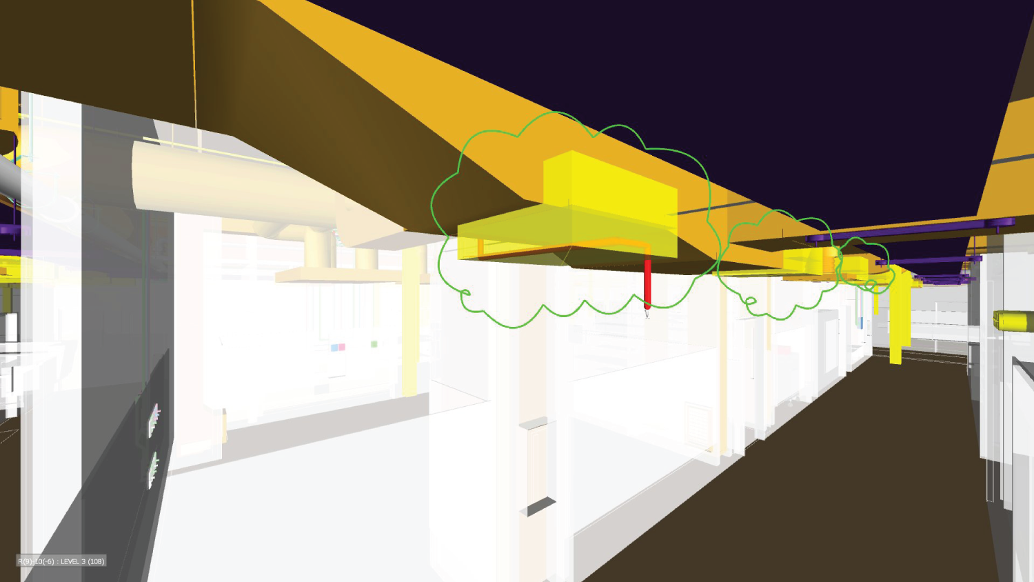
6.0 Executive Summary
6.1 Introduction
6.2 Role of Designers in the Design Coordination Process
6.2.1 Generating the Design Model (e.g., Architectural, Structural)
BIM-related role
BIM-related responsibility
BIM manager
6.2.2 Updating the Model with Design Changes
6.2.3 Point of Contact for BIM Issues Related to Design
6.3 Interfacing with Other Stakeholders
6.3.1 Owner
6.3.2 General Contractor
6.3.3 Subcontractors
6.4 Case Study: Facility Expansion Project
6.4.1 Current Practice of the Constructability Review
6.4.2 Construction Model Development
6.4.3 Model-Based Design Review Process
6.5 Summary and Discussion Points
References