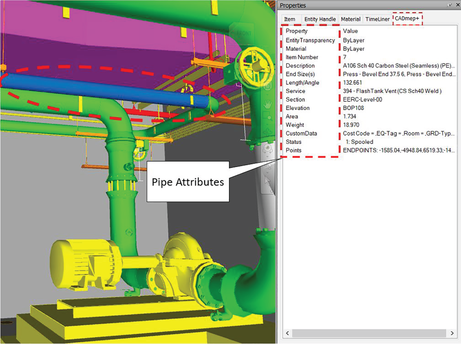
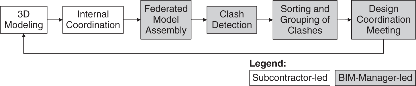
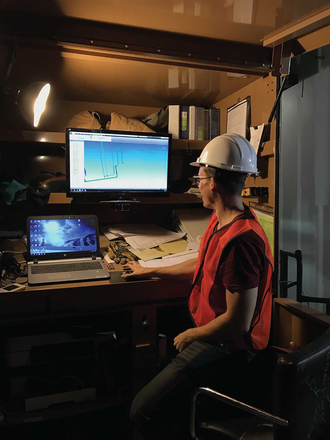
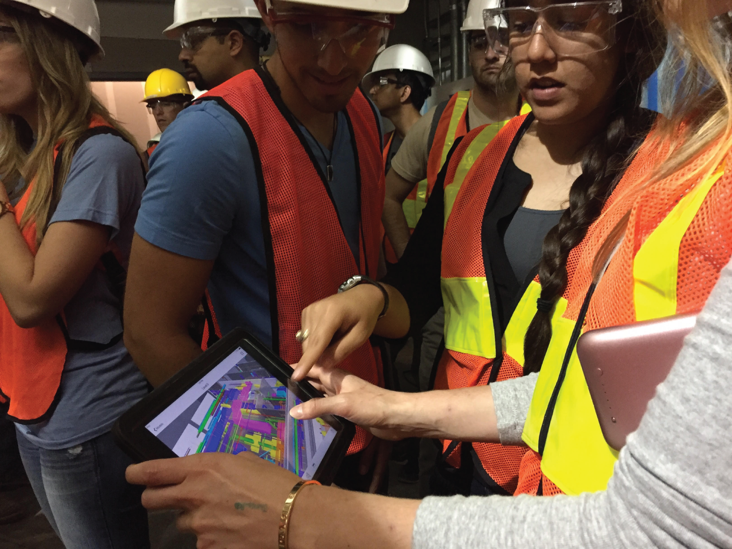
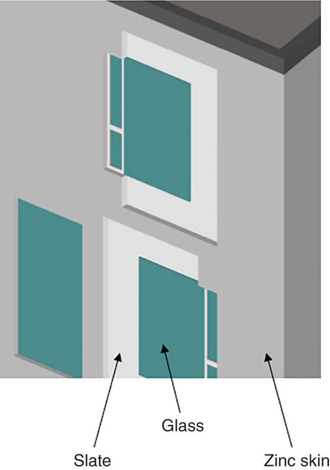
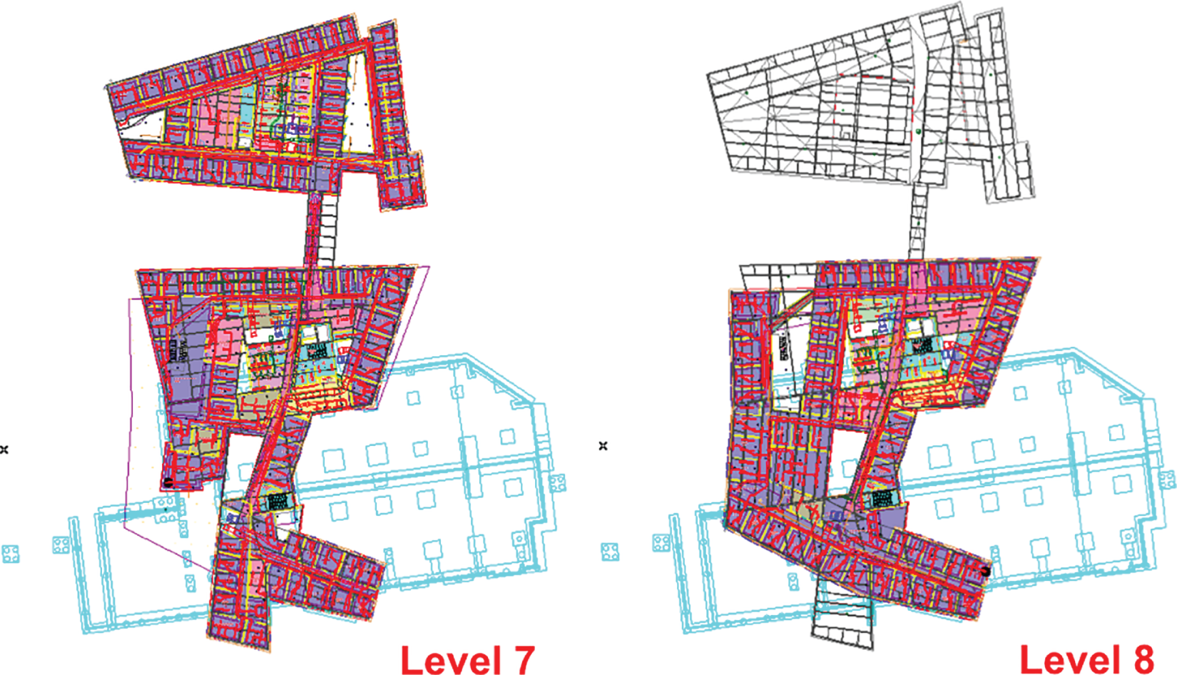
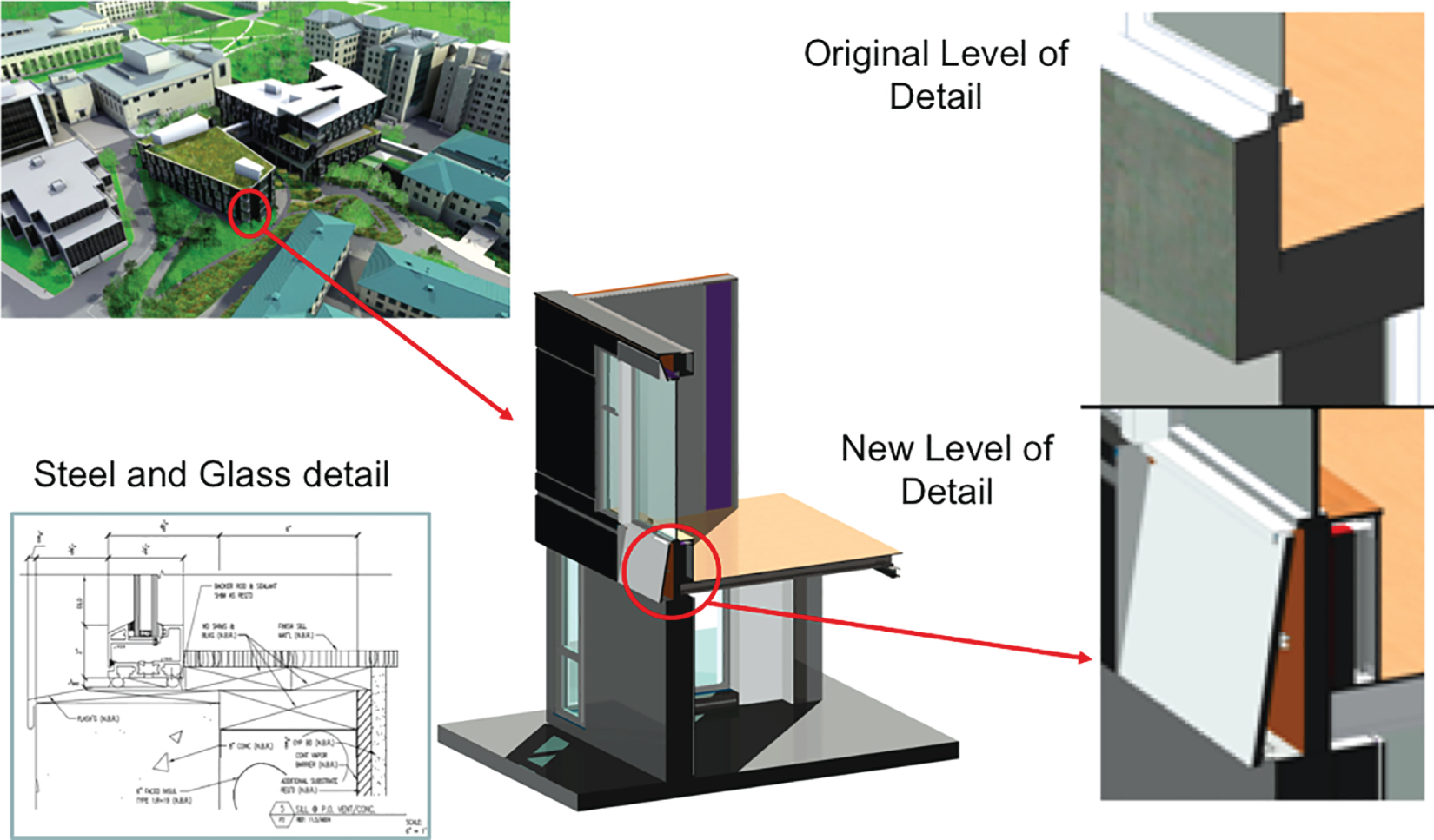
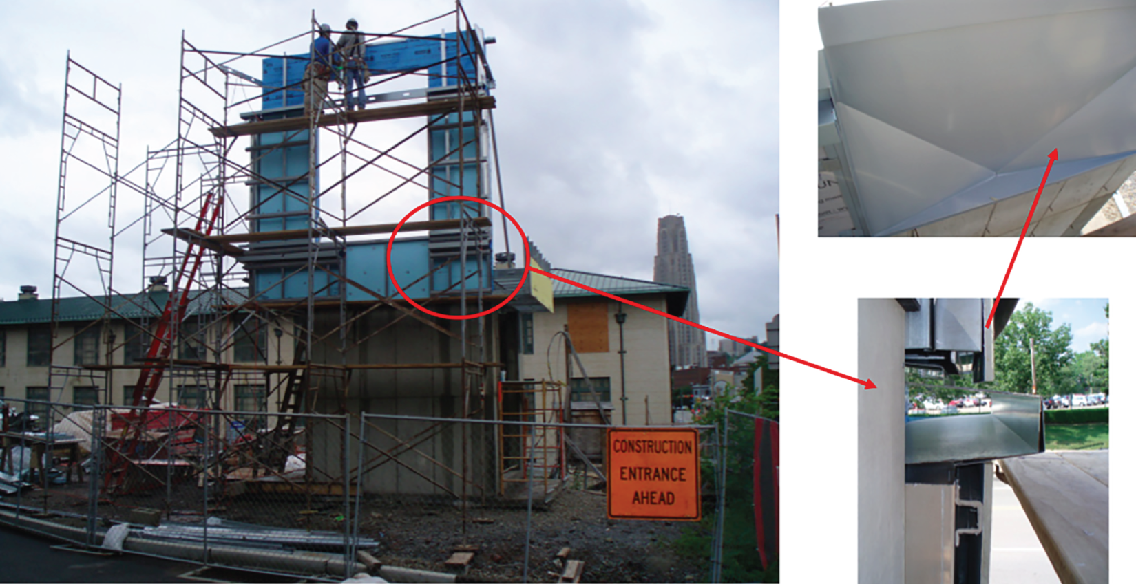
The process of coordinating designs involves first detailing a designer’s or engineer’s design into a fabrication model (i.e., LOD 400 model). The subcontractor’s development of a fabrication model is a translation in 3D of an engineer’s design, which aims at enabling efficient and cost-effective construction and installation of the design. Subcontractors and fabricators, hence, have the unique role of translating design intent into a clash-free and fabrication-ready model. This chapter covers specific guidelines for subcontractors and fabricators and discusses the roles and responsibilities of subcontractors and fabricators in the design coordination process. The chapter also describes how subcontractors and fabricators interface with other project teams. A case study of an exterior enclosure mockup for an academic building is presented and illustrates how subcontractors of various types, not only mechanical, electrical, plumbing, and fire protection (MEPF), can leverage virtual design and construction (VDC) to minimize issues in the field. Traditionally, mechanical, electrical, plumbing, and fire protection (MEPF) subcontractors would commence their work once they received design drawings and specifications from a project’s engineer(s). The information in the engineers’ drawings was augmented and detailed by the subcontractors, with development of shop drawings and details needed for installation, ensuring that the engineer’s design intent and prescribed system performance were maintained. Draftspersons employed by MEPF subcontractors typically had many years of field experience and approached the design coordination process with the tools they had at hand: 2D drawings and a light table. The objective was simple: avoid clashes in the field. Experienced draftspersons resolved many clashes in 2D; however, as pointed out in a study by Leite et al. (2011) and described in chapter 3, many clashes were missed due to human cognitive limitations of trying to visualize clashes in 3D when they were only represented in 2D. The 2D process was also very time consuming and iterative. Although some subcontractors were ahead of the curve and already using some form of 3D spatial coordination in the mid-1990s, the majority began using 3D spatial coordination with the wider adoption of BIM in the mid-2000s. It is worth noting that BIM models contain much more information than the 3D models used in the 1990s and early 2000s. Early 3D models were able to describe the shape, size, and location of MEPF system components. BIM, on the other hand, can also represent attribute data, such as building materials, equipment manufacturer, model or product identification codes, and maintenance information, as illustrated in Figure 7.1. Most importantly, being information-rich, building information models have enabled design coordination to begin at an earlier stage of the project. Although design coordination is a collaborative process between multiple project stakeholders (e.g., owner, designers, general contractor, and subcontractors), the process of coordinating designs involves first detailing an engineer’s design into a fabrication model (i.e., LOD 400). It is important to note that an MEPF subcontractor’s development of a fabrication model is not a design service. Rather, it is a reflection in 3D of an engineer’s design, which aims at enabling efficient and cost-effective construction and installation of the engineer’s design. In other words, engineers remain responsible for design, and contractors and subcontractors remain responsible for construction and installation. Subcontractors and fabricators, hence, have the unique role of translating design intent into a clash-free and fabrication-ready model. If we re-examine one of the figures shown in chapter 4 (now Figure 7.2), we can see that the subcontractor has an important role in ensuring the efficiency of the design coordination process as a whole, as the starting point in the process. In order to accomplish this, subcontractors need to ensure that their representatives in the design coordination process have both technical skills in the form of 3D modeling, as well as social skills, as they will need to work with a broad range of personality types and experience levels. For example, a GC may assign a young tech-savvy but inexperienced professional as their VDC coordinator. Other subcontractors may have minimal 3D modeling experience, but you will still need to coordinate with their model. FIGURE 7.1 Sample pipe model attributes Source: Image courtesy Hensel Phelps FIGURE 7.2 Design coordination workflow Before any subcontractors are signed to a project, the use of BIM should be stipulated in contract language. Each subcontractor should be required to abide by the BIM-related processes described in the project’s BIM project execution plan (PxP) to ensure successful design coordination. (See chapter 2 for more on the BIM PxP.) Each subcontractor should employ a 3D/BIM technician and/or respective lead project manager who will attend design coordination sessions and be responsible for resolving all model conflicts. After each design coordination session, the BIM technician implements the changes discussed in the model. Often, subcontractors implement changes during the design coordination sessions as well. Either way, each subcontractor should ensure that the model is updated for the next design coordination session and the design changes are communicated for construction execution. Table 7.1 illustrates sample roles and responsibilities of subcontractors, which can be included in a BIM PxP. The specific responsibilities of subcontractors shown in Table 7.1 are further detailed subsequently. Assuming the base model (i.e., structural and architectural) is available in at least level of development (LOD) 300, the subcontractor will develop a 3D model for their individual scope of work (e.g., mechanical, electrical, plumbing, or fire protection). Subcontractors can use various model-authoring software systems, as long as they are in compliance with the established guidelines in the project’s BIM PxP). If design coordination is being carried out in Autodesk Navisworks Manage®, for example, then the model-authoring software system should be able to export a file that that is readable in Navisworks® while maintaining geometry, naming conventions, and color coding. As discussed in chapters 3 and 4, before handing over their individual models to the BIM manager, subcontractors should perform internal (intradisciplinary) model coordination, ensuring that their models are clash free for their own scope of work as well as with the base model. Internal coordination can be performed through visual walkthroughs of the model as well as clash detection utilizing software such as Autodesk Navisworks Manage® or Solibri Model Checker. Subcontractors should also verify that there are no duplicates or overlapping elements in their model, that they are in the correct location, and that model elements follow BIM PxP naming and color-coding convention. TABLE 7.1 Sample subcontractor roles and responsibilities established in a BIM PxP Each subcontractor should employ a 3D/BIM technician and/or respective lead project manager who will attend design coordination sessions and be responsible for resolving all model conflicts. This person can also be responsible for 3D model generation. It is important to note that each subcontractor should be required to abide by the BIM-related processes described in the project’s BIM PxP to ensure successful design coordination. Subcontractors are responsible for resolving conflicts and fully coordinating their respective models with all applicable parties. This should take place in the design coordination sessions, with coordination by the GC’s BIM manager. In the event resolution between subcontractors is not obtained; the GC’s BIM manager will determine the necessary corrective action. After each design coordination session, the subcontractor’s BIM technician ensures that any design changes discussed are reflected in the model. The technician can implement these changes in the model during or after the design coordination session. The key is that the model needs to be up-to-date prior to subsequent coordination session and any changes that impact construction execution need to be communicated in a timely manner. After design coordination is complete and the federated 3D model is clash-free, the subcontractor should generate shop drawings from the coordinated model. Shop drawings are usually required for prefabricated components, which is the case for MEPF, but can also include structural steel, precast concrete, building skin, and many other components. Shop drawings are typically more detailed than construction drawings, as they illustrate fabrication and/or installation of components to field crews. Components in shop drawings are tagged and should match tagging used in the physical elements, to ensure effective field installation. They show complete dimensions, both horizontal and vertical, of components, routing of MEPF systems, structural framing, ceilings, partitions, equipment, lights, and other systems the project may have. Impacts caused by subcontractors’ installation of work that varies from the coordinated model (or has not been modeled) will be assessed by the GC’s BIM manager to determine corrective measures in mitigating said impacts. Subcontractors responsible for incorrectly installed work will bear the costs (should they occur) of remediating the impacted area. Hence, it is recommended that subcontractors install work strictly based on a coordinated model. In order to facilitate this, many subcontractors use a BIM station near their work face at the jobsite, as illustrated in Figure 7.3, where they can quickly refer to models and shop drawings while installing work. Others use tablet devices, as shown in Figure 7.4. Some are also experimenting with more innovative visualization approaches, including virtual, augmented, and mixed reality. Subcontractors interface with several project teams, including GCs, other subcontractors, designers, and the owner. The main BIM-related interface points are discussed in the following sections. FIGURE 7.3 Subcontractor BIM station near the work face FIGURE 7.4 Access of a coordinated model in the field via a tablet computer The GC has an important role in ensuring the efficiency of the design coordination process as a whole, leading most of the process. A GC’s BIM manager develops the project’s BIM PxP, which outlines the BIM-related processes and procedures, especially with regard to design coordination, and should be approved by the owner. The GC’s BIM manager is responsible for tailoring the plan to meet the owner’s and project’s requirements. This plan will then become the guiding document for all BIM-related processes and issues during the entire construction phase. At the start of the project, the GC usually sets up a meeting with all subcontractors, clearly describing expectations and priorities related to BIM in the project. During project execution, the GC moderates the design coordination sessions (usually on a weekly basis), manages subcontractor record modeling and deliverables, and manages file-sharing/coordination software. The GC also relays requests for information (RFIs) from subcontractors and/or other designers to the designer, to ensure that their design intent is maintained during the design coordination process. Due to the RFIs, necessary changes may have to be made in the design; designers respond to the RFIs with approval/disapproval for the requests for changes. Any design changes need to be reflected in the base model. All subcontractors should follow model development and submission requirements established in the BIM PxP. During project execution, the subcontractors interact with each other in moderated design coordination sessions (usually on a weekly basis). RFIs are issued through the GC. Each subcontractor should employ a 3D/BIM technician and/or respective lead project managers who attend design coordination sessions and are responsible for resolving all model conflicts. Subcontractors may have varying 3D modeling experience, but all will need to integrate their models into a federated model for design coordination purposes. After each design coordination session, the BIM technician implements the changes discussed in the model. Often, subcontractors implement changes during the design coordination sessions as well. Either way, each subcontractor should ensure that the model is updated for the next design coordination session and the design changes are communicated for construction execution. If the owner chooses to have the design team also develop a BIM PxP, the GC should make an effort for its BIM PxP to align with that of the design team, assuming a delivery method in which the owner has separate contracts with designer and GC. The subcontractors commence their work once they receive design drawings and specifications from the project’s architect(s) and/or engineer(s). The information in the designer’s drawings is augmented and detailed by the subcontractors, with development of shop drawings and details needed for installation, ensuring that the engineer’s design intent and prescribed system performance are maintained. The GC may relay RFIs from subcontractors and/or other designers to the designer, to ensure that their design intent is maintained during the design coordination process. In setting up a project for successful BIM-based design coordination, owners have the key role of setting the ground rules in terms of project requirements to GC and designers that will then trickle down to subcontractors. Owner requirements should be clearly stated in contract language with the GC and reflected in the BIM PxP. Ensuring the development of a detailed BIM PxP will also set up a framework for the project team in terms of expectations of BIM use in the project, including modeling requirements, file-sharing protocols, and team composition. Project 2 was an academic building consisting of two buildings and an underground garage with 150 spaces. The two buildings included about 210,000 square feet of area. The total project cost was $97 million (in U.S. dollars), and the construction cost was estimated at $72 million. The construction for Project 2 was completed in 2009. This case study project began in the first decade in which BIM was beginning to see widespread implementation in the United States, when many GCs were beginning to implement BIM in pilot projects. This was such a case. The GC did not have in-house BIM experience and, hence, hired a third party to develop the project BIM based on 2D drawings and specifications provided by the designers. Ideally, the model should have been developed and augmented since the early design stages, in order to help the design team better understand the project and build the facility virtually. The approach carried out in Project 2, however, led to reentering of data. The third-party modelers delivered the first version of the building information model from 85% complete 2D architectural, structural, and MEPF drawings. The MEPF included all elements larger than 1.5”. When construction for the building’s underground garage was being carried out, the GC received a new BIM, based on 100% complete drawings. By this time, the heating, plumbing, fire safety, electrical, and sheet metal subcontractors had started their weekly coordination meetings. Even though they had a building information model at hand, the subcontractors decided to coordinate their designs by overlaying 2D drawings on a light table, since most of the subcontractors did not design in 3D at the time this research was being carried out. Furthermore, the subcontractors argued that there were no BIM requirements in their contract. All coordination was done on 2D drawings. Given the fact that subcontractors were going to coordinate in 2D and that there was a MEPF model available, this became one of the motivations of the research in Leite et al. (2011): to investigate the needed LOD in a building information model for MEPF design coordination. The study by Leite et al. (2011) is unique as it is one of the few that compares the performance of BIM-based design coordination and 2D-based design coordination for a real-world project. The GC also gave the building information model to the exterior enclosure subcontractor, who concluded that the LOD in the model was not sufficient to analyze the constructability of the building’s skin. The LOD of the model that the GC provided to this subcontractor had no connections represented. According to the exterior enclosure subcontractor, these connections were fundamental to assess how they would build the skin, considering that there were many unique layers in the exterior enclosure and many variations of windows in this project. Thus, Project 2 motivated two distinct analyses. The first was related to the modeling effort based on the number of objects that needed to be modeled and the associated time for modeling of the components in different LODs. In order to obtain comparable modeling times, the research team developed two models of a section of Project 2’s exterior enclosure: one in the original LOD, found in the third-party model, and the other in the fabrication LOD, according to requirements specified by the exterior enclosure subcontractor. The second analysis was on the differences in the accuracy and comprehensiveness of the clashes that were detected by performing automatic clash detection using a building information model and manual clash detection (i.e., with a light table using 2D drawing overlays). The automatic clash detection was carried out by the research team, and the manual coordination was carried out by the project subcontractors with one researcher present collecting data on clashes identified during coordination meetings. Chapter 3 discusses in detail the results of the analyses carried out in Project 2. For this chapter, the focus will be on a unique aspect of the first analysis, which leveraged BIM for the exterior enclosure mockup. Project 2 had a unique exterior enclosure design, which was what prompted the development of an exterior enclosure mockup. The building skin was composed of several materials, assembled in different formations, as illustrated in Figure 7.5. Also, no two floor plans were the same, as illustrated in Figure 7.6 with floor plans for levels seven and eight. Due to these unique project characteristics, the GC thought the exterior enclosure subcontractor would benefit from having access to the BIM model, and hence shared it with them. The exterior enclosure subcontractor, after analyzing the model, concluded that the LOD in the model was not sufficient to analyze the constructability of the building’s skin. The original model was in LOD 300, with no connections represented, as shown in Figure 7.7 (original LOD). According to the exterior enclosure subcontractor, these connections were fundamental to assess how they would build the skin, considering that there were many unique layers in the exterior enclosure and many variations of windows in this project. The GC then decided to create a model in LOD 400, with all the connection details of a portion of Project 2’s exterior enclosure that the subcontractor needed (new LOD in Figure 7.7), so they could study how to build the building skin. Specifically, the model contained metal studs, interior gypsum, wood framing, Z-channels, batt insulation, rigid insulation, hat channels, flashing, cement/aluminum panels, zinc sheeting, zinc window surrounds, windows, and curtain walls, resulting in 240 objects in total. FIGURE 7.5 Diverse materials and varying geometry in exterior enclosure design FIGURE 7.6 Each floor with a unique geometry FIGURE 7.7 Exterior enclosure mockup model The LOD 400 model was then used by the exterior enclosure subcontractor to build a full-scale physical prototype of the exterior enclosure on site, test out the various connection details and waterproofing, as well as assess construction productivity rates to associated activities. Figure 7.8 shows a crew working on the mockup assembly, and details of the zinc building skin and connections. The research team took the opportunity of having both versions of the same model to carry out the LOD modeling effort analysis, described in Leite et al. (2011) and in chapter 3. While modeling both versions, the time spent to model each type of component was recorded. Also, the number of objects in the two versions of the model was recorded. The LOD 400 model was compared against the LOD 300 model, which was equivalent to the LOD in the complete version of Project 2’s BIM (developed by a third party). FIGURE 7.8 Exterior enclosure mockup assembly For Project 2, the research team compared two versions of the same section of the building, modeled for different purposes. The first version, which consisted of a precise LOD model that was created for visualization purposes, took 3 hours to model, including the time taken to understand the 2D drawings provided by the project engineer. This version contained a total of 12 objects, which included walls, slabs, and windows, modeled as single objects. The LOD 400 version of this model, which was created mainly for the exterior subcontractor to study the connections, took 34 hours to model (11.3× the LOD 300 model). This version contained a total of 240 objects, including parts and connections of walls, slabs, and windows. The results for Project 2 show that the increase in the LOD requires less modeling time per object. The exterior enclosure subcontractor claimed that having access to the LOD 400 model helped them clearly visualize and understand their scope of work, identifying parts needed to simulate its physical fabrication. The LOD 400 model served as a VDC evaluation without the initial cost of the physical construction of the mockup. It was particularly beneficial in this case as it was used early in the design phase through to fabrication and construction sequencing. The exterior enclosure subcontractor was able to develop fabrication specifications, performance compliance, and assembly and installation procedures. The goal was to identify any constructability issues and improve productively for the assembly of the actual building skin. The early constructability analysis also prevented issues in the field, which could have potentially caused further delays in a project that was already trying to find ways to catch up on its schedule from early project delays. This chapter outlined specific guidelines for subcontractors and fabricators and discussed the roles and responsibilities of subcontractors and fabricators in the design coordination process. The chapter also described how subcontractors and fabricators interface with other project teams, including GCs, designers, owners, and other subcontractors. A case study of an exterior enclosure mockup for an academic building was presented and illustrates how subcontractors of various types, not only MEPF, can leverage VDC to minimize issues in the field.
Chapter 7
Specific Guidelines for Subcontractors and Fabricators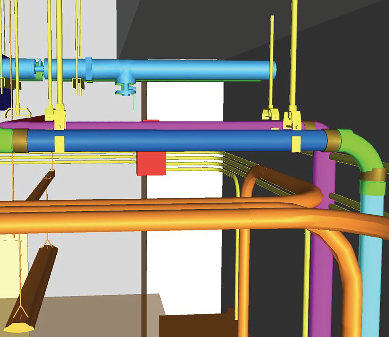
7.0 Executive Summary
7.1 Introduction
7.2 Role of Subcontractors and Fabricators in the Design Coordination Process
7.2.1 Generating the Respective Trade Model
BIM-related role
BIM-related responsibility
BIM technician
7.2.2 Attending Weekly Design Coordination Sessions and Following Model Development and Submission Requirements Established in the BIM PxP
7.2.3 Ensuring Comprehensive Model Coordination between Trades
7.2.4 Updating the Model During the Construction Phase
7.2.5 Producing Shop Drawings from the Coordinated Model
7.2.6 Installing Work Based on the Coordinated Construction Model
7.3 Interfacing with Other Stakeholders
7.3.1 General Contractor
7.3.2 Other Subcontractors
7.3.3 Designers
7.3.4 Owner
7.4 Case Study: Academic Building
7.5 Summary and Discussion Points
Reference
Note