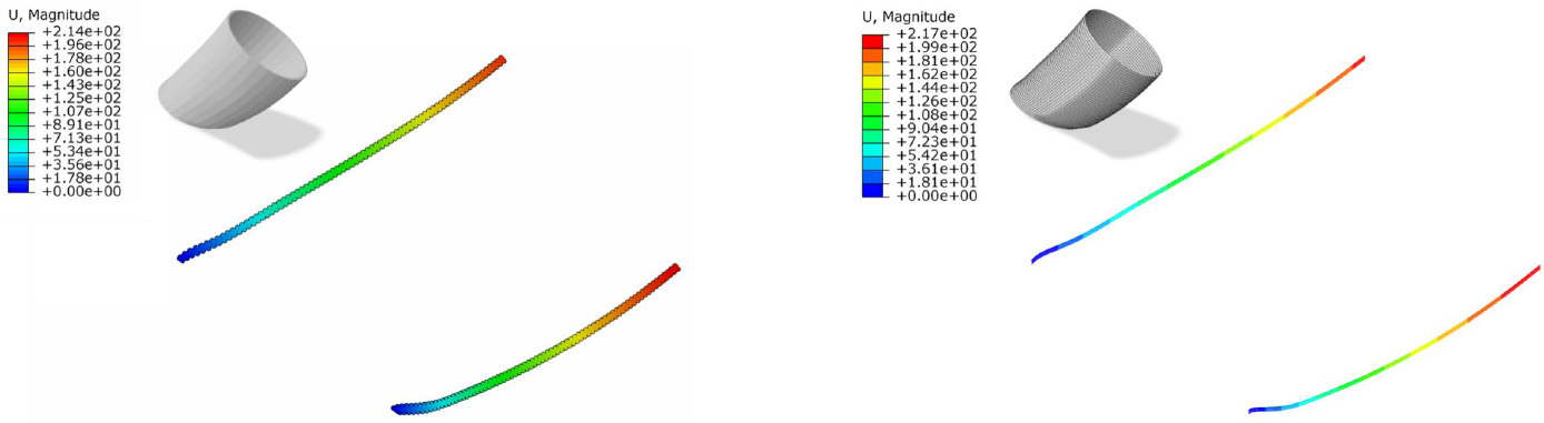
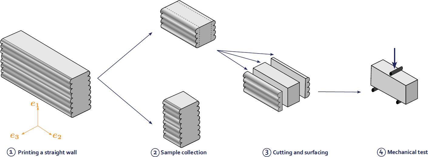
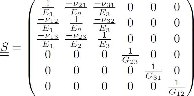
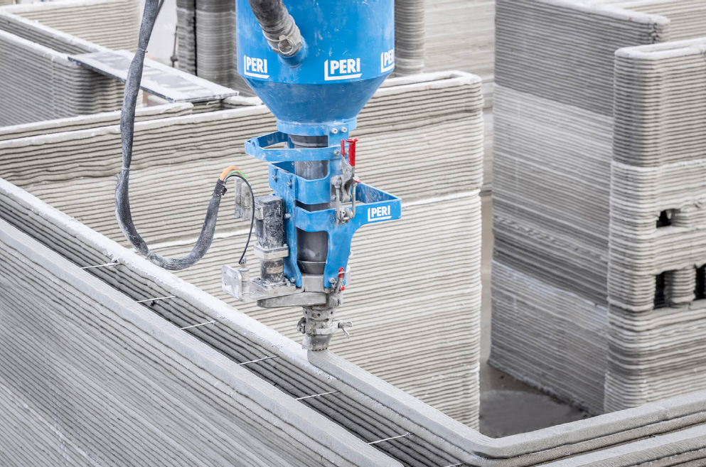
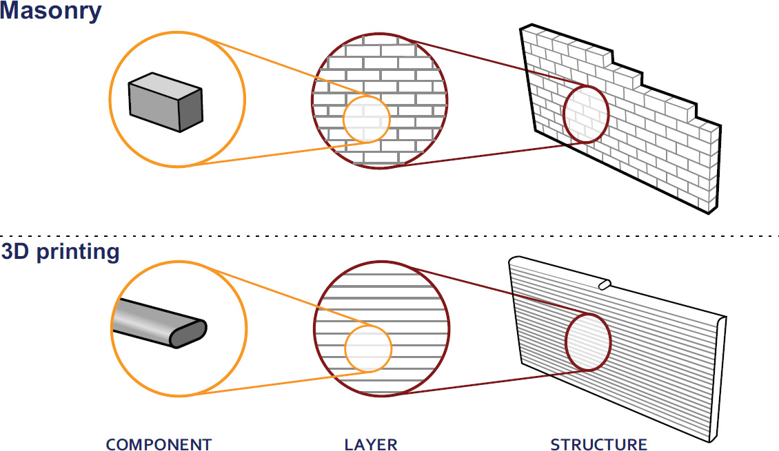
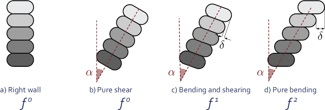
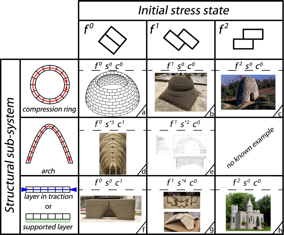
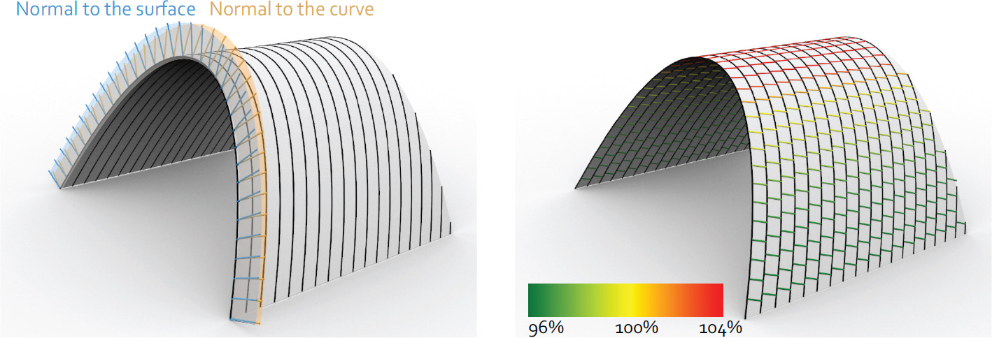
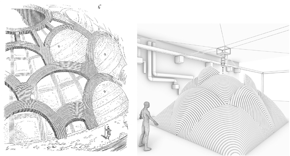
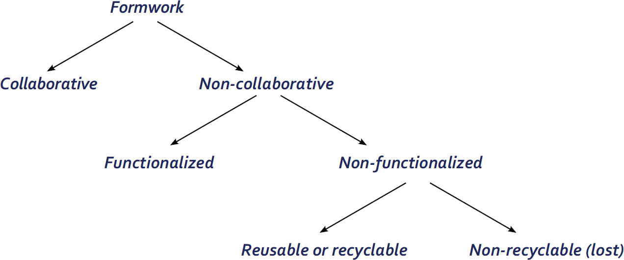
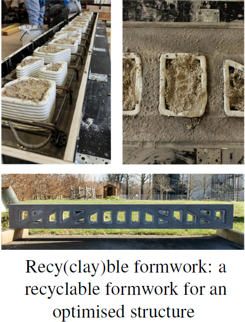
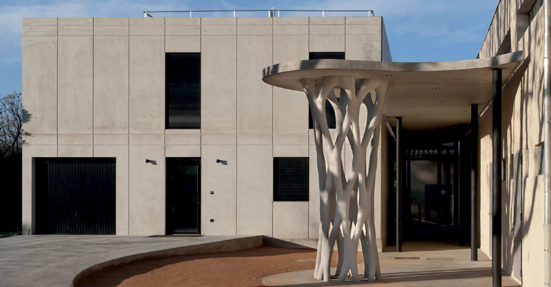
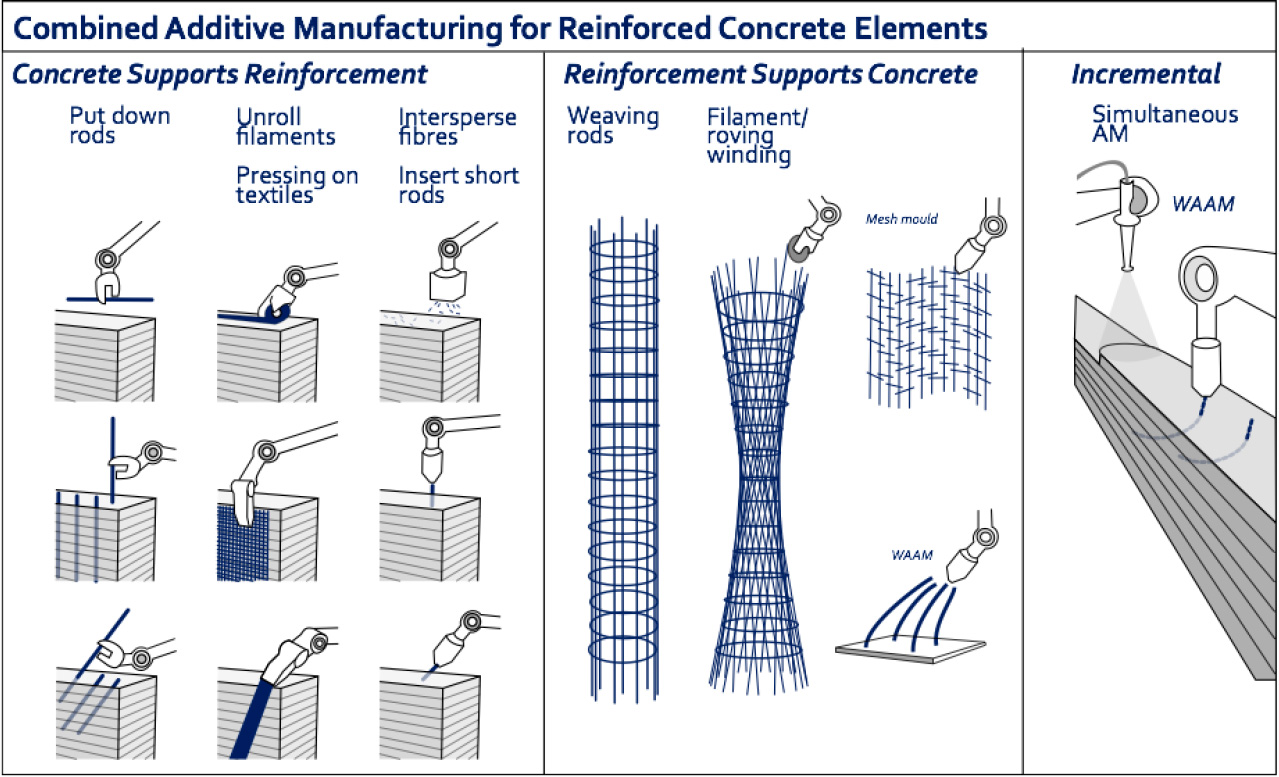
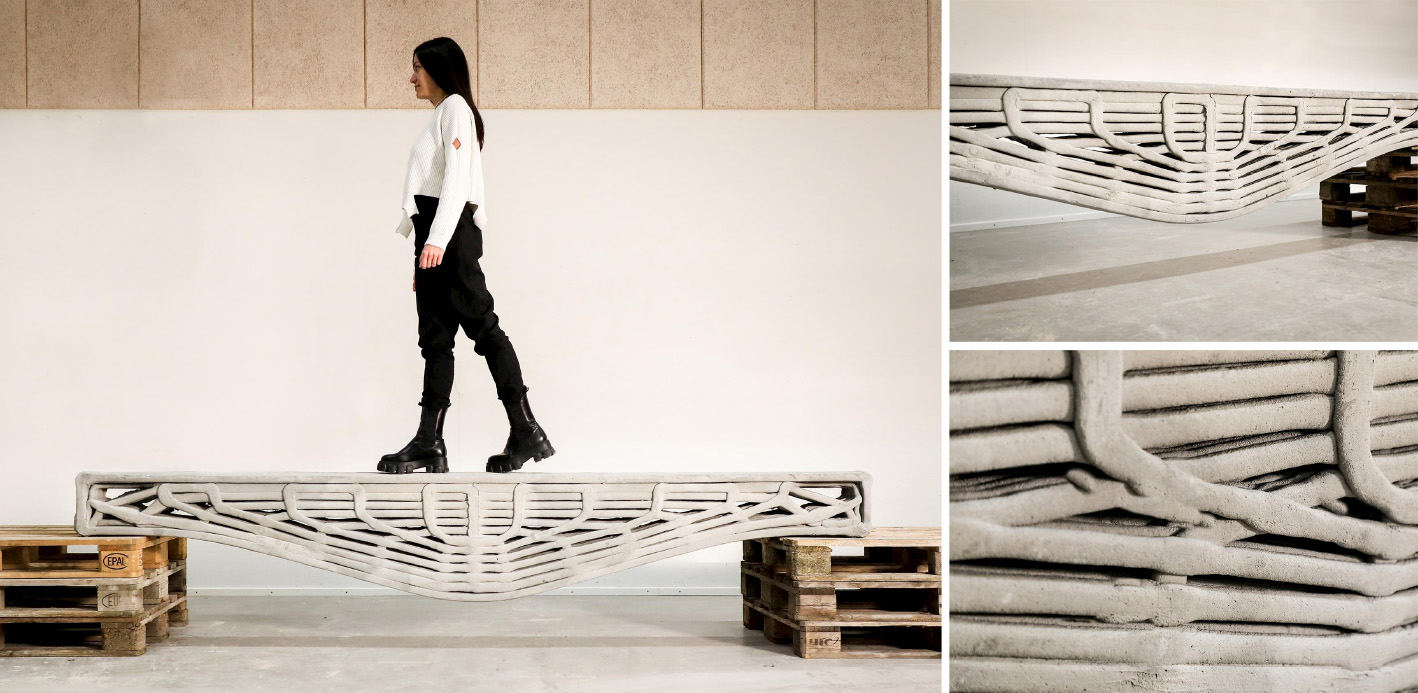
Romain MESNIL1, Romain DUBALLET2 and Olivier BAVEREL1 1 Laboratoire Navier, École des Ponts, Marne-la-Vallée, France 2 XTreeE, Rungis, France Construction materials are responsible for over 7% of man-made greenhouse gas emissions and account for almost half of humanity’s use of raw materials. Structural designers are therefore obliged to couple material savings with the safety of users of future infrastructures (Baverel et al. 2022). René Motro has identified five structural design levers available to engineers and architects in a design approach known as structural morphology: In the case of 3D concrete printing, concrete remains a material that performs well in compression and poorly in tension, whatever the chosen material mix-design. This leaves engineers with the forces, the technology, the structure and the shape. The latter is an obvious lever for structural optimization, since it is well known that an arch uses the material much more efficiently than a beam in bending. 3D printing offers greater formal freedom than traditional construction processes, and therefore seems to lead to more economical designs in terms of building materials. However, this intuition is largely just a promise yet to be fulfilled. The notion of arrangement between components with hierarchical relationships remains essential to design structures and makes them readable. This compositional work remains relatively in the background of current 3D printing research. However, it is one of the key issues in the effective deployment of this technology and has historically been a difficult barrier to overcome. It is interesting to note that modern building materials have led to structural systems that benefit the most from their mechanical properties. Early metal structures, such as the Iron Bridge designed by Thomas Farnolls Pritchard in 1779 are based on the vocabulary of masonry structures, while the truss bridges built by Gustave Eiffel take advantage of metal’s excellent tensile strength. Similarly, the use of prestressing enabled Eugène Freyssinet to take advantage of concrete’s high compressive strength more than a century after Vicat created modern concretes in 1817. More recently, composite materials, which are characterized by high deformation at failure, have led to explorations of elastic gridshells, several decades after their creation (Caron et al. 2018). Figure 5.1. Evolution of the structural morphology of steel bridges These few examples illustrate the need to consider the construction system in conjunction with the technology used to shape the material. It is thus likely that truly relevant printed structures will not be simple adaptations of traditional reinforced concrete structures. The difficulty of this approach becomes clear when we consider the time it takes from the creation of a material (or process) to the construction of structural masterpieces that synthesize all the dimensions of structural morphology. Engineering is the art of shaping materials we do not fully understand, into forms we cannot accurately analyze in order to withstand forces we cannot properly assess, in such a way that the public has no reason to suspect the extent of our ignorance. This definition by Archie R. Dykes, in a speech to the British Institution of Structural Engineers in 1976, shows that structural engineers have to design under uncertainty. A probability-based approach to design was developed in the second half of the 20th century, then formalized, notably with the Eurocodes. The Eurocodes dimensioning approach is based on the principle of limit states and distinguishes between two categories: The loads applied to the structure (self-weight G, wind W , snow S, temperature T and operating loads Q) are calculated on the basis of an estimated building life (typically 50 years). These loads are then combined, bearing in mind that the combination of several simultaneous loads is rarer than the occurrence of a single one. Of course, self-weight is always taken into account in load combinations. The loads qELU applied at the ULS are greater than the loads applied at the SLS qELS: we accept a loss of building functionality for these loads, which have a very rare probability of occurrence in the liftetime of a structure. The design strength of the material is a function of the characteristic strength fk, which is the strength at the 5th percentile, and the material’s partial safety coefficient γm. In the case of concrete, γm = 1.5. Note that two materials with the same mean strength value do not necessarily have the same characteristic value and therefore the same design strength. This is illustrated in Figure 5.2, which shows the probability densities for the failure stress of two materials. Although the mean strength is the same, material 2 (shown in ochre) has a higher characteristic strength thanks to less scatter in the results. Figure 5.2. Two materials with the same average strength, but different design strengths The principle of ULS design is illustrated in Figure 5.3. It shows two probability densities of stress level and material strength, weighted by safety coefficients. Figure 5.3. Principle of Eurocode ultimate limit state design: a probable stress level is compared with the material’s design strength The other main principle of the codes is ductility: we want to be able to observe disorders before a building totally (or partially) collapses. Concrete is brittle in tension, but pseudo-ductile in compression. Three main strategies have been developed to overcome this brittleness: The design of printed concrete structures will therefore have to fit into a framework of standards that is already well established. The tests will have to be easily reproducible by economic actors, and a certain ductility will have to be demonstrated. Concrete 3D printing needs to move toward structural applications to have a significant impact on the construction industry and this is the thrust of research work being carried out in several laboratories (Asprone et al. 2018; Marchment and Sanjayan 2020; Caron et al. 2021). Historical analysis shows that shapes and structures evolve with the technologies and materials available. For printed concrete structures, this evolution is not yet set in stone. The aim of this chapter is therefore to provide an overview of the potential structural applications of printed concrete. First, it identifies mechanical models for printed structures and methods for assessing the mechanical properties of the hardened material. Second, this section presents ways of assessing the material properties required for the dimensioning process and suggests ways in which printed structures can be modeled efficiently. Once equipped with the right physical models, the engineer can explore the various dimensions of structural morphology. The third section discusses the application of printing as masonry, that is, without reinforcement, with a focus on the question of form and structure. The fourth section briefly presents applications of 3D printing in structures reinforced with reinforcement or fibers, with a focus on technology. The fifth section presents applications using prestressing and explores the strength dimension of structural morphology. The chapter concludes with a discussion of modeling and optimization tools that could be used to assist engineers in their design approach. One of the first questions for an engineer calculating a structure is which model to adopt to capture the correct physical phenomena at play, and which tests to carry out to apply this model in practice. Although a volume at stake can provide accurate results, it is cumbersome and costly to implement in practice, and more difficult to interpret than a simpler model (plate or beam). Given the slenderness of the printed walls, a plate model seems more suitable, as it is compatible with structural design tools and the structural engineer’s vocabulary. An immediate difficulty then arises: a 3D-printed structure has several scales to consider – that of the material, of the structure, but also that of the bead. Indeed, bead geometry can influence stress distribution in the shell. A recent study has shown that the geometry of the filaments after deposition has a significant influence on the stiffness of the structure, particularly for bending deformations (Mesnil et al. 2023). Figure 5.4 illustrates the distribution of principal stresses in a section composed of four layers subjected to uniform loading. The geometry of the filaments is inspired by the oblong model proposed by Carneau et al. (2022). We find that the major stresses have a very complex distribution, where a test on a plate of uniform thickness would have led to zero major stress and constant minor stress. Figure 5.4. Principal stress distributions in a printed cord under uniform load in linear elasticity This simple example shows that a test on a printed specimen with the protuberances resulting from printing is indeed a test of structure and not of material. This meso-structure is consubstantial with the 3D extrusion printing process. It should also be noted that, in addition to geometric heterogeneity, it is also possible to have material heterogeneity, which affects the stress distribution in a printed surface. Characterization of the printed material is therefore not necessarily the most relevant approach for obtaining input parameters for a structural calculation. Tests on specimens printed with the real meso-structure raise new issues. For example, the width of a printed bead depends on the printing process and may differ from usual specimen widths (e.g. 40 mm for a flexural specimen for mortar). The preparation of non-rectified specimens also raises problems for test implementation due to the brittleness of the concrete. A simpler approach than experimental characterization of the micro-structure may be to test the material properties, on the one hand, and to take into account the effect of the micro-structure by an appropriate model. Thus, it has been shown that the elastic behavior of printed structures can be described by a Kirchoff–Love plate model, with a stiffness matrix calculated by periodic homogenization (Mesnil et al. 2023). The results show that the components of this matrix are not reducible to an equivalent Young’s modulus or thickness, as flexural and membrane behavior are very different. Figure 5.5 shows a comparison between a calculation with volume elements and a calculation with an equivalent plate model. The difference in deflection is of the order of 2%, with the number of vertices divided by 1,000 for the plate model. Figure 5.5. Visualization of the deformation of an inclined cylinder with a volume model and an equivalent plate model (image: Mesnil et al. (2023)) The advantage of this homogenization method is not only a considerable computational gain over finite volume elements, but also a better understanding of overall behavior, thanks to the use of generalized stresses and strains. In this way, the study carried out separates the influence of the material, on the one hand, and the geometry of the layers, on the other hand. Taking account of heterogeneities in the stiffness and strength of printed structures is a recent research topic, but the characterization of printed material on geometries without asperities seems to be preferred at the moment, as it frees us from experimental complications, and enables us to transfer the know-how developed on mortar characterization. It is possible to characterize a cast material, an extruded material using laboratory equipment, or an extruded material using industrial equipment. The relative merits of the three approaches are compared in a recent publication, which serves as the basis for an international research collaboration1 (Mechtcherine et al. 2022). While the test on cast material may yield interesting results at first glance, the influence of the process on the properties of the hardened material cannot be ignored a priori. Factors of influence include drying, mixing quality and possibly the dispersion of the setting accelerator in two-component systems. Figure 5.6 illustrates a protocol for characterizing a printed material using this methodology: Figure 5.6. Protocol for a printed material characterization test, the printing direction is the two-direction Structural engineers often assume that concrete is an isotropic material, with the same stiffness and strength properties regardless of the direction of loading. This assumption is not a priori directly applicable to extrusion-printed concrete, as the method of deposition can influence the material’s micro-structure. Researchers have observed ellipsoidal pores elongated along the extrusion direction, as well as material orthotropy (van den Heever et al. 2022; Kruger and van der Westhuizen 2023). Therefore, a priori, we must use an orthotropic material model with three directions, the extrusion direction, denoted as 2 in Figure 5.6, the transverse direction 1, perpendicular to the extrusion direction but in the mean plane of the printed wall, and the direction 3, which is perpendicular to this plane. This potential orthotropy is the source of greater complexity in experimental characterization, which seems incompatible with practical applications. Elasticity theory tells us that an orthotropic material is characterized by nine material parameters, while an isotropic material is characterized by just two (e.g. Young’s modulus and Poisson’s ratio). Equation [5.2] gives the general form of the compliance matrix This theoretical number of parameters can be reduced in practice. Note that in many cases, 3D printing is used to produce thin-walled structures that can be modeled by plates. In such cases, the most suitable model is the plane stress model: σ13 = σ23 = σ33 = 0. The strength properties of the material in these load directions therefore generally do not need to be evaluated. Experiments show that Poisson’s ratios do appear to vary with direction (Kruger and van der Westhuizen 2023), but this variation is small enough to be disregarded in practice, and the Poisson’s ratio of the cast material can be used. Table 5.1 summarizes the properties needed to describe an orthotropic material and the relevance of testing them in practice. Table 5.1. Summary of material properties to be evaluated The methodology outlined in Figure 5.6 shows that the mechanical tests carried out on printed material are identical to those performed on conventional hardened material. These include the following: Specimen dimensions vary according to maximum aggregate size. The dimensions specified in the standard must be respected, as concrete has a brittle fracture mode, and the measured value depends on the size of the specimen. In this respect, we refer to the work of Bažant (1999). In all cases, the experimenter must carry out sufficient tests to calculate characteristic values. The 3D printing process results in a mesostructure whose mechanical properties cannot be directly assimilated to quantities commonly used by engineers (Young’s modulus or Poisson’s ratio). We have presented an experimental method for identifying the parameters of the hardened material by preparing sawn and rectified specimens. Using the theory of periodic homogenization, it is then possible to derive a homogeneous plate stiffness, enabling engineers to perform calculations using models they are familiar with. However, models capable of describing the ruin of a periodic structure have not been applied to the microstructure resulting from concrete printing. This means that, for the time being, we have to make do with the strengths obtained from tests on rectified specimens, until we have a better understanding of the influence of microstructure on the potential failure mechanisms of printed concrete. Having addressed the question of the appropriate mechanical model, the remainder of this chapter will focus on the morphological strategies employed to build 3D-printed structures. With a view to the gradual adoption of 3D printing technologies by the industry, and although at first glance this solution is less relevant than reinforced concrete-type applications, 3D-printed structures can be designed according to Eurocode 6, that is, in masonry. There are two complementary approaches to masonry construction that differ in their strategy for placing ductile reinforcements: reinforced masonry and confined masonry. Reinforced masonry is a reinforcement strategy designed to place ductile elements, such as metal spacers and steel rebars, between the stacked elements of a masonry wall. It therefore implies intervention during the erection of the wall, which is quite natural for cinder block construction, but less so for 3D printing. In this case, either the process has to be interrupted to make way for human intervention, or the elements have to be placed during the printing process, either automatically or manually if the latter is slow enough to allow this. This strategy has been used extensively for on-site 3D printing experiments, whether or not they have been the subject of normative justification. Indeed, if we take the example of on-site printing of a single house, the characteristic times between each layer deposited are sufficiently high (on the order of tens of minutes) to allow intervention on areas not stressed by the machine during printing. It should also be noted that for a variety of reasons, such as the progressive strength increase of the material, inclement weather conditions, or simply maintenance, such printing may be interrupted for periods exceeding the setting time of the concrete, thus creating vertical discontinuities. Figure 5.7. Metal spacers on an on-site printed wall (image: Peri SE) Confined masonry consists of framing a wall of unreinforced material with chains, that is, longitudinal elements such as columns and beams, whose mechanical cohesion with the wall is ensured. The result is a pseudo-ductile object that can easily be used in buildings up to R+6. The advantage of this paradigm for large-scale 3D printing is that it shifts the question of reinforcement to the peripheral connections of a printed wall. A similar principle was adopted to certify the printed walls on the south facade of the five houses in the Villiaprint project in Reims, as shown in Figure 5.8, which obtained its first Appréciation Technique d’Expérimentation (ATEx) from the CSTB in 2020 for printed walls in cementitious materials. Here, printed walls without reinforcement act as infill between reinforced concrete columns supporting a wooden roof and connected at the top by a horizontal beam. The mechanical properties required of the walls are limited to impact resistance, in-plane bracing and waterproofing. Figure 5.8. South facade of a house in the Villiaprint project, 2022 (XtreeE) From a strictly environmental and mechanical point of view, such a principle can hardly claim optimal results, given the quantities of cement-rich material involved. Rather, the interest lies in the aspect of normative experimentation, health and safety in the industrial sector (the Villiaprint project as a whole was an experiment in off-site prefabrication), as well as architectural quality (the five houses, in a social housing context, all boast unique and attractive facades, and this for virtually no extra cost, given the robotic manufacturing method). Two areas remain to be explored: the use of “low-carbon” materials with a lower impact, and the use of structure to reduce the amount of materials used. Conventional printed walls, made of three layers of mortar, are no lighter than breeze-block walls, which partly explains the slow take-up of 3D printing technology for printing individual houses. Other structural systems therefore need to be explored if a substantial gain in mechanical performance is to be achieved. A mechanically optimized chain-linked masonry principle has been proposed by Duballet et al. (2019) on the basis of a spatial lattice. The idea is to replace a cinder block and mortar wall with a wall in which the mortar is printed in the form of a spatial lattice and separated by insulating blocks. A prototype on a representative scale has been produced (Duballet et al. 2020). Such a principle seems to be justified first and foremost by the considerable weight reduction it enables, compared with traditional construction systems (see Table 5.2). Table 5.2. Comparison of the performance of different chain-linked masonry systems One strategy for avoiding bending in structural elements is to introduce curvature. This strategy is ancient and has been widely used throughout history with materials that have low tensile strength to make arches, domes, vaults and cupolas. Formwork was often used to build the structure, which was then skillfully removed. The final shape was designed not to bend, but simply to be funicular, with only compressive stresses acting on the structure. Clever builders (Persians, Romans, Byzantines, Brunelleschi, etc.) have long found constructive strategies in stone or brick to create vaults without formwork, as Auguste Choisy reports in his reference work (Choisy 1883). It is possible to draw an analogy between the constructive arrangements specific to masonry and 3D printing, as shown in the work of Carneau et al. (2020) and Motamedi et al. (2022). In 3D printing, the filament replaces the brick (Figure 5.9), and the stacking of layers replaces that of brick or cut stone beds. In addition, the materials used are frictional materials with greater compressive strength than tensile strength. It is therefore possible to transfer construction techniques originally developed for masonry vaults to 3D printing, and thus dispense with formwork. However, this requires the structure to be in equilibrium with compressive forces at every stage of its construction. The stability of the printed structure can be assessed at both filament and structure level. Carneau proposes a classification of dispensing strategies, which are linked to the robotic system. The stability of the structure depends on the shape and the toolpath strategy adopted. When stacking filaments in 3D printing, there are three possible overhang scenarios (classified by Carneau as fi and illustrated in Figure 5.10): Figure 5.9. Analogy between masonry and 3D concrete printing, according to Carneau et al. (2020) Figure 5.10. Cord placement strategies according to Carneau et al. (2020) These strategies are also found in masonry structures, with ashlar masonry, Nubian vaults and corbelled domes. In addition to local filament stability, we can add the presence of intermediate supports, denoted by the superscript si, and layer continuity, denoted by the superscript ci. Carneau et al. (2020) associate these strategies with a classification that is linked to robotic complexity. Figure 5.11 shows examples of construction typologies depending on the layer deposition strategy, but also on the overall behavior of the structure: the first row corresponds to biaxial compression states, the second to arched behavior and the last row to functioning combining compression and tension. In the first column, the case of the barrel vault shows the advantage that 3D printing can have over masonry. With 3D printing, and the layer pressing strategy in particular, the cross-section of the layers can differ from a rectangular shape. Consequently, if the extrusion nozzle is always aligned with the surface, the contact area between one layer and the next is optimal and no local overhangs appear (Gosselin et al. 2016). In the second column, the 3D-printed dome shown in the table is the result of this behavior. The layers are printed orthogonally to the surface norm. The pure bending strategy in the right-hand column is difficult to apply to concrete 3D printing due to the low strength of the fresh material. For example, a layer laid horizontally but with a local overhang is very likely to over-deform. Figure 5.11. Examples of structure types according to printing mode (Carneau et al. 2020) The correlation between the brick’s initial stress state criterion and the ability to control the geometry of the extruded layer is straightforward. These two aspects can also be aligned with material properties. A layer printed with a material with a high initial yield strength (the case of infinite brick extrusion) takes the shape of the nozzle. This is the best choice when the layer has to withstand high initial stresses, such as bending moments caused by a local overhang: bending and shearing. On the other hand, extrusion with a very low initial yield strength (for example, with the Layer Pressing strategy) results in a layer capable of withstanding only a low shear stress when exiting the nozzle. However, it does offer the possibility of modifying its cross-sectional geometry. This relationship between material properties, initial stress state and control of layer geometry is illustrated in Figure 5.11. We have just seen that the rheological strategy employed has a direct impact on the cantilever layer deposition strategy. The analogy with masonry allows to extrapolate more complex morphological strategies than the simple superposition of a few layers. The construction of certain vaults without arches requires a special layout. For example, a barrel vault can only be stable without intermediate support if the brick bed is not arranged along the meridians (configuration f0s∗2c0). Figure 5.12 shows an example of such a strategy, known as Nubian vaulting, where the brick beds (or print beads) are contained in a plane, making an angle of 24° with the vertical. It can clearly be seen that there is a variable angle between the normal to the surface (blue lines) and the plane containing the curve (orange lines), but also with the vertical direction. There is thus a torsion of the brick bed or layer. Such twisting is difficult to achieve manually and requires a six-axis robot instead of traditional systems. Here, the robot demonstrates its advantages over the human hand in terms of accuracy and speed. Figure 5.12. Nubian vault. Left: inclination of bead plane (orange) and surface normal (blue). Right: relative distance between layers In addition, the distance between the curves drawn on the surface is variable. In practice, this means that printing along these lines results in crushing of the printed filaments. Rheological strategies based on a very significant evolution of the shear yield stress over time, typical of two-component approaches, can be exploited to achieve significant layer thickness variations, and therefore a more developed formal language. However, the crushing force due to layer thickness variation must be taken into account in the stability of the structure (Carneau et al. 2022). This approach can be compared with stone-cutting geometries that result in very fine joints, in contrast to brick structures. It is therefore possible to study the most complex brickwork techniques and draw inspiration from them to create tool paths compatible with printing without intermediate supports. Motamedi et al. (2022) have proposed a systematic approach based on generative grammars to create printed “fixtures” whose stability is then assessed using the finite element method. This grammar is based on the basic elements of bizantine vault construction: trunks, pendentives and the Nubian apparatus of barrel vaults, which provide a better distribution of forces than naive printing paths. Figure 5.13 shows a comparison between an impression path generated by this approach and a hypothesis formulated by Eugène Viollet-le-Duc concerning the load-bearing system of Agrippa’s pantheon in Rome. It appears that Viollet-le-Duc’s highly complex structural language can be transcribed digitally, combining aesthetics and mechanical performance. Figure 5.13. Viollet-le-Duc’s hypothesis on the structure of Agrippa’s Pantheon in Rome (Viollet-le-Duc 1866) (left) and printing path generated by a grammar (Motamedi et al. 2022) (right) The range of possibilities offered by 3D printing of vaults therefore remains largely unexplored. Structural designers need to reappropriate a formal and technical language that has fallen into disuse. This cultural reappropriation must also take place for printing applications in reinforced concrete. We have seen that 3D printing offers significant potential for formal exploration of non-reinforced masonry structures. Conventional 3D printing does not generally allow conventional reinforcement to be introduced during material deposition. However, calculation codes systematically allow for the presence of reinforcements that give the material intrinsic ductility in seismic zones. The integration of elements that provide ductility (fiber or reinforcement) is therefore a major technical challenge in the development of structural applications for 3D printing. The first structural applications of printed material in construction are those where it is used as formwork in which conventional reinforced concrete or fiber-reinforced concrete can be used, in compliance with an existing calculation code. There are a multitude of ways in which formwork can be used, as illustrated in Figure 5.14. The formwork can contribute to the mechanical strength of the structure, in which case it is referred to as collaborative formwork. However, the first projects carried out in Europe seem to favor an approach where the formwork is not collaborative, as printed concrete does not yet fall within an established normative framework. Figure 5.14. A tree of possibilities for printed formwork The second level of use of formwork is to make it functional. Potential functions include: Finally, the last level of formwork use is its potential re-use or recycling. When formwork is not collaborative, functional, recyclable or reusable, it is referred to as lost formwork. Figure 5.15 shows an example of non-collaborating formwork. Maitenaz et al. (2024) proposed printing clay to make reusable formwork for a reinforced concrete beam optimized to Eurocode 2. The formwork can be recovered simply by crushing it. Among other examples of non-collaborating formwork, Furet et al. (2019) have proposed printing polyurethane formworks in order to create pre-walls with formwork and thermal insulation function. Figure 5.15. Example of non-collaborative formwork Figure 5.16 is an example of lost formwork, where ultra-high-performance fiber-reinforced concrete (UHPC) is cast in printed concrete moulds. In this case, the contribution made by the printed concrete to the mechanical strength of the whole is ignored. However, the complex geometry made possible by the mould enables a reduction in material consumption to be achieved, compared with the more conventional use of fiber-reinforced concrete (Gaudillière et al. 2019). Figure 5.16. Fiber post in Aix-en-Provence (printing: XTreeE). Photo by Lisa Riciotti The issue of adhesion between the printed material and the cast-in-place material is more significant here than in confined masonry applications. In fact, the contact zone between the printed concrete and the cast concrete is potentially highly sheared or even in tension. The risk of delamination is a source of risk on two counts. First, it can cause the printed skin to detach, potentially injuring the occupants of a building: damage caused by non-structural elements must be considered by structural engineers. Second, the transfer of forces is no longer ensured after delamination and the structural operation planned by the engineer is not operational, so the mechanical strength of the assembly becomes uncertain. Although several projects have used lost formwork, the scientific literature explaining the precise origin of potential delaminations remains tenuous. We might mention the recent work by Wang et al. (2022) and the hypotheses put forward of shrinkage deformations in the cast concrete, or of water transfer between the cast and printed concrete, which would modify the microstructure of the former. Several processes for reinforcing printed structures have been proposed in recent years. The aim of these tests is to use a technical vocabulary close to that of reinforced concrete, which is already standardized. However, there is a certain diversity in the proposals, which is reminiscent of the first concrete reinforcement systems in the 20th century, before the advent of the stirrup system developed and popularized by Hennebique (Delhumeau 1999). The solutions explored and classified by Mechtcherine et al. (2021) include transverse screwing, printing on wire mesh following the example of ferro-cement invented and popularized by Pier Luigi Nervi, inserting reinforcement or co-extruding cable in the longitudinal direction. Kloft et al. (2020) propose a mapping of reinforcement possibilities for digitally constructed structures. Although the mapping is incomplete (long fiber reinforcement is ignored), it gives a good overview of the technological possibilities to date. Reinforcement insertion is a technique designed to create a strengthening system identical to that commonly used in reinforced concrete construction. This similarity with current practice is an undeniable asset, and it is therefore important to understand the limits and potential of this process. The adhesion between the reinforcement and the printed material is a particular point of attention: in fact, the reinforcement may not be perfectly impregnated with concrete. The study of co-extruded cable by the Technical University of Eindhoven showed that the quality of adhesion between a cable and a printed cementitious matrix may be poorer than that of specimens cast in molds. The authors of this study attribute this poorer performance to the presence of a vacuum under the cable (Bos et al. 2020). Impregnation quality is obviously a result of the process, and there is a strong dependence on the kinematic parameters of the robot and fluid, but also on the yield stress of the deposited material. First, it is clear that if the speed of the robot and the fluid leaving the nozzle are different, the cable will tend to loosen and damage the cementitious matrix. Second, it is easy to understand that a fluid mortar will easily embed reinforcement, whereas a mortar with high yield stress will leave voids between mortar and reinforcement. Experimental study has illustrated the influence of material properties on the quality of bonding between rebars and 3D printed mortar. Numerical fluid mechanics simulations can reproduce the experimental observations and could be used to calibrate process parameters compatible with uniform reinforcement embedding (Mollah et al. 2023). Figure 5.17. 3D printing reinforcement methods (adapted from Kloft et al. (2020)) This observation shows that there is a contradiction between 3D printing processes, where the evolution of the yield point is a necessary condition for the part to hold during printing, and reinforced concrete processes, where the shear yield stress must be low enough to allow the mortar to flow around the reinforcement. However, some research has succeeded in reconciling these constraints. Figure 5.18 shows a beam optimized for a point load case applied at mid-span. The beam is printed in concrete, and reinforcement is deposited according to the principle illustrated in Figure 5.17. The beam is printed on the field, resulting in a low printing height and therefore low stresses. If we combine this with the long tool path between each layer, we can deduce that the constructibility requirements of the printed material are lower than for many of the applications considered so far (e.g. walls several meters high). In the same way, we could imagine printing a ribbed slab, using a material with a low yield stress and automated reinforcement placement with good impregnation. Figure 5.18. Printed and reinforced beam (SDU.Create, 3D printing: Hyperion Robotics) (Breseghello et al. 2023) The integration of reinforcement in printed structures can be problematic, as their implementation is subject to practical constraints. In fact, a minimum cover distance2 must be respected to ensure the transfer of forces from the reinforcement to the concrete, and to guarantee the durability of the structure. Typical cover values for a building with little exposure are around 3 cm, and consequently printed wall thicknesses of at least 6 cm. However, a highly efficient structure can be thinner than this. By way of example, the thickness of the concrete skins on the shell of the CNIT3 is 6 cm. For these reasons, fibering is a serious avenue of research for expanding the potential application of 3D printing to structural elements (see Chapter 6). The principle of prestressing concrete was perfected and popularized by Eugène Freyssinet in the mid-20th century. It consists of a simple observation: concrete has very good compressive strength and poor tensile strength. Compressive failure of concrete is quasi-ductile: concrete could therefore be used without reinforcement, or with very little reinforcement if it were subjected only to compression. Prestressing involves placing a structure under compression using a high-strength wire rope. In this way, a state of self-stress is created, superimposed on the stresses resulting from external loads. Cable tensioning can be accompanied by the injection of a cementitious grout, the main advantage of which is to protect the steel from corrosion. This is known as bonded prestressing. Several examples of small-scale gateways have been built along similar lines (Salet et al. 2018; Vantyghem et al. 2020). First, voussoirs are printed, then passive steels used to ensure shear strength are added. In the case of Salet et al. (2018), a cable is co-extruded with the mortar, while a manual step is required for the footbridge shown in Figure 5.19. The voussoirs are then pre-positioned and post-tensioned by jacking. Figure 5.19. Post-tensioned bridge with 3D printed voussoirs, adapted from Kloft et al. (2024) Post-tensioning provides a means of connecting prefabricated elements, and thus offers an attractive avenue of application for optimized printed elements assembled by post-tensioning. The principle of post-tensioning can be extended to any flexural system, including slab or vault systems. The design possibilities for these highly hyperstatic systems are far greater, since an infinite number of self-tensioning states can be generated, offering significant potential for material optimization compared with simple beams. Numerically, these self-stressing states are found by calculating the kernel of the equilibrium matrix, which can be done with linear algebra libraries (Pellegrino and Calladine 1986). The examples given show that the use of prestressing in printed concrete is a particularly promising approach. It is close to the norm, compatible with all printing systems and rheological strategies, and highly effective. However, prestressing remains a highly technical process that requires great dimensional precision and control of the surface conditions of the contact zones. Knowledge of the creep of the structure is also necessary to control the loss of prestressing over time. In fact, it was a detailed understanding of this phenomenon that enabled Freyssinet to successfully apply prestressing. As 3D printing is an emerging technology, we are not aware of any studies on the creep of printable mortars. The use of prestressing combined with the formal richness offered by 3D printing also opens up a field of morphological exploration that is still too unexploited. Here again, we can turn to history, and more specifically to the structural artist, Eladio Dieste. Dieste’s work, now a UNESCO World Heritage Site, is well-known for its projects of masonry structures prestressed by a clever system of loops used as mechanical amplifiers. The combination of brick, reinforced concrete and prestressing has enabled him to build slender vaults of great elegance. Prestressing printed vaults without formwork is a very promising avenue of development, which could combine form strength and prestressing. Figure 5.20. Eladio Dieste’s slim hulls: prestressing system (left) and hull. Image: Pedreschi (2006) Printed concrete is still mainly used for non-structural applications. The use of printed concrete as a confined masonry element has made it possible to gain acceptance on building sites, but work on the shape and the integration of reinforcements are the two avenues that offer the prospect of significant performance gains for these structures. Using 3D printing to build vaults requires not only a study of mechanics, but also of the art of stereotomy. If a gantry-mounted printer is sufficient to print a vertical wall, the use of six-axis robots seems almost inevitable to print self-stabilizing vaults without temporary support. The formal language of stereotomy and masonry can be reinterpreted to generate tool paths that are far more complex and efficient than the 2.5D paths found in most printed objects. A profusion of reinforcement ideas has emerged over the last few years, with none of them gaining the upper hand. We can imagine that only a handful of reinforcement technologies will emerge as winners from the economic selection process that will take place over the next few years, as was the case with the Hennebique system. Only tangible projects and large-scale deployment of these processes will allow them to emerge. The optimization of structures, and in particular topological optimization, seems an obvious avenue of research, so much so that it is highlighted in numerous publications. Indeed, the formal freedom offered by 3D printing makes it possible to imagine significant material savings. Studies on hollowed-out beams by Maitenaz et al. (2024) show that 30% on bent systems are conceivable. Digital manufacturing seems to be bringing us closer to the materialization of optimal structures. However, it is important to use this kind of tool with the necessary distance and humility. Optimization is the numerical resolution of a mathematical problem based on the choice of a physical model. This model does not necessarily represent constructive and mechanical reality, and it is up to the engineer to use the model that is as faithful as possible and as easy to explain as possible. We have shown, for example, that plate models can describe printed walls, taking care to calculate equivalent homogeneous properties. The choice of the objective function to be minimized is also crucial. The overwhelming majority of topological optimization consists of solving a flexibility minimization problem, which is better suited to ULS for elastic materials and ignores SLS issues. Recent developments in topological optimization at ultimate limit states, based on fracture calculations, seem to be particularly promising (Mourad et al. 2021, 2022). Finally, the designer must bear in mind the quote from Archie R. Dykes and accept the uncertain nature of structural design. Instead of deterministic optimization, the future of optimization may lie in robust optimization, which takes into account load or material uncertainties. Finally, while the engineer’s primary role is to ensure structures can withstand external loads without failure, and save resources, they also act as a cultural actor, using a technique to give shape to buildings or infrastructures. In so doing, they inscribe the structure in a constructive history, whether in continuity or rupture. A new technology leads to the creation of a new structural language. We have seen that Eladio Dieste’s shells offer a technical synthesis of all the strategies discussed in this chapter: masonry, reinforcement and prestressing, using mid-20th-century tools. Large-scale experimentation and risk-taking, made possible by advanced digital tools, will enable us to carry out this work.
5
Structural Applications of 3D Printing
5.1. Introduction
5.1.1. Structure design

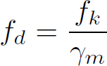
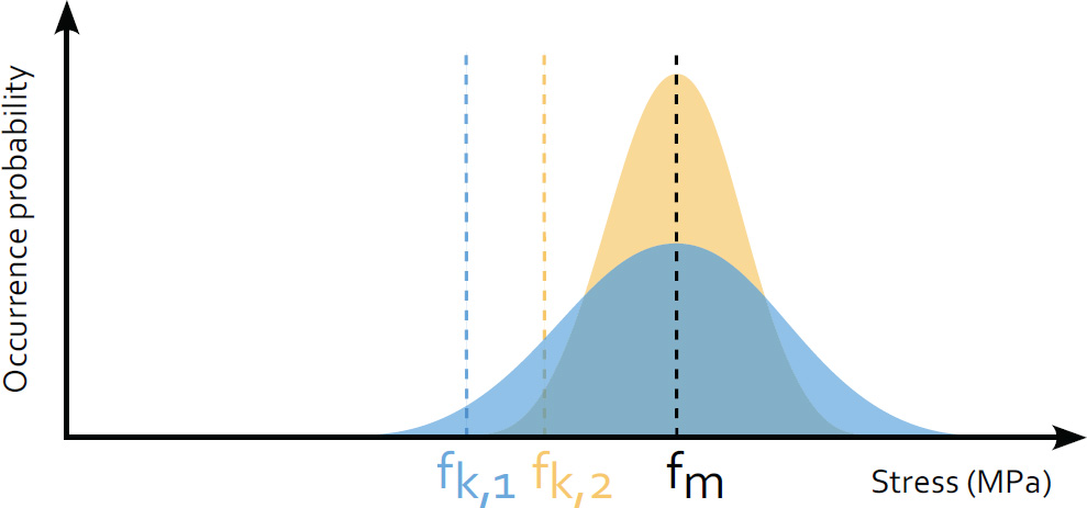
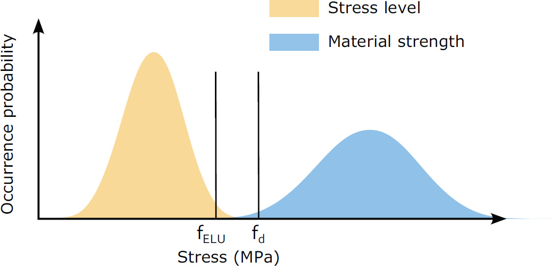
5.1.2. Principles of structural design
5.1.3. Chapter organization
5.2. Assessment of hardened material properties
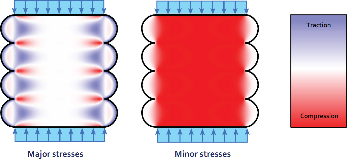
5.2.1. Material or micro-structure?
5.2.2. Toward reconciling points of view
5.2.3. Orthotropic or isotropic material?
 , which is symmetrical: the material parameters are the moduli Ei, the shear moduli Gij and the Poisson’s ratio νij. Similarly, adapting classical failure criteria such as the Drucker Prager model to the orthotropic case results in a similar increase in the number of parameters:
Category
Property
Symbol
To be evaluated specifically
Stiffness
Young’s modulus
Ei
Yes
Shear modulus
Gij
No
Poisson’s ratio
Vij
No
Robustness
Compressive strength
fck,1, fck,2
Yes
fck,3
No
Flexural strength
fbk,1, fbk,2
Yes
fbk,3
No
5.2.4. Mechanical testing
5.2.5. Conclusion
5.3. Masonry
5.3.1. Reinforced masonry
5.3.2. Confined masonry
Wall system
Thickness (cm)
Weight (kg/m2)
U-value (W.m–2.K–1)
Cinder blocks
40
180
0.1
Lightweight concrete
56
150
0.09
Precast wall
42
220
0.15
3D-printed truss
42
50
0.09
5.3.3. Shell structures
5.3.4. Link between process and structural behavior
5.3.5. Toward a stereotomic approach to printing
5.4. 3D printing and reinforced concrete
5.4.1. Lost or collaborative formwork?
5.4.2. Reinforced printed concrete
5.4.3. Fibering printed concrete
5.5. Prestressing
5.5.1. Principle
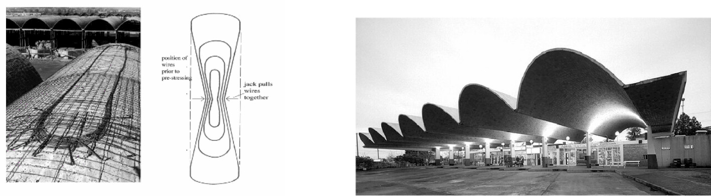
5.5.2. Application
5.5.3. Challenges
5.6. Conclusion
5.6.1. Structural optimization and additive manufacturing
5.6.2. The structural language of 3D printing
5.7. References
Notes
Structural Applications of 3D Printing
[5.1]
[5.2]