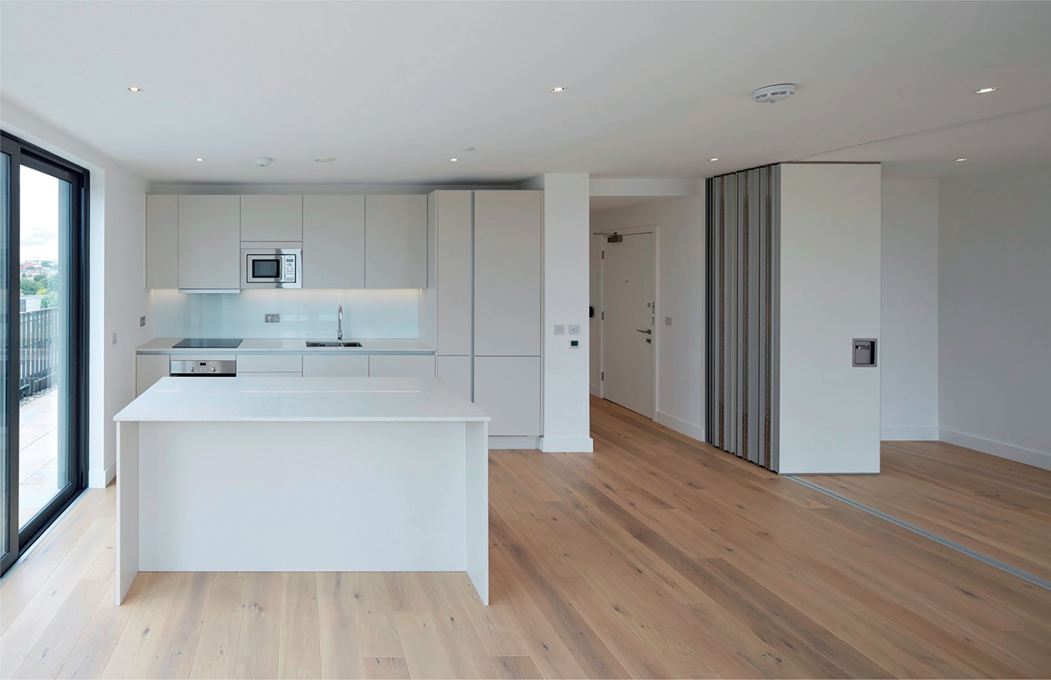
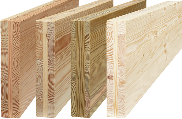
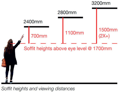
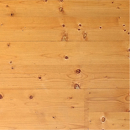
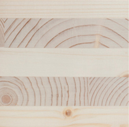
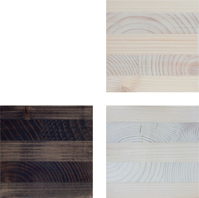
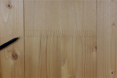
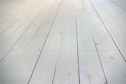
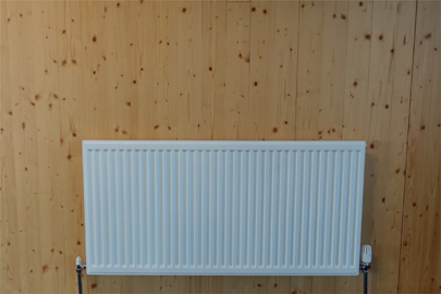
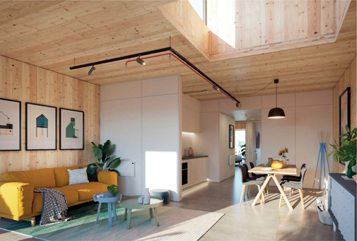
FIG 5.0 (chapter opener) The main prayer hall of Cambridge Mosque by Marks Barfield (2019), with white painted CLT wall and roof enclosure beyond tree form glulam structures. Exposing CLT reflects the increased expression of pattern, texture and natural materials in architecture and interiors and an apparent awareness and acceptance, or even celebration, of what the Japanese term wabi-sabi.1 However, CLT does not need to be visible to be advantageous in use. Limitations on expressing structural elements may be due to issues of perception, taste or important performance aspects, typically fire or acoustic issues. As such, typical CLT apartment buildings in the UK, including the highest profile examples, have nearly all (if not all) CLT panels concealed rather than exposed. As a composite formed from multiple sections of a natural material with inherent, sometimes significant variations, deviations in appearance must be expected. Some aspects can be controlled; others are less predictable or unavoidable. Other features may become apparent only over time, e.g. with changes to moisture content and resultant movement or exposure to light. Managing expectations from the outset is critical. Teams and clients should remember that all materials will move to some degree and even small cracks or tolerances may be noticeable when viewed across large panels and that structural elements (concrete, steel or timber) should not be assessed as one might a piece of furniture. Such detail is often overlooked leading to surprises on site and difficult conversations between teams and clients. Figure 5.1 shows AHMM’s Cobalt Place (102 apartments, completed 2015). CLT was reluctantly concealed to suit the sales agents’ idea of what would suit the local market (that included wooden flooring). Doing so did however prove a cost-effective and easily understood and conventional means of providing fire protection and appropriate acoustic performance. FIG 5.1 Typical interior view, full CLT structure concealed. It is important to understand and communicate the material’s character, behaviour and limitations and communicate these to stakeholders. Surface quality may be defined by local standards,1 but manufacturers each use differing terms to describe various finishes, as Table 5.1 shows.2 Manufacturers typically provide benchmark samples or indicative images but the importance of mock-ups cannot be stressed enough given the potential variety in appearance. In some markets, there may be a choice of species used to form CLT, or decorative outer layers, with differing performance and visual characteristics, as Figure 5.3. FIG 5.3 Timber species, availability and cost vary by region. Manufacturers typically offer a default (economic) option but may offer a range of timbers with differing characteristics and surface qualities. From left: Douglas Fir, Pine, UC3 pressure treated Pine, Spruce – as available from French manufacturer Piveteaubois. For a more detailed summary of the range of surface characteristics by grade, refer to ‘CLT Panel Surface Quality’ within the Appendix. The highest grade (often termed domestic visual quality) may be appropriate when exposed adjacent to occupied zones; however, other areas may suffice with more cost effective lower grade panel surfaces. Viewed from further away, a lower grade of panel may be sufficient visual quality and for overhead applications, only a modest increase in height, as Figure 5.4, can double the effective viewing distance. FIG 5.4 Soffit heights and effective viewing distances. Yellowing and aging, which may be referred to as ‘suntanning’, of spruce and other whitewoods (other timbers typically darken) is the visible sign of lignin degradation over time. This is caused by ultraviolet (UV) light from both natural and artificial sources although it will be most apparent in areas receiving direct sunlight.5 This effect, often seen within the interiors of older alpine chalets, has been described as ‘aging gracefully, mellowing to a rich honeyed tone over time’.6 Some may view it less favourably, particularly when it results in contrasting light and dark ‘shadows’ being created by areas protected from exposure by furniture, fittings or picture frames. Owners and occupiers should be made aware of the issue and although affected areas can be re-sanded to expose paler wood this can be disruptive to occupants. Some manufacturers offer factory-applied surface finishes such as clear or UV-protecting lacquers, UV stable silicate finishes, tinted or opaque finishes with or without fire retardant for limiting surface spread of flame but this is not typical. Most are reluctant to apply liquid coatings in their (dusty) factories to avoid slowing down production and taking up valuable space.7 Such finishes are typically applied on site once panels are installed, for similar reasons and although generally not conspicuous, clear finishes may change the light reflectivity of the surface slightly. Figure 5.6 illustrates a freshly sanded spruce panel edge. By way of contrast, Figure 5.7 indicates a section of wall of untreated spruce, exposed to internal artificial light for around three years. FIG 5.7 Aged spruce panel. FIG 5.6 Freshly sanded spruce sample. Decorative or protective waxes or oils may be applied to well-finished (domestic quality) panels to areas within reach of occupants (i.e. where most likely to show staining or dirt and oil build-up from occupant contact). Note that any stain or wax/oil treatment may highlight different parts of a panel depending upon whether the end grain is exposed or not (highlighting cut grain at panel edges). Figure 5.8A illustrates the effect of two coats of white wax/oil stain – the effect is marginal due to the pale colour of the stain and the timber but UV retardant additives ensure that this tone would be maintained. Figure 5.8B shows the effect of two coats of black wax/oil stain. The dramatic effect on the end grain (with radial rings seen) reflects the more absorbent nature of this section whereas the impact on the long grain sections is still limited.8 Lye is a surface treatment that mitigates the yellowing of softwoods (Figure 5.8C), enhancing the natural grain of wood and creating a light whitewashed effect when applied to spruce. FIG 5.8 Coatings on spruce, from top: Two coats of white wax oil; Two coats of black wax oil; Softwood lye treated. Surface boards may move or shrink and small gaps will likely open up – this is likely within the first year after installation and possibly beyond. Figure 5.9 illustrates gaps and cracking to vertical wall panels (as well as a visible finger joint to the outer board). Such cracks typically remain visible. FIG 5.9 Vertical splits to outer lamella of vertical wall panel (beside finger joint in surface board). Consider allowing a heating season before painting if possible. Figure 5.10 illustrates multiple fissures in the surface of a panel coated with two coats of white tinted fire-retardant finish shortly after the panels were installed. Despite each crack being only quite small, the colour contrast is quite marked. Such splits may be compounded above heat sources where the moisture content is reduced below that elsewhere in the building (Figure 5.11). Painting over knots, and surface deviations can be challenging; they will show through most light-coloured finishes being perceived as defects or marks. Consider a non-opaque colour tint to soften variations in the surface rather than trying to conceal them. FIG 5.10 Panel with two coats of opaque white finish, knots and splits clearly visible. FIG 5.11 Wall panel above radiator (with clear flame retardant finish) with disproportionate number of vertical splits due to localised heating and drying effects. NB: a vertical panel joint can be seen to the right of radiator. Many common areas and commercial or larger buildings will require a liquid applied fire-retardant coating to limit surface spread of flame to exposed panels. Such coatings may be transparent, tinted or opaque and coloured as required, with varying degrees of gloss or reflectance. All will however modify the matt finish of timber and may appear worn over time in highly trafficked areas where occupants come into regular contact with the surface. All finishes used should be compatible with treatments such as fire retardants or edge sealants. Panel connection design is frequently overlooked and can impact design time as well as cost. Exposed panels might be readily fixed with concealed fixings (fixings are typically long wood screws), screwed from back faces if access is readily available but will be more of a challenge when visible on both sides. Panel connections may be considered as follows: Although factory finish and panel quality can be high with extremely tight tolerances, very large and cumbersome panels can be easily mishandled and edges to be exposed are not readily repaired. Panels need to be manoeuvred on site and edges and corners can be easily damaged. Placing structural panels is not like crafting furniture so consider ‘aiming to miss’ – avoiding unrealistic details and outcomes by staggering joints, offsetting datum lines from prominent features or introducing chamfers, rebates or shadow gaps to panel edges to help ensure that installations are not compromised by matters beyond your control. Coordinating exposed panel corners such as at the intersection of four panels at a single point, for example, may be a challenge due to cumulative tolerances, however small. Surface board or grain direction should always be checked if it is being exposed to ensure it runs the intended direction and the visual quality of panel edges can be variable (they are typically not controlled), so it is important to discuss these with suppliers early. Panels are not intended to be exposed to moisture for significant periods. Figure 5.13 illustrates the effects of medium term exposure (nine months) on panel samples of spruce. Colour effects aside (samples exposed turned a glorious silver colour), samples exposed to water and air typically cracked and began to delaminate in part. The sample fully submerged displayed deformation but no decay (which would likely require exposure to air). FIG 5.13 Weathered samples, from left: Top surface fully exposed to weather; Fully submerged (no air). FIG 5.14 Example of a particularly convincing pre-construction render, of a proposed modular CLT scheme for developer Urban Splash. Many visualisations deliver an unrealistic impression of how exposed panels will look. Given the importance of managing stakeholder expectations and the increasing reliance on digital models and rendered outputs to inform decision making and sign-off from early stages (as well as potentially sales), Table 5.2 outlines what may be considered realistic when developing and presenting proposals. Such details may seem minor but will help avoid surprises, disappointment or extra work, ensuring proposals are acceptable, realistic and affordable.9 Consider reviewing outputs against images of any completed local precedents for comparison once these issues have been considered.
CHAPTER 5
VISUAL ASPECTS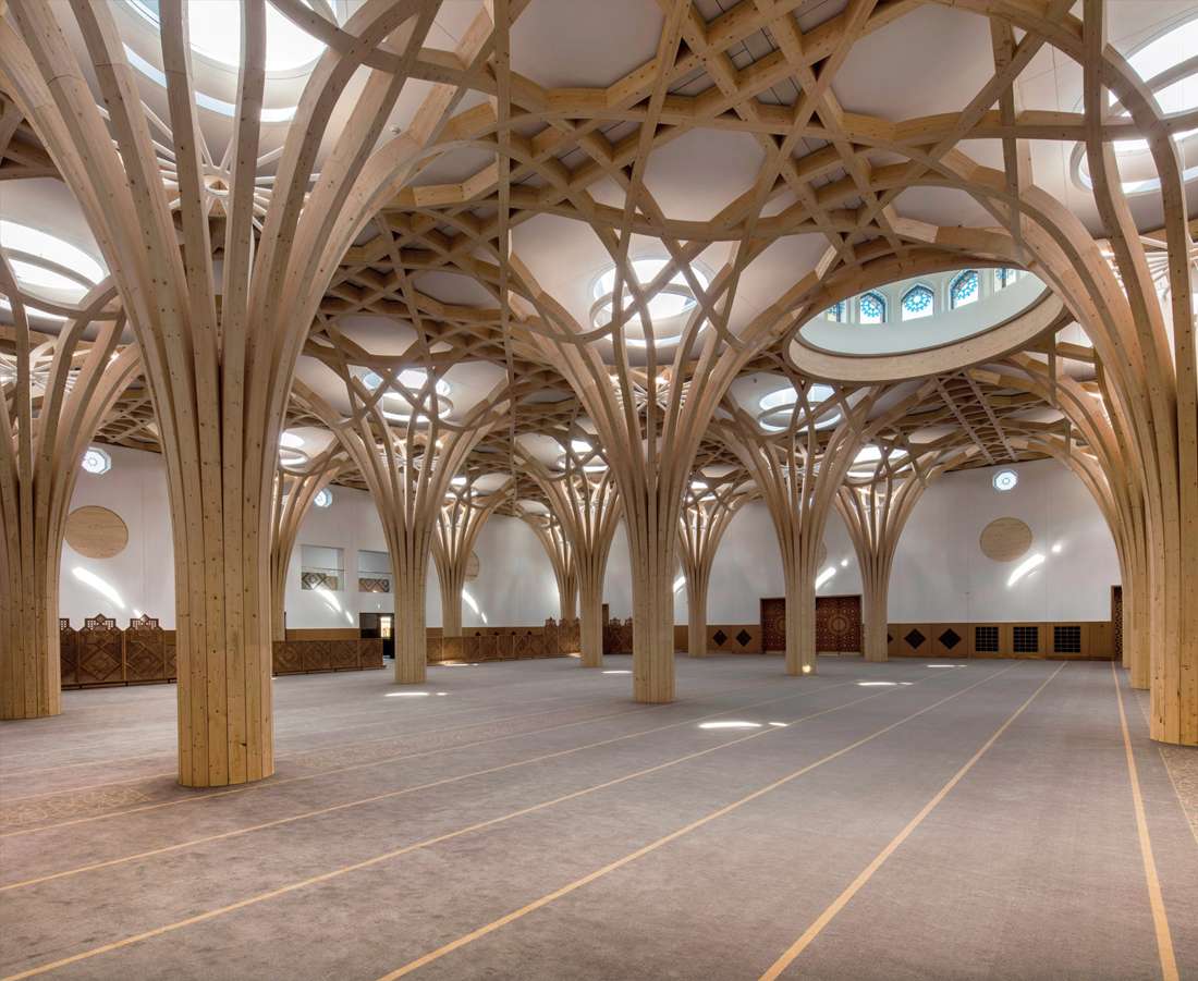
MANAGING EXPECTATIONS
DESIGN STAGE ISSUES
Surface appearance
Manufacturer
Lowest grade
Medium grade
Highest grade
According to European standard4
Visible surface not covered by standard
Planed, may be lightly sanded to Class B/C
Planed and sanded to Class A/B
Binderholz
Non-visible (NSI)
Industrial areas (class BC)
Living areas (AB)
KLH
Non-visual Quality (Nsi)
Industrial Visual Quality (Isi)
Domestic Visual Quality (Wsi)
Stora Enso
Non-visible guality (NVI)
Industrial Visible Quality (IVI)
Visible guality (VI)
Viewing panels in-situ
Aging of exposed timber
CLT surfaces and applied finishes
Panel connections and joint details
Appearance after exposure and wetting

Realistic rendering
Element
Aspect
Realistic representation
Not realistic
Soffit
Direction of boards on visible surface; Panel thickness where exposed
Boards aligned with primary direction of panel span i.e. to walls or between beams; panel thickness c.160-300mm depending on span
Misaligned with primary span; overly thick panels or lamella (see dimensions noted elsewhere)
Floor
Typically not used for flooring
Most softwoods are insufficiently durable for foot traffic. Show other flooring
Showing CLT panels exposed to form floors
Wall
Direction of visible boards (outer face); Panel thickness
Aligned vertically (typically), along lines of structural loading; panel thickness c.80-160mm depending on design
Horizontally aligned, i.e. perpendicular to loading; Very thick walls (>200mm)
Panels generally:
Panel size/joints
3m x 16m maximum (generally); narrow joints c.5mm; typically small chamfer to long edges (NB: outer layer direction typically defined by loading/span, as above, not panel orientation); Typically read as butt joint to visible surfaces
Seamless joints; panels not shown; Boards continuing across adjacent panels
Lamella board length (each lamella [layer] formed of board)
Long boards – typically mixed lengths up to 3m. Differentiation between boards at panel joints
Endless lamella boards; Lamella continuing past panel joints
Lamella board width
Typically consistent, c.130mm max width (high quality), c.200mm (regular grade)
Very wide boards; more than 300mm or varied width
Timber species/colour
Reflect local availability; Use paler colours as fresh sanded finish, not aged or ‘suntanned’
Unfamiliar or unrealistic timber species, grain or colour; Hardwoods (such as oak)
Knots; Growth rings; Defects and surface variation
Typically includes knots, often very many, up to 40mm dia. See description of panel grade elsewhere. Growth rings will be varied and visible unless viewed from afar; Scale and contrast within boards will vary
No, or few, knots shown. Even panels with little or no colour or surface variation, no visible growth lines
Exposed edges
Odd number of lamella (typically 3/5 for walls, 5/7 for slabs). Alternating parallel/perpendicular make-up for adjacent layers
Even number of lamella; unrealistic thickness; perfect appearance of cross layers (NB: controlling quality of layers exposed at board edges is not typical)
Panel connections
Can be concealed/’not visible’ if specified (may attract a premium to exposed panel joints or to glulam elements)
No fixings shown, particularly with hybrid forms e.g. glulam beam/wall interfaces
Other details
Services
Can be concealed (i.e. fed from rear or drilled into panel) if considered early, otherwise must be surface mounted (including distribution runs). Compartment penetrations may require fire stopping
Visible service penetrations with no tolerance/fire stopping